EP0236728A2 - Improved transit for cables and pipes - Google Patents
Improved transit for cables and pipes Download PDFInfo
- Publication number
- EP0236728A2 EP0236728A2 EP87101465A EP87101465A EP0236728A2 EP 0236728 A2 EP0236728 A2 EP 0236728A2 EP 87101465 A EP87101465 A EP 87101465A EP 87101465 A EP87101465 A EP 87101465A EP 0236728 A2 EP0236728 A2 EP 0236728A2
- Authority
- EP
- European Patent Office
- Prior art keywords
- blocks
- lead
- block
- recesses
- cable
- Prior art date
- Legal status (The legal status is an assumption and is not a legal conclusion. Google has not performed a legal analysis and makes no representation as to the accuracy of the status listed.)
- Granted
Links
- 230000006835 compression Effects 0.000 claims abstract description 35
- 238000007906 compression Methods 0.000 claims abstract description 35
- 230000000295 complement effect Effects 0.000 claims abstract description 11
- 239000012858 resilient material Substances 0.000 claims description 4
- 239000002184 metal Substances 0.000 claims description 3
- 238000009434 installation Methods 0.000 abstract description 7
- 238000007789 sealing Methods 0.000 abstract description 5
- 239000000463 material Substances 0.000 description 6
- 238000012856 packing Methods 0.000 description 6
- 239000007787 solid Substances 0.000 description 4
- 230000004323 axial length Effects 0.000 description 3
- 238000005192 partition Methods 0.000 description 3
- 230000007547 defect Effects 0.000 description 2
- 238000006073 displacement reaction Methods 0.000 description 2
- 230000000694 effects Effects 0.000 description 2
- 238000003780 insertion Methods 0.000 description 2
- 230000037431 insertion Effects 0.000 description 2
- XLYOFNOQVPJJNP-UHFFFAOYSA-N water Substances O XLYOFNOQVPJJNP-UHFFFAOYSA-N 0.000 description 2
- 241000283984 Rodentia Species 0.000 description 1
- 230000032683 aging Effects 0.000 description 1
- 230000033228 biological regulation Effects 0.000 description 1
- 238000010276 construction Methods 0.000 description 1
- 238000011109 contamination Methods 0.000 description 1
- 230000005611 electricity Effects 0.000 description 1
- 230000007613 environmental effect Effects 0.000 description 1
- 239000003344 environmental pollutant Substances 0.000 description 1
- 230000009970 fire resistant effect Effects 0.000 description 1
- 231100001261 hazardous Toxicity 0.000 description 1
- 238000011065 in-situ storage Methods 0.000 description 1
- 230000014759 maintenance of location Effects 0.000 description 1
- 238000004519 manufacturing process Methods 0.000 description 1
- 238000005259 measurement Methods 0.000 description 1
- 231100000719 pollutant Toxicity 0.000 description 1
- 239000011800 void material Substances 0.000 description 1
Images


Classifications
-
- F—MECHANICAL ENGINEERING; LIGHTING; HEATING; WEAPONS; BLASTING
- F16—ENGINEERING ELEMENTS AND UNITS; GENERAL MEASURES FOR PRODUCING AND MAINTAINING EFFECTIVE FUNCTIONING OF MACHINES OR INSTALLATIONS; THERMAL INSULATION IN GENERAL
- F16L—PIPES; JOINTS OR FITTINGS FOR PIPES; SUPPORTS FOR PIPES, CABLES OR PROTECTIVE TUBING; MEANS FOR THERMAL INSULATION IN GENERAL
- F16L5/00—Devices for use where pipes, cables or protective tubing pass through walls or partitions
- F16L5/02—Sealing
- F16L5/08—Sealing by means of axial screws compressing a ring or sleeve
-
- F—MECHANICAL ENGINEERING; LIGHTING; HEATING; WEAPONS; BLASTING
- F16—ENGINEERING ELEMENTS AND UNITS; GENERAL MEASURES FOR PRODUCING AND MAINTAINING EFFECTIVE FUNCTIONING OF MACHINES OR INSTALLATIONS; THERMAL INSULATION IN GENERAL
- F16L—PIPES; JOINTS OR FITTINGS FOR PIPES; SUPPORTS FOR PIPES, CABLES OR PROTECTIVE TUBING; MEANS FOR THERMAL INSULATION IN GENERAL
- F16L5/00—Devices for use where pipes, cables or protective tubing pass through walls or partitions
- F16L5/02—Sealing
- F16L5/14—Sealing for double-walled or multi-channel pipes
-
- H—ELECTRICITY
- H02—GENERATION; CONVERSION OR DISTRIBUTION OF ELECTRIC POWER
- H02G—INSTALLATION OF ELECTRIC CABLES OR LINES, OR OF COMBINED OPTICAL AND ELECTRIC CABLES OR LINES
- H02G3/00—Installations of electric cables or lines or protective tubing therefor in or on buildings, equivalent structures or vehicles
- H02G3/22—Installations of cables or lines through walls, floors or ceilings, e.g. into buildings
Definitions
- This invention relates to a transit providing a lead-through for electric cables or pipes that are required to extend through an opening in a wall, bulkhead, partition or the like.
- This invention concerns certain improvements in a particular kind of transit as hereinafter defined and which is for use with cables, wires, pipes or tubes or the like elongate elements commonly used in an installation for conducting electricity, service commodities such as gas, oil or water, or enclosing such service lines.
- service commodities such as gas, oil or water, or enclosing such service lines.
- the term "cable" is used and should be interpreted in the context to include all such aforesaid elongate elements.
- This invention is particularly concerned with a transit of the kind now defined as comprising a rectangular metal frame defining an opening through which the cables are to extend, a series of sets of modular blocks for assembly in rows within the frame opening, the blocks being adapted for surrounding each cable or for blanking off a modular space, and a compression and packer assembly for mounting in the frame opening to clamp the assembled blocks together and around each cable with the compression and packer assembly completing filling of the frame opening.
- transits of the defined kind are used in a wide range of applications and are installed in various environments including hazardous and have to meet specific regulations for fire-proof or flame-proof or gas-tight installations.
- a transit has to be assembled on site and often the working conditions at the installation site are difficult in many respects, such as:- access and location; the numbers, types and sizes of cable; limited working space and lack of access to both inlet and exit sides of the lead-through; and, ambient temperature, weather and environmental conditions.
- each block in each series set of the modular blocks, is of square section and has a length substantially the same as the depth of the metal frame into which the blocks are assembled in an array of superimposed rows.
- Each block in a set of blocks has the same external dimensions and a plurality of blocks from one set will completely fill one row across the inside of the frame.
- each set includes solid blank blocks for assembly in the row.
- the blocks have a through hole of a diameter corresponding to the diameter of the cable to be surrounded by the block, and to facilitate fitting and assembly each such block is formed in two complementary halves with semi-cylindrical recesses that, when aligned, provide the lead-through hole in which the cable is seated.
- each set having a different modular size.
- This arrangement leads to many complications because of the numbers of blocks to be made and available on site for assembly when the cable transit is installed.
- the size of the cable for which lead-through blocks are specified and provided is found on site to be outside the given nominal diameter and cannot be properly seated into the half-blocks.
- cables are often not uniform in diameter along their length due to local deformation or manufacturing tolerances or defects.
- the known cable transits of the defined kind have a sized lead-through blocks corresponding to each nominal cable size, and as a result extreme care is required to select the sized lead-through block equal to the diameter of the cable, and complications arise if the cables are not perfectly round and on-site measurements may be essential to obtain accurate fitting and sealing.
- the lead-through blocks are for resilient conformation to a selected cable of a size within specific limits
- the lead-through block comprising two complementary similar halves for assembly together to define the lead-through
- the lead-through block having a through passage defined by a plurality of axially spaced cylindrical lands for engagement with the selected cable, a plurality of recesses extending intermediate each land being adapted to enable the lead-through block to conform resiliently within the specific limits to the selected cable to clamp and seal the lands to the cable when the cable transit is assembled.
- the same lead-through block can be employed for a range of cable sizes that are within the range of specific limits for resilient conformation of the lead-through block.
- the total numbers of lead-through blocks can be reduced compared with the conventional systems of accurately sized blocks for each cable size.
- the recesses intermediate each land may be of annular form.
- the radial depth of each recess may be chosen with respect to the overall size of the block to ensure that the land portion is deformable uniformly around the periphery into the annular recesses.
- recesses may be formed in the outer walls of the lead-through block to locally reduce the wall thickness so that the block may be resiliently deformable.
- outer recesses may in formed as channel or U-shaped grooves extending in the side walls of each lead-through block and extending transversely to the axis of the lead-through.
- the outer recesses may extend on two opposed side walls of the lead-through block or may extend around all four sides.
- the blank blocks should also have the same type of outer recess formed therein so as to have an outer configuration the same as the lead-through blocks.
- the improved cable transit comprises a rectangular frame 1 defining an opening 2 through which cables 3 of different sizes extend.
- Each cable 3 is held within a lead-through block 4 whilst blank blocks 5 fill the modular spaces of the opening where no cable is present.
- the frame is for mounting or support in an aperture in a bulkhead or partition or the like (not shown) and the numbers and sizes of cables may vary from one installation to another.
- the assembly is not as complex as found in practice where tens of cables may have to be accommodated and installed at the site location.
- each series set has a common length corresponding substantially to the depth of the opening 2 and the frame 1.
- Each series set has blocks of substantially square section with the respective width and height dimensions of each set being selected to a common multiple so that a plurality of blocks of each set will complete a row or fill a modular space within the frame.
- Typical suitable modular dimensions are 90mm, 60mm and 30mm for the square section blocks.
- Each set of blocks is assembled in a row and to separate and support the assembled rows, stay plates 6 extend therebetween to locate on the marginal edges of the side walls of the frame 1.
- the opening 2 is closed by a compression and packer assembly 7 which clamps and holds the rows of blocks in place and applies pressure to the blocks.
- the compression and packer assembly 7 comprises a pressure plate 8, three compression blocks 9,10 and 11 each having a respective compressor stud 12,13 and 14 extending therethrough.
- Each compression block 9,10 and 11 has a respective rear support plate 15,16 and 17 against which the rear head of each respective stud 12,13 and 14 engages.
- Each stud 12,13 and 14 extends through the respective block and through aligned openings in a front support plate 18 with respective nuts 19,20 and 21 being in threaded engagement with the free end of the associated stud projecting through the front support plate 18.
- the pressure plate 8 is a rigid body having a planar underside 22 for engagement with the upper faces of the top row of blocks 4 a and 5 a , and an edge flange 23 on each side of the plate 8 provides location ledges over-lying the upper marginal edges of the blocks as well as providing outer end lug portions that extend outwardly and engage the outer faces of the sides of the frame 1.
- the topside of the plate 8 has a flat central portion 24 and opposed inclined portions 25.
- Each of the compression blocks 9,10 and 11 are made of a resilient material and the outer blocks 9 and 11 have respective through holes 26,27 that extend transverse and spaced from the respective axes of the compression studs 12 and 14.
- a respective limit pin 28 is mounted in each through hole 26,27 and this pin 28 is arranged to engage the inner face of the top of the frame 1 and the inclined portion of the pressure plate 8 so as to limit the degree of deformation of the blocks 9 and 11 when compression loading is applied to the blocks in the direction of the axis of the limit pins as later explained.
- the upper wall 29 of the frame 1 is provided with a central clearance hole 30.
- a hexagonal shaped boss 31 is rigidly mounted on the upper wall 29 and projects therefrom aligned with the clearance hole 30.
- the boss has an internal blind threaded bore 32 and a compression bolt 33 is in threaded engagement within the bore 32 with the head 34 of the bolt 33 being accessible through the clearance hole 30 for rotation by a suitable tool.
- the bolt 34 can be unthreaded to extend into the void below the boss 31 when the central compression block 10 is not fitted, and the head 34 of the bolt will engage with the central portion 24 of the plate 8.
- the compression blocks 9 and 11 are similar and have inner taper faces that lie adjacent to the opposed side faces of the central compression block 10.
- the central block 10 is generally in the form of a wedge with the opposed side faces diverging from the front of the block as well as converging towards each other towards the underside of the block to present a flat underside face 35 engaging the flat central portion 24 of the plate 8.
- the inner taper faces of the outer compression blocks 9 and 10 are complementary to the wedge faces of the central block 10.
- the underside faces of the compression blocks 9 and 10 are inclined and complementary to the respective inclined portions 25 of the plate 8.
- each lead-through block 4 is similar and comprises two complementary half-blocks 40 that are assembled together with the cable extending therebetween as shown in Figure 1 and as is generally known in cable transits of the kind defined.
- All of the modular blocks are formed from a resilient material which may be the same material as used for the compression blocks 9,10 and 11.
- Each half-block 40 provides a semi-cylindrical passageway 41 and the internal surface of the half-block is divided into semi-annular lands 42 which are separated by semi-annular recesses 43 which are concentric to the lands 42.
- the recesses 43 are spaced along the axial length of the half-block and preferably, as shown, each end of the passageway 41 is defined by a land 42 and not a recess 43. In short, if the number of the lands is "n”, then the number of recesses is "n-1".
- each land 42 is arranged for engagement with the outer surface of a cable 3, and due to the resilient nature of the block material, on clamping of the half-blocks to and around the cable, each land 42 seals to the cable surface and irregularities of size or shape of the cable can be accommodated by local deformation of each land portion with the block material being squeezed or otherwise displaced into the separate voids provided by the recesses 43.
- the half-blocks can resiliently deform to conform to the cable.
- each half-block 40 is provided in it's outer opposed side walls with channel-shaped recesses 44 that are spaced apart and lie in register opposed to each of the internal lands 42.
- the width of each recess in the axial direction is less than the corresponding axial width of the opposed land, and each of the outer recesses 44 assists in achieving the degree of resilient conformation of the lead-through block. It is preferred that the outer recesses 44 do not extend to the outer ends of each half-block, and this may be expressed shortly as "n-2" outer recesses where "n" is the number of lands.
- each lead-through block 4 has two complementary half-blocks 140 defining a semi-cylindrical passageway 141.
- the internal surface of the half-block is divided into semi-annular lands 142 which are separated by semi-annular recesses 143 which are concentric to the lands 142.
- the recesses 143 are spaced regularly along the axial length of the half-block and each end of the passageway 141 is defined by a land 142.
- the lands 142 are for engagement with the outer surface of the cable as aforedescribed.
- each half-block is relieved by semi-annular recesses 144 which are concentric to the lands 142 and which are in diametric alignment therewith.
- the width (in the axial direction) of each recess 144 is preferably less than the width of the aligned land 142.
- the outer end of each half-block is not relieved by any such outer recess, and if the number of lands 142 is "n", then the number of inner recesses 143 is "n-1" and the number of outer recesses 144 is "n-2".
- each outer recess with respect to the outer side and bottom faces of the block will not be constant whereas the central portion of each land 143 will be backed up by a portion of block material of uniform thickness having regard to the concentric arrangement.
- the relieved portions of the lead-through block both beside and behind each land will aid flexibility and conformation of the lead-through block when engaged with a cable.
- the solid blank blocks 5 solid shall have the same form of outer recesses as the lead-through blocks so that the outward configuration of each block is the same in the modular series set.
- the solid blank blocks 5 may have planar outer surfaces as they are not required to have such resilient conformation to suit a cable extending therethrough.
- the upper and lower faces of the block may also be formed with channel-shaped recesses contiguous with the recesses 44 formed in the opposed side walls.
- the recesses formed in the outer faces of the blocks must not provide a leak or flame path from one side of the assembled transit to the other, and the outer faces of the blocks must provide sealing engagement with each other and the inner face of the frame as well as with the stay plates 6 and the pressure plate 8.
- the arrangement of recesses in the outer faces of the blocks are preferably complementary to provide sealing engagement at the respective interfaces.
- the numbers of lands provided would normally be more than two and not more than ten, and the numbers of inner recesses and outer recesses would be varied in accordance with the "n" formula as given earlier.
- each passageway provided through the lead-through blocks will be selected for a nominal cable size, and a range of larger sizes to which the lead-through block can conform by the resilient deformation achieved on assembly and fitting as will now be described.
- the cable transit as aforedescribed is assembled from the individual components, and firstly the frame 1 is located in the structure with the runs of cables 3 extending through the opening 2 of the frame 1.
- the fitter is presumed to have the selection of modular blocks 4 for each cable and a number of blanking blocks 5.
- the largest lead-through blocks 4 c are used in the lower row, and firstly the lower half-blocks 40 c are set against the bottom inner wall of the frame 1 and each respective cable 3 is seated in the semi-cylindrical passageway and then the upper half-block 40 c is seated on top to form the lead-through block closing over the cable and forming the lower row.
- the stay plate 6 is then inserted in place on top of the row of blocks with the marginal flanged edges of the stay plate 6 riding over the side edges of the frame 1 to locate the stay plate 6 in a similar manner as for the pressure plate 8.
- the stay plate has a central web portion which is pierced or of mesh to prevent high rates of heat transfer from one side to the other of the cable transit when installed.
- the fitter selects the next cables 3 to be located in the lead-through blocks 4 b for the next row and this row includes a blanking block 5.
- this row includes a blanking block 5.
- another stay plate 6 is located over the row of blocks.
- the third row of blocks 4 a and 5 a is then assembled in a similar manner, and all of the cable runs are enclosed by the selected lead-through blocks with the lower portion of the frame opening being filled by the rows of blocks and the stay plates 6.
- the pressure plate 8 is located over the third row of blocks and seated over the assembled array of blocks and cables. Due to the resilient nature of the blocks and the effect of the cables, pressure must be applied to the assembled blocks to compress the blocks around the cables to seal the lead-through blocks both around the cable and to clamp them together and against the side walls of the frame 1.
- the compression bolt 33 is rotated to bring the head 34 into engagement with the flat central portion 24 of the plate 8 and on further rotation of the head 34 compressive forces are applied through the plate 8 to the assembled blocks.
- the fitter can insert the two outer compression blocks 9 and 11 in the clearance space clear of the compression bolt which only extends to the centre of the clearance space and does not interfere with the fitting of the two side blocks 9 and 11.
- the compression bolt 33 can be counter-rotated to return the bolt into the bore of the boss 31 leaving the central area over the pressure plate 8 free for insertion of the central wedge shaped compression block 10 between the two side blocks 9 and 11.
- the assembly of the rows of blocks and cables will continue to exert reactive forces on the pressure plate 8 tending to displace it towards the top wall of the frame, and thus tending to compress the blocks 9 and 11.
- the limit pins 28 mounted in the compression blocks 9 and 11 restrict squeezing of the blocks.
- each of the compression blocks 9,10 and 11 can be engaged over the free ends of each of the compressor studs 12,13 and 14 and the respective nuts 19,20 and 21 placed in threaded engagement.
- the fitter then tightens each of the nuts 19,20 and 21 to apply compressive forces to the compression blocks so that the three blocks are brought into wedge clamping engagement with each other and brought into engagement with the support plate 18.
- each of the compression blocks 9,10 and 11 is squeezed so as to cause resilient displacement of the block material in a direction transverse to the axis of each compressor stud thereby expanding the assembly both to fill the clearance opening between the pressure plate 8 and the frame 1 and to exert the required clamping pressure onto the assembly of blocks and cables beneath the pressure plate 8.
- the compression and packer assembly 7 completes the filling of the opening 2 in the frame 1 whilst also applying the necessary forces to the assembled rows of blocks and cables to ensure that whole assembly is sealed together and securely located against displacement.
- each lead-through block is designed for use with more than one cable size and to be tolerant of local irregularities and non-uniform sections of cables.
- the fitting of the cable transit arises in various environments, and the cable transit may be installed as described in the vertical position, but it may be installed horizontally where safe retention and ease of assembly of the blocks and other component parts is required.
- the fitter may have to work in elevated positions on ladders or in confined positions where the number of blocks with existing transits is excessive with one block for each size of cable.
- the exemplary embodiments described are simplified for an understanding of this invention, and the numbers and relative dimensions of the lands and inner and outer recesses may be varied to achieve the degree of conformability required.
- the inner and outer recesses may be of any suitable sectional shape or configuration.
- the resilient material of which the lead-through and blanking blocks as well as the compression blocks are made can be of any suitable material which is flame-resistant, fire-resistant, water-resistant and resistant to effects of rodent attack, ageing, and temperature variations.
- cables as this is the commonest form of use of transits through bulkheads, partitions or the like.
- the invented cable transit can be used and applied to pipes or conduits and the term “cable” is not intended to be a limitation to the application and use of the invention nor is the use of the term “cable” to be interpreted as a limitation to the scope of this invention.
Landscapes
- Engineering & Computer Science (AREA)
- General Engineering & Computer Science (AREA)
- Mechanical Engineering (AREA)
- Architecture (AREA)
- Civil Engineering (AREA)
- Structural Engineering (AREA)
- Laying Of Electric Cables Or Lines Outside (AREA)
- Installation Of Indoor Wiring (AREA)
- Supports For Pipes And Cables (AREA)
Abstract
Description
- This invention relates to a transit providing a lead-through for electric cables or pipes that are required to extend through an opening in a wall, bulkhead, partition or the like. This invention concerns certain improvements in a particular kind of transit as hereinafter defined and which is for use with cables, wires, pipes or tubes or the like elongate elements commonly used in an installation for conducting electricity, service commodities such as gas, oil or water, or enclosing such service lines. For convenience herein, the term "cable" is used and should be interpreted in the context to include all such aforesaid elongate elements.
- This invention is particularly concerned with a transit of the kind now defined as comprising a rectangular metal frame defining an opening through which the cables are to extend, a series of sets of modular blocks for assembly in rows within the frame opening, the blocks being adapted for surrounding each cable or for blanking off a modular space, and a compression and packer assembly for mounting in the frame opening to clamp the assembled blocks together and around each cable with the compression and packer assembly completing filling of the frame opening.
- Such defined kind of transit for cables is well known and is disclosed in Patent Specification GB 1,049,621.
- Typically, transits of the defined kind are used in a wide range of applications and are installed in various environments including hazardous and have to meet specific regulations for fire-proof or flame-proof or gas-tight installations. Usually, a transit has to be assembled on site and often the working conditions at the installation site are difficult in many respects, such as:- access and location; the numbers, types and sizes of cable; limited working space and lack of access to both inlet and exit sides of the lead-through; and, ambient temperature, weather and environmental conditions.
- Conventionally in transits of the defined kind, in each series set of the modular blocks, each block is of square section and has a length substantially the same as the depth of the metal frame into which the blocks are assembled in an array of superimposed rows. Each block in a set of blocks has the same external dimensions and a plurality of blocks from one set will completely fill one row across the inside of the frame. To provide blanks at locations in a row where no lead-through is required, each set includes solid blank blocks for assembly in the row. For a cable lead-through, the blocks have a through hole of a diameter corresponding to the diameter of the cable to be surrounded by the block, and to facilitate fitting and assembly each such block is formed in two complementary halves with semi-cylindrical recesses that, when aligned, provide the lead-through hole in which the cable is seated.
- As will be appreciated, in known transits for cables the series sets of blocks are several, each set having a different modular size. In each set, as well as the blank blocks, there have to be blocks that have through holes of many different diameters for a comprehensive wide range of cable sizes. For example, there may be eight modular sizes and hole diameters of from 4mm to 100mm are required sized to 1mm intervals. This arrangement leads to many complications because of the numbers of blocks to be made and available on site for assembly when the cable transit is installed. In addition, sometimes the size of the cable for which lead-through blocks are specified and provided is found on site to be outside the given nominal diameter and cannot be properly seated into the half-blocks. Furthermore, cables are often not uniform in diameter along their length due to local deformation or manufacturing tolerances or defects.
- In practice, the known cable transits of the defined kind have a sized lead-through blocks corresponding to each nominal cable size, and as a result extreme care is required to select the sized lead-through block equal to the diameter of the cable, and complications arise if the cables are not perfectly round and on-site measurements may be essential to obtain accurate fitting and sealing.
- In attempts to overcome some practical problems, it has been necessary to provide packing strips which are of a specified thickness and which the fitter has to fix around the cable either to increase it's overall diameter to suit the lead-through block, or in some instances, to cover a local irregularity or defect. In some existing transit systems, the lead-through blocks are not made with holes sized to 1mm intervals, and the use of such packing strips is an issential and integral part of the system. Many problems arise with such packing strips, particularly in view of the installation conditions and the manual dexterity required as well as the risk of contamination of the lead-through by dirt or pollutants when fixing the packing strip on site.
- Thus, with existing systems, a very large number of lead-through blocks have to be made and handled and available on site to ensure that all possible permutations of cables can be accommodated through the cable transit and special intermediate steps using separate pieces of packing strip may be required on site.
- Accordingly, it is a primary aim of this invention to provide a transit of the defined kind which is easy and simple to install with the number of component parts to be assembled at the installation site being less than in prior transit systems such as aforementioned.
- It is an object of this invention to provide an improved transit of the defined kind and wherein the number of lead-through blocks required to accommodate a wide range of cable sizes are less than previously.
- It is a further object of this invention to provide a cable transit of improved construction which can be used either with cables which are not of uniform diameter or which have a small variations in diameter along their axial length.
- Other objectives and advantageous features of this invention will be referred to later herein.
- According to this invention, we provide a transit of the defined kind for cables or the like characterised in that the lead-through blocks are for resilient conformation to a selected cable of a size within specific limits, the lead-through block comprising two complementary similar halves for assembly together to define the lead-through, the lead-through block having a through passage defined by a plurality of axially spaced cylindrical lands for engagement with the selected cable, a plurality of recesses extending intermediate each land being adapted to enable the lead-through block to conform resiliently within the specific limits to the selected cable to clamp and seal the lands to the cable when the cable transit is assembled.
- By this invention, instead of providing one size of lead-through block for each size of cable, the same lead-through block can be employed for a range of cable sizes that are within the range of specific limits for resilient conformation of the lead-through block. Thus, the total numbers of lead-through blocks can be reduced compared with the conventional systems of accurately sized blocks for each cable size.
- In addition, by this invention, it is possible to accommodate the common irregularities in the nominal diameter of the cable, in particular when nominal sized cables are found to be over-size or slightly oval. The use of separate packing strips is obviated.
- Conveniently, the recesses intermediate each land may be of annular form. By this arrangement, the radial depth of each recess may be chosen with respect to the overall size of the block to ensure that the land portion is deformable uniformly around the periphery into the annular recesses.
- According to another preferred feature of this invention, to further aid the conformability of the lead-through blocks, recesses may be formed in the outer walls of the lead-through block to locally reduce the wall thickness so that the block may be resiliently deformable.
- These outer recesses may in formed as channel or U-shaped grooves extending in the side walls of each lead-through block and extending transversely to the axis of the lead-through.
- The outer recesses may extend on two opposed side walls of the lead-through block or may extend around all four sides.
- If outer recesses are formed in the lead-through blocks, it is preferred that the blank blocks should also have the same type of outer recess formed therein so as to have an outer configuration the same as the lead-through blocks.
- Other features of this invention will now be described with reference to exemplary embodiments depicted in the accompanying drawings wherein:-
- FIGURE 1 is a front elevation of a cable transit according to this invention shown in the assembled position with cables in situ;
- FIGURE 2 is a partly sectioned side view of the cable transit shown in Figure 1;
- FIGURE 3 is an isometric view of part of the compression and packer assembly;
- FIGURE 4 is a detail sectional view of part of assembly shown in Figure 3 and as indicated therein;
- FIGURE 5 is an isometric view of the compression plate of the compression and packer assembly;
- FIGURE 6 is a detail isometric view of a lead-through block showing the two complementary half-blocks;
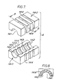
- FIGURE 7 is a detail isometric view of an alternative form of lead-through block showing the two complementary half-blocks; and
- FIGURE 8 is a detail section on line 8-8 as shown in Figure 7.
- With reference to the drawings of Figures 1 and 2, the improved cable transit comprises a rectangular frame 1 defining an opening 2 through which
cables 3 of different sizes extend. Eachcable 3 is held within a lead-throughblock 4 whilstblank blocks 5 fill the modular spaces of the opening where no cable is present. In known manner, the frame is for mounting or support in an aperture in a bulkhead or partition or the like (not shown) and the numbers and sizes of cables may vary from one installation to another. For simplicity of explanation of this invention, only a small number of cables are depicted and the assembly is not as complex as found in practice where tens of cables may have to be accommodated and installed at the site location. - In this embodiment, there is depicted three series of modular sized sets of lead-through and blank blocks of which the sizes are designated by the suffixes a, b and c. Each series set has a common length corresponding substantially to the depth of the opening 2 and the frame 1. Each series set has blocks of substantially square section with the respective width and height dimensions of each set being selected to a common multiple so that a plurality of blocks of each set will complete a row or fill a modular space within the frame. Typical suitable modular dimensions are 90mm, 60mm and 30mm for the square section blocks.
- Each set of blocks is assembled in a row and to separate and support the assembled rows, stay plates 6 extend therebetween to locate on the marginal edges of the side walls of the frame 1.
- In addition, the opening 2 is closed by a compression and
packer assembly 7 which clamps and holds the rows of blocks in place and applies pressure to the blocks. - With reference also to Figures 3,4 and 5, the compression and
packer assembly 7 comprises apressure plate 8, threecompression blocks respective compressor stud compression block rear support plate respective stud stud front support plate 18 withrespective nuts front support plate 18. - The
pressure plate 8 is a rigid body having aplanar underside 22 for engagement with the upper faces of the top row ofblocks 4a and 5a, and anedge flange 23 on each side of theplate 8 provides location ledges over-lying the upper marginal edges of the blocks as well as providing outer end lug portions that extend outwardly and engage the outer faces of the sides of the frame 1. The topside of theplate 8 has a flat central portion 24 and opposedinclined portions 25. - Each of the
compression blocks outer blocks 9 and 11 have respective throughholes compression studs respective limit pin 28 is mounted in each throughhole pin 28 is arranged to engage the inner face of the top of the frame 1 and the inclined portion of thepressure plate 8 so as to limit the degree of deformation of theblocks 9 and 11 when compression loading is applied to the blocks in the direction of the axis of the limit pins as later explained. - The
upper wall 29 of the frame 1 is provided with acentral clearance hole 30. A hexagonalshaped boss 31 is rigidly mounted on theupper wall 29 and projects therefrom aligned with theclearance hole 30. The boss has an internal blind threaded bore 32 and acompression bolt 33 is in threaded engagement within thebore 32 with thehead 34 of thebolt 33 being accessible through theclearance hole 30 for rotation by a suitable tool. As should be appreciated, thebolt 34 can be unthreaded to extend into the void below theboss 31 when thecentral compression block 10 is not fitted, and thehead 34 of the bolt will engage with the central portion 24 of theplate 8. - The compression blocks 9 and 11 are similar and have inner taper faces that lie adjacent to the opposed side faces of the
central compression block 10. Thecentral block 10 is generally in the form of a wedge with the opposed side faces diverging from the front of the block as well as converging towards each other towards the underside of the block to present aflat underside face 35 engaging the flat central portion 24 of theplate 8. The inner taper faces of the outer compression blocks 9 and 10 are complementary to the wedge faces of thecentral block 10. The underside faces of the compression blocks 9 and 10 are inclined and complementary to the respectiveinclined portions 25 of theplate 8. - With reference also to Figure 6, each lead-through
block 4 is similar and comprises two complementary half-blocks 40 that are assembled together with the cable extending therebetween as shown in Figure 1 and as is generally known in cable transits of the kind defined. - All of the modular blocks are formed from a resilient material which may be the same material as used for the compression blocks 9,10 and 11.
- Each half-
block 40 provides asemi-cylindrical passageway 41 and the internal surface of the half-block is divided intosemi-annular lands 42 which are separated bysemi-annular recesses 43 which are concentric to thelands 42. Therecesses 43 are spaced along the axial length of the half-block and preferably, as shown, each end of thepassageway 41 is defined by aland 42 and not arecess 43. In short, if the number of the lands is "n", then the number of recesses is "n-1". - The
lands 42 are arranged for engagement with the outer surface of acable 3, and due to the resilient nature of the block material, on clamping of the half-blocks to and around the cable, eachland 42 seals to the cable surface and irregularities of size or shape of the cable can be accommodated by local deformation of each land portion with the block material being squeezed or otherwise displaced into the separate voids provided by therecesses 43. Thus in the instance where a nominal size cable is selected with a nominal diameter bore for thepassageway 41 in the lead-through, if the cable is oversize within the specific limit of conformation of the lead-through block, then the half-blocks can resiliently deform to conform to the cable. By this special feature, it is possible to provide lead-through blocks which can be used for more than one size of cable so as to minimise the numbers of blocks in each series set for a range of cable sizes. - As an additional feature in the lead-through
blocks 4, each half-block 40 is provided in it's outer opposed side walls with channel-shapedrecesses 44 that are spaced apart and lie in register opposed to each of the internal lands 42. The width of each recess in the axial direction is less than the corresponding axial width of the opposed land, and each of theouter recesses 44 assists in achieving the degree of resilient conformation of the lead-through block. It is preferred that theouter recesses 44 do not extend to the outer ends of each half-block, and this may be expressed shortly as "n-2" outer recesses where "n" is the number of lands. - With reference now to Figures 7 and 8, these depict an alternative form of modular lead-through block for this invention. As previously described, each lead-through
block 4 has two complementary half-blocks 140 defining asemi-cylindrical passageway 141. The internal surface of the half-block is divided intosemi-annular lands 142 which are separated bysemi-annular recesses 143 which are concentric to thelands 142. In the same manner as previously described, therecesses 143 are spaced regularly along the axial length of the half-block and each end of thepassageway 141 is defined by aland 142. Thelands 142 are for engagement with the outer surface of the cable as aforedescribed. - In this alternative form of lead-through block, the outer part of each half-block is relieved by
semi-annular recesses 144 which are concentric to thelands 142 and which are in diametric alignment therewith. The width (in the axial direction) of eachrecess 144 is preferably less than the width of the alignedland 142. As previously mentioned, the outer end of each half-block is not relieved by any such outer recess, and if the number oflands 142 is "n", then the number ofinner recesses 143 is "n-1" and the number ofouter recesses 144 is "n-2". - In this alternative form of lead-through block, the depth of each outer recess with respect to the outer side and bottom faces of the block will not be constant whereas the central portion of each
land 143 will be backed up by a portion of block material of uniform thickness having regard to the concentric arrangement. Thus the relieved portions of the lead-through block both beside and behind each land will aid flexibility and conformation of the lead-through block when engaged with a cable. - With either form of the lead-through blocks as just described, it is desirable that in the modular series set of sized blocks, then the solid
blank blocks 5 solid shall have the same form of outer recesses as the lead-through blocks so that the outward configuration of each block is the same in the modular series set. However, this is not essential, and the solidblank blocks 5 may have planar outer surfaces as they are not required to have such resilient conformation to suit a cable extending therethrough. - In the form of lead-through blocks as shown in Figure 6, the upper and lower faces of the block may also be formed with channel-shaped recesses contiguous with the
recesses 44 formed in the opposed side walls. - The recesses formed in the outer faces of the blocks must not provide a leak or flame path from one side of the assembled transit to the other, and the outer faces of the blocks must provide sealing engagement with each other and the inner face of the frame as well as with the stay plates 6 and the
pressure plate 8. Thus the arrangement of recesses in the outer faces of the blocks are preferably complementary to provide sealing engagement at the respective interfaces. - The numbers of lands provided would normally be more than two and not more than ten, and the numbers of inner recesses and outer recesses would be varied in accordance with the "n" formula as given earlier.
- As will be appreciated, the diameter of each passageway provided through the lead-through blocks will be selected for a nominal cable size, and a range of larger sizes to which the lead-through block can conform by the resilient deformation achieved on assembly and fitting as will now be described.
- The cable transit as aforedescribed is assembled from the individual components, and firstly the frame 1 is located in the structure with the runs of
cables 3 extending through the opening 2 of the frame 1. The fitter is presumed to have the selection ofmodular blocks 4 for each cable and a number of blanking blocks 5. - As depicted in Figure 1, the largest lead-through blocks 4c are used in the lower row, and firstly the lower half-blocks 40c are set against the bottom inner wall of the frame 1 and each
respective cable 3 is seated in the semi-cylindrical passageway and then the upper half-block 40c is seated on top to form the lead-through block closing over the cable and forming the lower row. The stay plate 6 is then inserted in place on top of the row of blocks with the marginal flanged edges of the stay plate 6 riding over the side edges of the frame 1 to locate the stay plate 6 in a similar manner as for thepressure plate 8. Preferably, the stay plate has a central web portion which is pierced or of mesh to prevent high rates of heat transfer from one side to the other of the cable transit when installed. - The fitter then selects the
next cables 3 to be located in the lead-through blocks 4b for the next row and this row includes ablanking block 5. As for the first row, when the blocks 4b andblock 5b are assembled another stay plate 6 is located over the row of blocks. - The third row of
blocks 4a and 5a is then assembled in a similar manner, and all of the cable runs are enclosed by the selected lead-through blocks with the lower portion of the frame opening being filled by the rows of blocks and the stay plates 6. - Once this selective assembly has been completed by the fitter, it is then necessary to apply pressure to the assembled blocks and cables to clamp and seal the blocks together as well as to seal such lead-through blocks to the cable. In addition, the remainder of the opening in the frame 1 must be closed or filled so as to present a completely sealed assembly through which the cables extend. This next stage to complete the assembly is by the component parts of the compression and packer assembly as previously mentioned.
- The
pressure plate 8 is located over the third row of blocks and seated over the assembled array of blocks and cables. Due to the resilient nature of the blocks and the effect of the cables, pressure must be applied to the assembled blocks to compress the blocks around the cables to seal the lead-through blocks both around the cable and to clamp them together and against the side walls of the frame 1. - To apply this pressure, the
compression bolt 33 is rotated to bring thehead 34 into engagement with the flat central portion 24 of theplate 8 and on further rotation of thehead 34 compressive forces are applied through theplate 8 to the assembled blocks. - Once the compressive forces are sufficient to leave a clearance space between the
pressure plate 8 and the inner face of thetop frame wall 29, the fitter can insert the two outer compression blocks 9 and 11 in the clearance space clear of the compression bolt which only extends to the centre of the clearance space and does not interfere with the fitting of the twoside blocks 9 and 11. - Following the insertion of the two side compression blocks 9 and 11, the
compression bolt 33 can be counter-rotated to return the bolt into the bore of theboss 31 leaving the central area over thepressure plate 8 free for insertion of the central wedge shapedcompression block 10 between the twoside blocks 9 and 11. The assembly of the rows of blocks and cables will continue to exert reactive forces on thepressure plate 8 tending to displace it towards the top wall of the frame, and thus tending to compress theblocks 9 and 11. To obviate the affect of these reactive forces, the limit pins 28 mounted in the compression blocks 9 and 11 restrict squeezing of the blocks. - Once the three
compression blocks front support plate 18 can be engaged over the free ends of each of thecompressor studs respective nuts support plate 18. On tightening of the nuts, each of the compression blocks 9,10 and 11 is squeezed so as to cause resilient displacement of the block material in a direction transverse to the axis of each compressor stud thereby expanding the assembly both to fill the clearance opening between thepressure plate 8 and the frame 1 and to exert the required clamping pressure onto the assembly of blocks and cables beneath thepressure plate 8. - Accordingly, the compression and
packer assembly 7 completes the filling of the opening 2 in the frame 1 whilst also applying the necessary forces to the assembled rows of blocks and cables to ensure that whole assembly is sealed together and securely located against displacement. - The forces applied to the assembled rows of the lead-through and blank blocks are sufficient to cause the lands of each lead-through block to be maintained in sealing engagement with the cable, and as previously described, each lead-through block is designed for use with more than one cable size and to be tolerant of local irregularities and non-uniform sections of cables.
- As will be understood, the fitting of the cable transit arises in various environments, and the cable transit may be installed as described in the vertical position, but it may be installed horizontally where safe retention and ease of assembly of the blocks and other component parts is required. In addition, the fitter may have to work in elevated positions on ladders or in confined positions where the number of blocks with existing transits is excessive with one block for each size of cable. Thus, the cable transit of this invention provides many advantages over the prior art systems.
- The exemplary embodiments described are simplified for an understanding of this invention, and the numbers and relative dimensions of the lands and inner and outer recesses may be varied to achieve the degree of conformability required. In addition, the inner and outer recesses may be of any suitable sectional shape or configuration.
- The resilient material of which the lead-through and blanking blocks as well as the compression blocks are made can be of any suitable material which is flame-resistant, fire-resistant, water-resistant and resistant to effects of rodent attack, ageing, and temperature variations.
- Throughout this description and the Claims hereafter, reference is made to cables as this is the commonest form of use of transits through bulkheads, partitions or the like. However, the invented cable transit can be used and applied to pipes or conduits and the term "cable" is not intended to be a limitation to the application and use of the invention nor is the use of the term "cable" to be interpreted as a limitation to the scope of this invention.
Claims (10)
Priority Applications (1)
| Application Number | Priority Date | Filing Date | Title |
|---|---|---|---|
| AT87101465T ATE83094T1 (en) | 1986-02-11 | 1987-02-04 | PASSAGE FOR CABLES AND PIPES. |
Applications Claiming Priority (2)
| Application Number | Priority Date | Filing Date | Title |
|---|---|---|---|
| GB8603368A GB2186440B (en) | 1986-02-11 | 1986-02-11 | Improved transit for cables and pipes |
| GB8603368 | 1986-02-11 |
Publications (3)
| Publication Number | Publication Date |
|---|---|
| EP0236728A2 true EP0236728A2 (en) | 1987-09-16 |
| EP0236728A3 EP0236728A3 (en) | 1989-06-07 |
| EP0236728B1 EP0236728B1 (en) | 1992-12-02 |
Family
ID=10592878
Family Applications (1)
| Application Number | Title | Priority Date | Filing Date |
|---|---|---|---|
| EP87101465A Expired - Lifetime EP0236728B1 (en) | 1986-02-11 | 1987-02-04 | Improved transit for cables and pipes |
Country Status (5)
| Country | Link |
|---|---|
| US (1) | US4919372A (en) |
| EP (1) | EP0236728B1 (en) |
| AT (1) | ATE83094T1 (en) |
| DE (1) | DE3782835T2 (en) |
| GB (1) | GB2186440B (en) |
Cited By (3)
| Publication number | Priority date | Publication date | Assignee | Title |
|---|---|---|---|---|
| EP2593700A4 (en) * | 2010-07-14 | 2013-11-27 | Mora Contract Mfg Ab | Sealing module for sealing around an elongated conduit |
| EP3410550A1 (en) * | 2017-05-29 | 2018-12-05 | Trelleborg Industrial Products Finland OY | Cable feedthrough element and frame |
| EP3883075A1 (en) | 2020-03-17 | 2021-09-22 | Agro AG | Cable entrance |
Families Citing this family (62)
| Publication number | Priority date | Publication date | Assignee | Title |
|---|---|---|---|---|
| NL8901597A (en) * | 1989-06-23 | 1991-01-16 | Pidou Bv | TRANSIT DEVICE. |
| AU630174B2 (en) * | 1990-04-10 | 1992-10-22 | Csd International B.V. | System for the prevention of fire, water or (flue) gas and the like from propagating along cables |
| DE4305071A1 (en) * | 1992-09-29 | 1994-08-25 | Klein Guenther Industriebedarf | Packing system for the passage of cables through screen walls |
| TW236043B (en) * | 1993-01-07 | 1994-12-11 | Rose Walter Gmbh & Co Kg | Closure for cables |
| NL9400745A (en) * | 1994-05-04 | 1995-12-01 | Beele Eng Bv | Transit device. |
| JP2622088B2 (en) * | 1994-07-04 | 1997-06-18 | 親和パッケージ株式会社 | Pipe material retainer |
| US5594202A (en) * | 1995-04-06 | 1997-01-14 | Tobias; Michael A. | Split sleeve system |
| USD401223S (en) | 1996-03-22 | 1998-11-17 | Lycab Ab | Packing piece half for a multi cable leed through |
| US5697194A (en) * | 1996-06-18 | 1997-12-16 | Psi Telecommunications, Inc. | Modular seal assembly for a wall opening |
| USD439565S1 (en) | 1998-03-13 | 2001-03-27 | Lycab Ab | Holder for a packing piece for a cable lead through |
| GB2337870A (en) * | 1998-04-29 | 1999-12-01 | Nokia Telecommunications Oy | Modular cable entry system |
| US6193195B1 (en) * | 1999-04-26 | 2001-02-27 | Carl H. Owens | Clamp for metal tubing |
| AT410734B (en) * | 2000-03-14 | 2003-07-25 | Bst Brandschutztechnik Doepfl | SEALING ELEMENT FOR A DEVICE FOR FIRE-PROOF PIPING OF PIPES THROUGH OPENING WALLS |
| DE10049695C2 (en) * | 2000-10-07 | 2002-11-14 | Deutsche Telekom Ag | Arrangement for connecting buildings to an underground telephone and / or broadband cable network |
| NL1016703C2 (en) * | 2000-11-24 | 2002-05-27 | Beele Eng Bv | Feeding device. |
| DE10150075A1 (en) * | 2001-10-10 | 2003-04-17 | Roxtec Ingenieur Gmbh | Module for a sealed passage for cables/pipes, through constructions, has a lateral recess around its outer sealing surfaces with at least one drilling to the interior to test the hermetic sealing |
| US6997330B2 (en) * | 2003-02-20 | 2006-02-14 | Siderca S.A.I.C | Apparatus and method for storing or shipping elongated members |
| DE10313989B4 (en) * | 2003-03-27 | 2012-07-12 | Murrplastik Systemtechnik Gmbh | Grommet device |
| SE0301258L (en) * | 2003-04-30 | 2004-10-31 | Roxtec Ab | Covering device |
| SE526574C2 (en) * | 2003-06-17 | 2005-10-11 | Roxtec Ab | Module and frame for cable entry or similar |
| DE102004040661B4 (en) | 2004-08-20 | 2006-06-08 | Gk-System Gmbh | Device for sealing cable bushings |
| US8051614B1 (en) * | 2005-06-21 | 2011-11-08 | Sprint Communications Company L.P. | Intumescent structure for ducting carrying communications cabling |
| US7498511B1 (en) | 2005-11-22 | 2009-03-03 | Securus, Inc. | Pipe hanger |
| DE102005056215B4 (en) * | 2005-11-25 | 2013-05-23 | Rittal Gmbh & Co. Kg | Device for guiding cables or lines |
| DE102005056214B3 (en) * | 2005-11-25 | 2007-06-21 | Rittal Gmbh & Co. Kg | Device for guiding cables or lines |
| US7621487B2 (en) | 2005-12-21 | 2009-11-24 | Securus, Inc. | Twist-lock base for pipe holders |
| SE0600367L (en) * | 2006-02-17 | 2007-08-18 | Roxtec Ab | Cable restraint system |
| DE202006017659U1 (en) * | 2006-03-18 | 2007-08-02 | Weidmüller Interface GmbH & Co. KG | Seal for a housing feedthrough for a cable |
| WO2008069716A1 (en) * | 2006-12-08 | 2008-06-12 | Mct Brattberg Ab | Insert block half, and a sealing system comprising said insert block half |
| CN201077592Y (en) * | 2007-08-03 | 2008-06-25 | 乔士军 | Packing support |
| DE102008012460C5 (en) * | 2008-03-04 | 2013-04-25 | Berthold Sichert Gmbh | Base plate or cable distribution cabinet with a base plate and mounting method |
| US8342474B2 (en) * | 2008-03-07 | 2013-01-01 | The Gates Corporation | Modular support, assemblies, methods and systems |
| GB0901678D0 (en) * | 2009-02-02 | 2009-03-11 | Beele Eng Bv | Assembly for sealing a round tubular opening through which a tube, duct or cable extends |
| EP2390544B1 (en) * | 2010-05-25 | 2012-08-29 | Beele Engineering B.V. | An assembly and a method for providing in an opening a sealing system |
| DE102010037463A1 (en) * | 2010-09-10 | 2012-03-15 | Phoenix Contact Gmbh & Co. Kg | Frame of a cable entry system and cable grommet for this |
| CA139710S (en) | 2010-09-17 | 2012-05-29 | Roxtec Ab | Module for sealing and grounding |
| DE102010043565A1 (en) * | 2010-11-08 | 2012-05-10 | Robert Bosch Gmbh | Fastening device for a conduit and method for attaching a conduit |
| USD715744S1 (en) | 2011-03-11 | 2014-10-21 | Roxtec Ab | Cable and pipe penetration seal |
| USD695694S1 (en) | 2011-09-11 | 2013-12-17 | Roxtec Ab | Cable and pipe penetration seal |
| DE102011082911A1 (en) * | 2011-09-19 | 2013-03-21 | Hilti Aktiengesellschaft | Fire protection element |
| DE102011054294A1 (en) * | 2011-10-07 | 2013-04-11 | Phoenix Contact Gmbh & Co. Kg | Cable gland and method for mounting a cable gland |
| ES2626753T3 (en) | 2012-08-30 | 2017-07-25 | Beele Engineering B.V. | Sealing system for an annular space |
| DE102013101059A1 (en) * | 2013-02-01 | 2014-08-07 | Bombardier Transportation Gmbh | Through-termination cable conduit, through-termination kit, and method of mounting a passage termination for a conduit |
| US9833560B2 (en) | 2013-08-12 | 2017-12-05 | Somnus Medical, LLC | IV set system with bypass manifold |
| NL1040892B1 (en) * | 2014-07-16 | 2016-08-16 | Beele Eng Bv | System for holding in a conduit cables or ducts with different diameters. |
| SE539784C2 (en) | 2015-05-04 | 2017-11-28 | Roxtec Ab | Indication means of a wedge of a lead-through system |
| US20170128663A1 (en) * | 2015-11-05 | 2017-05-11 | Somnus Medical, LLC | IV Set and IV Set System Management |
| SE539322C2 (en) * | 2015-11-18 | 2017-07-04 | Roxtec Ab | Transition and module |
| SE539578C2 (en) | 2016-04-05 | 2017-10-17 | Mct Brattberg Ab | Insert half, and insert block comprising two of said insert halves |
| DE202016103494U1 (en) * | 2016-06-30 | 2017-07-06 | Conta-Clip Verbindungstechnik Gmbh | Cable wall bushing and kit |
| DE202017102147U1 (en) * | 2017-04-10 | 2017-05-05 | Igus Gmbh | Cable bushing, in particular strain relief for an energy chain |
| SE1750571A1 (en) * | 2017-05-09 | 2018-10-09 | Roxtec Ab | A monitoring system for cable, pipe or wire transits, and a transit guard unit for use therein |
| US10591110B1 (en) * | 2017-09-29 | 2020-03-17 | Itool Equipment Holding Llc | Attachment assembly connectable to an externally-threaded rod for support of an item therefrom |
| WO2019077387A1 (en) * | 2017-10-17 | 2019-04-25 | Framatome | A cable lead-through assembly, an electrical assembly, an electrical cabinet and associated method |
| DE102018218426A1 (en) * | 2018-10-29 | 2020-04-30 | Icotek Project Gmbh & Co. Kg | Cable entry |
| US11362501B2 (en) * | 2019-05-14 | 2022-06-14 | Laurin T. Wilson, SR. | Insulator insert for weatherhead and methods of installing |
| DE202019002833U1 (en) * | 2019-07-09 | 2020-07-16 | Kuka Deutschland Gmbh | Cable entry for a control cabinet |
| SE543838C2 (en) | 2019-12-19 | 2021-08-10 | Roxtec Ab | Transit for passing at least one cable and/or at least one metallic pipe |
| US20220224097A1 (en) * | 2021-01-14 | 2022-07-14 | Quanta Computer Inc. | Cable-entry device for an electronic chassis |
| SE545999C2 (en) * | 2021-06-30 | 2024-04-09 | Roxtec Ab | A sealing module for cables or pipes, a transit system comprising such a sealing module, and a method of manufacturing a sealing module |
| US12117114B2 (en) * | 2021-09-09 | 2024-10-15 | Fast Valve Llc | Cleanroom wall passthrough |
| US12463409B2 (en) * | 2023-06-21 | 2025-11-04 | The Boeing Company | Split ring wire bundle seal sleeve and assembly process |
Family Cites Families (13)
| Publication number | Priority date | Publication date | Assignee | Title |
|---|---|---|---|---|
| US2732226A (en) * | 1956-01-24 | Brattberg | ||
| US1133976A (en) * | 1913-11-12 | 1915-03-30 | James Kraus | Cable-rack. |
| US1697814A (en) * | 1925-12-12 | 1929-01-01 | Gen Motors Corp | Grommet |
| US3282544A (en) * | 1963-03-11 | 1966-11-01 | Lyckeaborgs Bruk Ab | Tight lead-through inlet frame device for electrical lines |
| GB1180732A (en) * | 1966-04-27 | 1970-02-11 | Egerton Smith Engineers Ltd | Improvements in and relating to Cleats |
| US3742119A (en) * | 1971-11-11 | 1973-06-26 | Empire Prod Inc | Terminal housing |
| US3856244A (en) * | 1972-07-26 | 1974-12-24 | A Menshen | Clamping apparatus |
| JPS5724032Y2 (en) * | 1977-01-26 | 1982-05-25 | ||
| DE2909890C2 (en) * | 1979-03-14 | 1982-05-27 | System- Und Verfahrenstechnik Verwaltungsgesellschaft Mbh, 2105 Seevetal | Device for shielding high-frequency electrical and electromagnetic waves in tight bushings for bundles of cables through a wall |
| US4361721A (en) * | 1980-05-21 | 1982-11-30 | Bell Telephone Laboratories, Incorporated | Splice case with tight sealing grommet |
| US4640984A (en) * | 1984-08-02 | 1987-02-03 | Union Connector Co., Inc. | Support and strain relief combination |
| NL8403650A (en) * | 1984-11-30 | 1986-06-16 | Johannes Alfred Beele | TRANSIT DEVICE. |
| EP0223393A3 (en) * | 1985-10-09 | 1989-02-08 | Gec-Marconi Limited | Bulkhead gland assembly |
-
1986
- 1986-02-11 GB GB8603368A patent/GB2186440B/en not_active Expired - Lifetime
-
1987
- 1987-02-04 AT AT87101465T patent/ATE83094T1/en active
- 1987-02-04 DE DE8787101465T patent/DE3782835T2/en not_active Expired - Fee Related
- 1987-02-04 EP EP87101465A patent/EP0236728B1/en not_active Expired - Lifetime
-
1988
- 1988-12-23 US US07/289,448 patent/US4919372A/en not_active Expired - Lifetime
Cited By (3)
| Publication number | Priority date | Publication date | Assignee | Title |
|---|---|---|---|---|
| EP2593700A4 (en) * | 2010-07-14 | 2013-11-27 | Mora Contract Mfg Ab | Sealing module for sealing around an elongated conduit |
| EP3410550A1 (en) * | 2017-05-29 | 2018-12-05 | Trelleborg Industrial Products Finland OY | Cable feedthrough element and frame |
| EP3883075A1 (en) | 2020-03-17 | 2021-09-22 | Agro AG | Cable entrance |
Also Published As
| Publication number | Publication date |
|---|---|
| DE3782835T2 (en) | 1993-05-27 |
| EP0236728A3 (en) | 1989-06-07 |
| EP0236728B1 (en) | 1992-12-02 |
| US4919372A (en) | 1990-04-24 |
| GB2186440B (en) | 1990-03-14 |
| GB2186440A (en) | 1987-08-12 |
| GB8603368D0 (en) | 1986-03-19 |
| ATE83094T1 (en) | 1992-12-15 |
| DE3782835D1 (en) | 1993-01-14 |
Similar Documents
| Publication | Publication Date | Title |
|---|---|---|
| EP0236728B1 (en) | Improved transit for cables and pipes | |
| EP0232839B1 (en) | Improved transit for cables and pipes | |
| GB2186443A (en) | Transit for cables and pipes | |
| US2813692A (en) | Sealed bulkhead installations of electric wires | |
| GB2204922A (en) | Improved transit for cables and pipes | |
| US8833014B2 (en) | System for dynamically sealing at least one conduit through which a pipe or cable extends | |
| NZ202936A (en) | Vault end closure for cable splice case | |
| US9528636B2 (en) | System for dynamically sealing a conduit sleeve through which a pipe or cable extends | |
| EP1311044B1 (en) | Modular sealed feedthrough for cables and ducts through different sorts of components, with controled seal | |
| US3528668A (en) | Modular inter-wall seal unit | |
| GB2171139A (en) | Apparatus for making a soffit for a feed-through ducting arrangement in a concrete wall | |
| GB2186442A (en) | Transit for cables and pipes | |
| US20040103600A1 (en) | Modular bulkhead for sealing passage of cables and pipes in structures of all kinds | |
| US5220131A (en) | Poke-through fire barrier structure with knock-out openings | |
| GB2203900A (en) | Supporting electrical cable trays or trunking in a structural partition member | |
| CA2110210A1 (en) | Seal for an electric cable having an insulating sheath wrapped by exposed electrical conductors and method for sealing the electric cable to a surrounding enclosure | |
| US7534960B2 (en) | Cable stuffing tube | |
| CN115642546B (en) | Glove box and line-passing sealing structure thereof | |
| CN220382692U (en) | Pipeline sealing structure | |
| EP0612946A1 (en) | Improvements in or relating to transits | |
| US12129929B1 (en) | Universal multiple instrumentation gland | |
| JPH0578139U (en) | Waterproofing device for cable conduit | |
| EP1615311A1 (en) | Watertight feedthrough wall fitting | |
| ITMI941964A1 (en) | GASKET JUNCTION BETWEEN ADJACENT CIRCULAR OPENINGS OF LOW PRESSURE GAS TANKS | |
| JP2019124331A (en) | Cover body for bolt and nut |
Legal Events
| Date | Code | Title | Description |
|---|---|---|---|
| PUAI | Public reference made under article 153(3) epc to a published international application that has entered the european phase |
Free format text: ORIGINAL CODE: 0009012 |
|
| AK | Designated contracting states |
Kind code of ref document: A2 Designated state(s): AT BE CH DE ES FR IT LI LU NL SE |
|
| PUAL | Search report despatched |
Free format text: ORIGINAL CODE: 0009013 |
|
| AK | Designated contracting states |
Kind code of ref document: A3 Designated state(s): AT BE CH DE ES FR IT LI LU NL SE |
|
| 17P | Request for examination filed |
Effective date: 19891109 |
|
| 17Q | First examination report despatched |
Effective date: 19911022 |
|
| GRAA | (expected) grant |
Free format text: ORIGINAL CODE: 0009210 |
|
| AK | Designated contracting states |
Kind code of ref document: B1 Designated state(s): AT BE CH DE ES FR IT LI LU NL SE |
|
| PG25 | Lapsed in a contracting state [announced via postgrant information from national office to epo] |
Ref country code: IT Free format text: LAPSE BECAUSE OF FAILURE TO SUBMIT A TRANSLATION OF THE DESCRIPTION OR TO PAY THE FEE WITHIN THE PRESCRIBED TIME-LIMIT;WARNING: LAPSES OF ITALIAN PATENTS WITH EFFECTIVE DATE BEFORE 2007 MAY HAVE OCCURRED AT ANY TIME BEFORE 2007. THE CORRECT EFFECTIVE DATE MAY BE DIFFERENT FROM THE ONE RECORDED. Effective date: 19921202 Ref country code: BE Effective date: 19921202 |
|
| REF | Corresponds to: |
Ref document number: 83094 Country of ref document: AT Date of ref document: 19921215 Kind code of ref document: T |
|
| REF | Corresponds to: |
Ref document number: 3782835 Country of ref document: DE Date of ref document: 19930114 |
|
| PG25 | Lapsed in a contracting state [announced via postgrant information from national office to epo] |
Ref country code: LU Free format text: LAPSE BECAUSE OF NON-PAYMENT OF DUE FEES Effective date: 19930228 |
|
| ET | Fr: translation filed | ||
| PG25 | Lapsed in a contracting state [announced via postgrant information from national office to epo] |
Ref country code: ES Free format text: LAPSE BECAUSE OF FAILURE TO SUBMIT A TRANSLATION OF THE DESCRIPTION OR TO PAY THE FEE WITHIN THE PRESCRIBED TIME-LIMIT Effective date: 19930313 |
|
| PLBE | No opposition filed within time limit |
Free format text: ORIGINAL CODE: 0009261 |
|
| STAA | Information on the status of an ep patent application or granted ep patent |
Free format text: STATUS: NO OPPOSITION FILED WITHIN TIME LIMIT |
|
| 26N | No opposition filed | ||
| EAL | Se: european patent in force in sweden |
Ref document number: 87101465.0 |
|
| PGFP | Annual fee paid to national office [announced via postgrant information from national office to epo] |
Ref country code: FR Payment date: 20000131 Year of fee payment: 14 |
|
| PGFP | Annual fee paid to national office [announced via postgrant information from national office to epo] |
Ref country code: CH Payment date: 20000209 Year of fee payment: 14 |
|
| PGFP | Annual fee paid to national office [announced via postgrant information from national office to epo] |
Ref country code: SE Payment date: 20000218 Year of fee payment: 14 |
|
| PGFP | Annual fee paid to national office [announced via postgrant information from national office to epo] |
Ref country code: AT Payment date: 20000229 Year of fee payment: 14 Ref country code: NL Payment date: 20000229 Year of fee payment: 14 |
|
| PGFP | Annual fee paid to national office [announced via postgrant information from national office to epo] |
Ref country code: DE Payment date: 20000420 Year of fee payment: 14 |
|
| PG25 | Lapsed in a contracting state [announced via postgrant information from national office to epo] |
Ref country code: AT Free format text: LAPSE BECAUSE OF NON-PAYMENT OF DUE FEES Effective date: 20010204 |
|
| PG25 | Lapsed in a contracting state [announced via postgrant information from national office to epo] |
Ref country code: SE Free format text: LAPSE BECAUSE OF NON-PAYMENT OF DUE FEES Effective date: 20010205 |
|
| PG25 | Lapsed in a contracting state [announced via postgrant information from national office to epo] |
Ref country code: CH Free format text: LAPSE BECAUSE OF NON-PAYMENT OF DUE FEES Effective date: 20010228 Ref country code: LI Free format text: LAPSE BECAUSE OF NON-PAYMENT OF DUE FEES Effective date: 20010228 |
|
| PG25 | Lapsed in a contracting state [announced via postgrant information from national office to epo] |
Ref country code: NL Free format text: LAPSE BECAUSE OF NON-PAYMENT OF DUE FEES Effective date: 20010901 |
|
| REG | Reference to a national code |
Ref country code: CH Ref legal event code: PL |
|
| EUG | Se: european patent has lapsed |
Ref document number: 87101465.0 |
|
| PG25 | Lapsed in a contracting state [announced via postgrant information from national office to epo] |
Ref country code: FR Free format text: LAPSE BECAUSE OF NON-PAYMENT OF DUE FEES Effective date: 20011031 |
|
| NLV4 | Nl: lapsed or anulled due to non-payment of the annual fee |
Effective date: 20010901 |
|
| REG | Reference to a national code |
Ref country code: FR Ref legal event code: ST |
|
| PG25 | Lapsed in a contracting state [announced via postgrant information from national office to epo] |
Ref country code: DE Free format text: LAPSE BECAUSE OF NON-PAYMENT OF DUE FEES Effective date: 20011201 |