EP0244035A1 - Procédé et dispositif pour obtenir des lignes de marquage sur une nappe de fibres minérales contenant un liant - Google Patents
Procédé et dispositif pour obtenir des lignes de marquage sur une nappe de fibres minérales contenant un liant Download PDFInfo
- Publication number
- EP0244035A1 EP0244035A1 EP87200792A EP87200792A EP0244035A1 EP 0244035 A1 EP0244035 A1 EP 0244035A1 EP 87200792 A EP87200792 A EP 87200792A EP 87200792 A EP87200792 A EP 87200792A EP 0244035 A1 EP0244035 A1 EP 0244035A1
- Authority
- EP
- European Patent Office
- Prior art keywords
- roller
- mineral fiber
- fiber web
- heating
- marking
- Prior art date
- Legal status (The legal status is an assumption and is not a legal conclusion. Google has not performed a legal analysis and makes no representation as to the accuracy of the status listed.)
- Granted
Links
Images

Classifications
-
- E—FIXED CONSTRUCTIONS
- E04—BUILDING
- E04D—ROOF COVERINGS; SKY-LIGHTS; GUTTERS; ROOF-WORKING TOOLS
- E04D13/00—Special arrangements or devices in connection with roof coverings; Protection against birds; Roof drainage ; Sky-lights
- E04D13/16—Insulating devices or arrangements in so far as the roof covering is concerned, e.g. characterised by the material or composition of the roof insulating material or its integration in the roof structure
- E04D13/1606—Insulation of the roof covering characterised by its integration in the roof structure
- E04D13/1612—Insulation of the roof covering characterised by its integration in the roof structure the roof structure comprising a supporting framework of roof purlins or rafters
- E04D13/1625—Insulation of the roof covering characterised by its integration in the roof structure the roof structure comprising a supporting framework of roof purlins or rafters with means for supporting the insulating material between the purlins or rafters
-
- B—PERFORMING OPERATIONS; TRANSPORTING
- B44—DECORATIVE ARTS
- B44B—MACHINES, APPARATUS OR TOOLS FOR ARTISTIC WORK, e.g. FOR SCULPTURING, GUILLOCHING, CARVING, BRANDING, INLAYING
- B44B5/00—Machines or apparatus for embossing decorations or marks, e.g. embossing coins
- B44B5/02—Dies; Accessories
- B44B5/028—Heated dies
-
- B—PERFORMING OPERATIONS; TRANSPORTING
- B44—DECORATIVE ARTS
- B44B—MACHINES, APPARATUS OR TOOLS FOR ARTISTIC WORK, e.g. FOR SCULPTURING, GUILLOCHING, CARVING, BRANDING, INLAYING
- B44B7/00—Machines, apparatus or hand tools for branding, e.g. using radiant energy such as laser beams
-
- E—FIXED CONSTRUCTIONS
- E04—BUILDING
- E04B—GENERAL BUILDING CONSTRUCTIONS; WALLS, e.g. PARTITIONS; ROOFS; FLOORS; CEILINGS; INSULATION OR OTHER PROTECTION OF BUILDINGS
- E04B1/00—Constructions in general; Structures which are not restricted either to walls, e.g. partitions, or floors or ceilings or roofs
- E04B1/62—Insulation or other protection; Elements or use of specified material therefor
- E04B1/74—Heat, sound or noise insulation, absorption, or reflection; Other building methods affording favourable thermal or acoustical conditions, e.g. accumulating of heat within walls
- E04B1/76—Heat, sound or noise insulation, absorption, or reflection; Other building methods affording favourable thermal or acoustical conditions, e.g. accumulating of heat within walls specifically with respect to heat only
- E04B1/7654—Heat, sound or noise insulation, absorption, or reflection; Other building methods affording favourable thermal or acoustical conditions, e.g. accumulating of heat within walls specifically with respect to heat only comprising an insulating layer, disposed between two longitudinal supporting elements, e.g. to insulate ceilings
- E04B1/7658—Heat, sound or noise insulation, absorption, or reflection; Other building methods affording favourable thermal or acoustical conditions, e.g. accumulating of heat within walls specifically with respect to heat only comprising an insulating layer, disposed between two longitudinal supporting elements, e.g. to insulate ceilings comprising fiber insulation, e.g. as panels or loose filled fibres
- E04B1/7662—Heat, sound or noise insulation, absorption, or reflection; Other building methods affording favourable thermal or acoustical conditions, e.g. accumulating of heat within walls specifically with respect to heat only comprising an insulating layer, disposed between two longitudinal supporting elements, e.g. to insulate ceilings comprising fiber insulation, e.g. as panels or loose filled fibres comprising fiber blankets or batts
-
- E—FIXED CONSTRUCTIONS
- E04—BUILDING
- E04D—ROOF COVERINGS; SKY-LIGHTS; GUTTERS; ROOF-WORKING TOOLS
- E04D13/00—Special arrangements or devices in connection with roof coverings; Protection against birds; Roof drainage ; Sky-lights
- E04D13/16—Insulating devices or arrangements in so far as the roof covering is concerned, e.g. characterised by the material or composition of the roof insulating material or its integration in the roof structure
-
- E—FIXED CONSTRUCTIONS
- E04—BUILDING
- E04B—GENERAL BUILDING CONSTRUCTIONS; WALLS, e.g. PARTITIONS; ROOFS; FLOORS; CEILINGS; INSULATION OR OTHER PROTECTION OF BUILDINGS
- E04B1/00—Constructions in general; Structures which are not restricted either to walls, e.g. partitions, or floors or ceilings or roofs
- E04B1/62—Insulation or other protection; Elements or use of specified material therefor
- E04B1/74—Heat, sound or noise insulation, absorption, or reflection; Other building methods affording favourable thermal or acoustical conditions, e.g. accumulating of heat within walls
- E04B2001/741—Insulation elements with markings, e.g. identification or cutting template
Definitions
- the invention relates to a method for applying marking lines to a mineral fiber web containing binder, according to the preamble of claim 1.
- the marking lines to be applied there run in the longitudinal direction of the mineral fiber web, that is to say in its transport or production direction.
- a penetration marking is generated in such a way that a sharply focused flame or a sharply focused hot air jet 0 with a temperature of, for example, 600 ° C. is directed onto the surface of the mineral fiber web, which in its core area the binder on the surface of the mineral fiber web to its decomposition temperature warmed and so discolored.
- a marking line running parallel to the edge in the longitudinal direction of the web it is therefore only necessary to arrange a corresponding hot air nozzle or flame lance above the running mineral fiber web.
- a roller as a heating device.
- this heating device in the form of a roller is not used to apply marking lines, but rather deep into the material of the M i. to generate penetrating tack points by locally softening the mineral fibers and thus welding them together.
- the circumferential surface of the roller has rows of openings through which hot gas at a high temperature, as a rule up to 1000 ° C., emerges in a lance-shaped manner.
- the peripheral surface of the roller lies on the surface of the mineral fiber web and the roller rotates at a speed which corresponds to the transport speed of the mineral fiber web.
- a hot gas outlet through a row of holes is only permitted if it lies in the region of the lower vertex of the roller, so that the hot gas lances into the mineral fiber web from each opening and forms tack points.
- the depth of penetration can be further promoted by the negative pressure generated on the opposite side of the mineral fiber web.
- Such a device is not used to apply marking lines and is also not suitable for generating marking lines which practically do not influence the behavior of the mineral fiber material at the marking point.
- the large penetration depth desired in the known case can be reduced by throttling the hot gas supply, but it is considerable in any case if by a local hot gas flow so much energy is to be introduced during the contact time that there is a rich discoloration.
- the lateral limitation of the area of action of the hot gas is difficult to control, especially since the action takes place in the course of the rotation of the roller and thus with a changing direction.
- lateral flow portions play a role, which in the edge region of the marking still partially decompose the binder and thus lead to an unsharp boundary of the marking.
- the invention has for its object to provide a method and an apparatus which enable the application of marking lines running transversely to the side edges on a surface of a mineral fiber web in the simplest and most reliable manner possible with a shallow depth of penetration of the decomposition phenomena allow the application of clearly delimited marking lines at exact and constant distances from each other.
- the roller can be rotated at a peripheral speed which deviates slightly from the transport speed of the mineral fiber web, in order to compensate for such small inaccuracies due to the contact conditions between the roller and the mineral fiber web.
- the roller according to claim 2 is pressed into the surface of the mineral fiber web to form a trough.
- a V produces ER improvement of the conductive heat transfer from the heating zone to the mineral fibers.
- the trough formation associated with the indentation results in an extension of the contact time between the heating zone and mineral fibers and thus also an improvement in the heat transfer.
- the heat transfer can thus be adapted to the need for the formation of a clean marking without excessive heat input into the mineral fiber web: at a very slow transport speed, the roller is only slightly pressed and thus the contact pressure and the contact path are reduced, so that the desired heat input takes place with regard to the relatively long contact time available at low transport speed, while at high transport speed the heat transfer in the short time available is increased accordingly by increasing the contact pressure and lengthening the contact path.
- the heat input into the mineral fiber web can also be completely or additionally influenced by controlling the temperature of the heating zones.
- the thermal load on the mineral fiber web at the point of contact with the heating zones on the other hand a relatively narrow optimal temperature range, which should be maintained as far as possible.
- the different setting of the penetration depth of the roller into the surface of the mineral fiber web enables a corresponding adjustment of the heat input without the temperature of the heating zones having to leave the optimal operating range.
- the measure of claim 4 also enables a considerable simplification of the structural design of a device required for carrying out the method, since a rotary drive can be omitted for operation and at most a simple rotary drive is required for preheating the roller in order to ensure uniform heating to ensure the heating zones distributed over the circumference of the roller.
- the measure of claim 5 results in broken, so to speak broken lines. These generally serve their purpose, and make it possible to work with individual, shorter, spaced-apart heating zones which, with regard to their smaller linear expansion, avoid problems with addition of the thermal expansion in the longitudinal direction. In addition, the energy consumption is reduced and any impairment of the material consistency by tensile or compressive loading of the fibers in the winding is avoided by the fact that sectionally completely unaffected material is present.
- a device which is particularly suitable for carrying out the method according to the invention is characterized in detail by the characterizing features of claim 6.
- Heating rods form a particularly favorable constructive possibility for forming the heating zones required according to the method.
- Straight heating rods can be used to form straight line markings; however, other markings such as rasters, monograms or the like can also be generated if the heating rods are shaped in accordance with the respectively desired marking contour.
- the measures of claim 7 ensure that energy losses due to heat radiation or heat conduction from the heating rods are minimized, while at the same time a particularly bordering the heating rods through the good thermal insulation material of the holder results in a sharp delimitation of the heating zones and ensures clean edges of the marking lines.
- the heating rods protrude a small amount from the circumferential surface of the roller, the air surrounding the heating rods ensures cooling of the mineral fiber mat adjacent to the marking strips rials during the marking and thus promotes a clean formation of the edges of the marking lines. Furthermore, especially when the roller is pressed deeper into the mineral fiber web, the entrainment effect of the mineral fiber material on the roller increases, since protruding edges of the heating rods favor the entrainment effect.
- heating elements can be heated by embedded electrical tubular heating elements, there is a constructive freedom of design for the heating elements.
- a commercially available tubular heating element can be used, which results in low procurement costs and high operational reliability, without the outside ' contour of which would restrict the free movement of the heating elements.
- any type of suitable heating device including a contactless one, e.g. B. induction heating can be used as long as it is ensured that the desired heating can take place locally in the heating zones.
- a particularly advantageous design results from the use of an inner support body for the roller in the form of a cylindrical polygon.
- Each straight surface of the polygon can be a support for the holder and the internals of a heating element in a structurally simple manner.
- the drive speed of the roller can be synchronized with that of the conveyor or production belt in a simple manner by using a DC motor for driving the roller.
- an electric motor with a freewheel which is expediently designed as a three-phase motor, is preferably provided in the heating phase for the continuous slow rotation of the roller at an uncritical speed moderate heating of the heating elements, and its free running allows the motor to be overtaken as soon as the roller lies on the mineral fiber web and is driven by it at increased speed. With each interruption in operation, the electric motor then continues to rotate the lifted roller in order to ensure that the heating elements are always heated uniformly.
- the bearing frame of the roller is held in a positively adjustable position in its height by means of an actuator.
- the pressing conditions of the roller on the mineral fiber web can be fine-tuned at any time in such a way that the markings are optimally formed as a function of the current transport speed of the mineral fiber web.
- the actuator expediently has at least one threaded spindle, which can be driven, for example, by an electric stepper motor and thus ensures problem-free fine adjustment and its maintenance by remote control.
- the threaded spindles preferably engage a holding frame for the lifting and lowering storage frame, which is also designed to be raised and lowered. According to claim 14, this holding frame is connected to the storage frame via a pressure medium drive and the latter can be moved between an operating position and a rest position by the pressure medium drive.
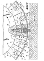
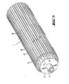
- Fig.-1 denotes a roller, as shown in Fig. 2 enlarged with details and in Fig. 3 schematically simplified perspective.
- Fig. 1 only the left end of the roller 1 is illustrated in the example, it being understood that there is a corresponding bearing of the roller at the opposite end.
- 2 denotes a shaft, which is connected to the roller 1 and serves to support it.
- the roller 1 is supported on the shaft 2 on a bearing frame 3 by means of bearings 4 on both sides. Outside the bearing 4, the shaft 2 projects into an electrical connection box 5 in which, in a known manner, a schematically illustrated slip ring 6 supplies the rotating parts of the roller with a power supply 1 is done.
- the roller 1 can be rotated in the bearing 4 via the shaft 2.
- an electric motor 7 is provided, which is mounted on the bearing frame 3 and drives a drive gear 9, which is connected to the shaft 2 in a rotationally fixed manner, with an output pinion 8 via a toothed belt or the like. In this way, the roller 1 can be rotated in the bearings 4.
- the storage rack 3 is guided up and down on columns 10 of a stationary portal, generally designated 11.
- a holding frame 12 with a cross member 13 is guided up and down on the columns 10.
- the bearing frame 3 is held on the holding frame 12 via pressure medium drives 14 in the form of, for example, pneumatic cylinders 15 which are mounted on the crossmember 13 and whose piston rods 16 act on the bearing frame 3 at 17.
- pressure medium drives 14 in the form of, for example, pneumatic cylinders 15 which are mounted on the crossmember 13 and whose piston rods 16 act on the bearing frame 3 at 17.
- the holding frame 12 is in turn connected via actuators 18 to a cross member 19 of the fixed portal 11.
- the actuators 18, for example in the form of threaded spindles 20, are actuated by an electric motor 21, for example in the form of a stepping motor and gear 22.
- the height of the crossmember 13 and the holding frame 12 can be finely adjusted in a desired position via the actuating drives 18.
- the piston rod 16 of the pressure medium drives 14 is extended, this results in a corresponding specific height position of the roller 1.
- the roller 1 can be lowered into this predetermined operating position or raised to a rest position. without changing the position of the holding frame 12 and thus canceling the set fine adjustment.
- the lower region of the roller 1 is shown in an end view and partly in section in the operating position.
- the roller 1 has a support body 23 in the form of a polygon, in the example in the form of a 20-corner, on the flat lateral surfaces 24 of which holders 25 for heating rods 26 are held by screws 27.
- the heating rods 26 have a bearing body 28 arranged in the interior of the holder 25 and also marking ribs 30 protruding from the peripheral surface of the roller 1, designated 29.
- the heating rods 26 consist of a suitable, good heat-conducting metal and have in the area of their bearing body 28 a round recess 31 in the example for receiving conventional tubular heaters 32 - similar to heating coils from immersion heaters.
- the heating rods 26 are divided in a plane 33 radial to the axis of the roller 1, the parts 26a and 26b of the heating rods 26 thus formed being connected to one another by suitable countersunk screws 34 and 35.
- the tubular heaters 32 After the tubular heaters 32 have been installed in the recess 31 of the two open parts 26a and 26b of the heating rods 26, the heating rods 26 are preassembled by inserting the screws 34 and 35 and inserted into the holder 25. Then the holders 25 are provided on their circumferential outer side with cover plates 36 which overlap shoulders 37 of the bearing body 28 of each heating element 26 and thus hold it securely in the holder 25.
- the holder 25 and the cover plates 36 consist of a suitable, poorly heat-conducting material such as a fibrous or fibrous press material based on asbestos or asbestos substitute in order to avoid heat losses of the heating rods 26 and the areas of the peripheral surface 29 on both sides of the marking ribs 30 to protect against heating and heat transfer to the mineral fiber material of the mineral fiber web designated 38. In this way, all sides of the heating rods 26 lying within the peripheral surface 29 of the roller 1 are surrounded by heat-insulating material.
- Each heating rod 26 has a recess 39 for receiving an earth cable. At least one of the heating rods 26 also has a recess 40 in the vicinity of its marking rib 30 for receiving a thermal sensor.
- the temperature control using the thermal sensor and the power supply to the tubular heater 32 is carried out via the slip rings 6 (see FIG. 1).
- temperature control using thermal sensors can also be dispensed with, and instead only the power supply to the tubular heating elements 32 can be regulated. In stationary operation, a certain temperature then results which is suitable for producing the markings, the optimum formation of the markings being able to be set by the degree of impression of the roller 1 in the mineral fiber web 38.
- the marking ribs 30 of the heating rods 26 and possibly the heating rods themselves extend only over part of the axial length of the roller 1, so that a plurality of marking ribs 30 form an interrupted line along a surface line of the roller 1 and at an axial distance are arranged from each other. If the length of the heating rods 26 is limited to the axial extent of the marking ribs 30, this results in a plurality of individual, shorter heating rods with easily controllable thermal expansions.
- the heating rods 26 can then be connected to one another through lines or a correspondingly circumferentially insulated piece of tubular heater 32 which connects the heating rods 26 approximately in an arc shape.
- the heating rods 26 pass over the entire axial length of the roller 1 and only between the protruding sections of the heating rods 26 designated as marking ribs 30, the gaps required to interrupt the marking are present, a very robust and stable construction results, in which the Tubular heating elements 32 are embedded in the heating rods 26 over their entire length.
- the mineral fiber web 38 is preferably of a type such as is explained in the context of the priority-establishing German patent application P 36 12 858.9-25.
- it may be an unclad mineral fiber web 38 with a width of 1200 mm, a nominal thickness of 100 mm and a length of 6 m.
- the bulk density may be between 10 and 30 kg / m, in particular between 14 3 and 25 kg / m, and in the specific example case 18 kg / m.
- Particularly suitable as a binder is phenolic resin in a proportion of 6 to 7% by weight of the dry binder in the product, the binder content of phenolic resin being 6.6% by weight (dry) in the example.
- the roller 1 In operation, with the piston rods 16 retracted, the roller 1 is set in rotation by the electric motor 7 above the surface of the mineral fiber web 38 denoted by 41, the heating rods 26 being preheated to a desired temperature, optionally monitored by the thermal sensors, by supplying current to the tubular heating elements 32.
- the rotation in the preheating phase ensures uniform heat losses of the individual heating rods 26 and marking ribs 30 and thus their uniform heating without individual temperature control on each individual heating rod 26.
- the piston rods 16 are extended and the roller 1 is lowered onto the surface 41 of the mineral fiber web 38, by means of the electric motor 21 and the actuators 18 can be used to fine-tune the height of the roller 1 over the mineral fiber web 38.
- the setting is appropriately chosen so that the marking ribs 30 on the circumference of the roller 1 press the surface 41 of the mineral fiber web 38 to form a trough 42.
- the surface 41 of the mineral fiber web 38 is typically uncovered, that is to say is formed by the mineral fiber tangle itself; however, the surface 41 can also have a lamination, for example in the form of a fleece based on mineral fibers or of other fibers.
- the marking rib 30 has a temperature of typically of the order of 400 ° C. and produces a zone of the decomposition of the binder in the mineral fiber web 38, indicated by dash-dotted lines, which is discolored.
- marking lines are formed on the surface 41 of the mineral fiber web 38, which extend transversely to the side edges of the mineral fiber web 41.
- the roller 1 can be continuously driven synchronously with the transport speed of the mineral fiber web 38.
- a DC motor is then expediently used as the electric motor 7.
- the electric motor 7 uses a three-phase motor, which is connected via a freewheel 44 to the output pinion 8, such that when the roller 1 is driven from the mineral fiber web 38, the rotational speed of the roller 1 can overtake that of the electric motor 7.
- the drive by the electric motor 7 is used exclusively to maintain a minimum rotational speed which is not critical in terms of the rotational speed in the raised rest position when the drive is removed from the mineral fiber web 38, in order to ensure uniform heating of the heating rods 26.
- the heat transfer conditions between the marking ribs 30 and the surface 41 of the mineral fiber web 38 can be adjusted in the manner described to form optimal marking lines. With a given transport speed and consistency of the mineral fiber web 38, however, such a fine adjustment can also be dispensed with, since it is then possible to work with a fixed presetting of the impression behavior of the roller 1 into the surface 41 of the mineral fiber web 38. In this way, the construction for mounting the roller 1 can be significantly simplified.
- the pressure medium drives 14 can be depressurized in the operating position, so that the roller simply with its own weight on the Mineral fiber web 38 rests.
- excessive penetration can be avoided by the fact that the marking ribs 30 do not protrude from the undisturbed circumferential surface 29 of the roller 1 by a few millimeters, in the example, approximately 8 mm, but rather lie within the undisturbed circumferential surface 29, so that these - for example in the form of cover plates 36 - helping to carry the weight and thus avoiding excessive local penetration.
- the illustrated embodiment with marking ribs 30 protruding from the peripheral surface 29 is particularly well suited for driving the roller 1 from the mineral fiber web 38.
Landscapes
- Engineering & Computer Science (AREA)
- Architecture (AREA)
- Civil Engineering (AREA)
- Structural Engineering (AREA)
- Physics & Mathematics (AREA)
- Acoustics & Sound (AREA)
- Electromagnetism (AREA)
- Treatment Of Fiber Materials (AREA)
- Nonwoven Fabrics (AREA)
- Treatments For Attaching Organic Compounds To Fibrous Goods (AREA)
- Application Of Or Painting With Fluid Materials (AREA)
- Materials For Medical Uses (AREA)
- Building Environments (AREA)
- Vehicle Interior And Exterior Ornaments, Soundproofing, And Insulation (AREA)
- Folding Of Thin Sheet-Like Materials, Special Discharging Devices, And Others (AREA)
- Polyoxymethylene Polymers And Polymers With Carbon-To-Carbon Bonds (AREA)
- Treatments Of Macromolecular Shaped Articles (AREA)
- Adhesives Or Adhesive Processes (AREA)
- Paper (AREA)
Priority Applications (1)
| Application Number | Priority Date | Filing Date | Title |
|---|---|---|---|
| AT87200792T ATE68418T1 (de) | 1986-04-16 | 1987-04-16 | Verfahren und vorrichtung zum aufbringen von markierungslinien auf eine bindemittelhaltige mineralfaserbahn. |
Applications Claiming Priority (2)
| Application Number | Priority Date | Filing Date | Title |
|---|---|---|---|
| DE3612858A DE3612858C1 (de) | 1986-04-16 | 1986-04-16 | Verfahren zum Einbau von in Rollenform vorliegendem Mineralfasermaterial in einen von seitlichen Stuetzen begrenzten langgestreckten Einbauraum sowie zur Durchfuehrung des Verfahrens geeignete Mineralfaserbahn und Verfahren zu deren Herstellung |
| DE3612858 | 1986-04-16 |
Publications (3)
| Publication Number | Publication Date |
|---|---|
| EP0244035A1 true EP0244035A1 (fr) | 1987-11-04 |
| EP0244035B1 EP0244035B1 (fr) | 1991-10-16 |
| EP0244035B2 EP0244035B2 (fr) | 1995-05-17 |
Family
ID=6298831
Family Applications (2)
| Application Number | Title | Priority Date | Filing Date |
|---|---|---|---|
| EP87902501A Pending EP0266382A1 (fr) | 1986-04-16 | 1987-04-16 | Procede et dispositif pour apposer des lignes de marquage sur une bande de fibres minerales contenant un liant |
| EP87200792A Expired - Lifetime EP0244035B2 (fr) | 1986-04-16 | 1987-04-16 | Procédé et dispositif pour obtenir des lignes de marquage sur une nappe de fibres minérales contenant un liant |
Family Applications Before (1)
| Application Number | Title | Priority Date | Filing Date |
|---|---|---|---|
| EP87902501A Pending EP0266382A1 (fr) | 1986-04-16 | 1987-04-16 | Procede et dispositif pour apposer des lignes de marquage sur une bande de fibres minerales contenant un liant |
Country Status (12)
| Country | Link |
|---|---|
| EP (2) | EP0266382A1 (fr) |
| AT (1) | ATE68418T1 (fr) |
| CA (1) | CA1302155C (fr) |
| CH (1) | CH660765A5 (fr) |
| DE (1) | DE3612858C1 (fr) |
| DK (1) | DK165398C (fr) |
| ES (1) | ES2026895T5 (fr) |
| FI (1) | FI875548A0 (fr) |
| GR (1) | GR3002922T3 (fr) |
| IE (1) | IE60391B1 (fr) |
| IT (1) | IT1216923B (fr) |
| WO (1) | WO1987006198A1 (fr) |
Cited By (3)
| Publication number | Priority date | Publication date | Assignee | Title |
|---|---|---|---|---|
| EP0795424A1 (fr) * | 1996-03-12 | 1997-09-17 | Pfleiderer Dämmstofftechnik GmbH & Co. | Dispositif et procédé pour obtenir des marquages sur un produit en fibres minérales |
| WO1998013541A1 (fr) * | 1996-09-28 | 1998-04-02 | Deutsche Rockwool Mineralwoll-Gmbh | Materiau isolant fibreux |
| WO1999029516A1 (fr) * | 1997-12-05 | 1999-06-17 | Seeber Engineering Gmbh | Dispositif pour imprimer par estampage des signes distinctifs sur des pieces mobiles |
Families Citing this family (6)
| Publication number | Priority date | Publication date | Assignee | Title |
|---|---|---|---|---|
| DE3908128A1 (de) * | 1989-03-13 | 1990-09-20 | Gruenzweig & Hartmann | Thermische markierungsvorrichtung fuer mineralwollebahnen sowie verfahren zum aufbringen von markierungen |
| DE3928741A1 (de) * | 1989-08-30 | 1991-03-07 | Gruenzweig & Hartmann | Schraegdach, insbesondere von altbauten, sowie daemmstoffbahn zu seiner daemmung und verfahren zu seiner herstellung |
| DE4341433A1 (de) * | 1993-12-04 | 1995-06-08 | Joma Daemmstoffwerk Josef Mang | Platte zur Wärmedämmung von Gebäuden |
| DE4447681C2 (de) * | 1994-04-29 | 2000-05-31 | Gruenzweig & Hartmann | Fassadendämmsystem |
| DE19903370A1 (de) * | 1999-01-28 | 2000-08-03 | Gruenzweig & Hartmann | Markierungen an insbesondere Mineralwollprodukten |
| US6644185B1 (en) * | 2000-11-06 | 2003-11-11 | Greydon Inc. | Flexographic rotary platen printing press |
Citations (5)
| Publication number | Priority date | Publication date | Assignee | Title |
|---|---|---|---|---|
| US3730081A (en) * | 1972-01-07 | 1973-05-01 | G Colledge | Rotory hot die embosser with tapered shaft and insulated embossing wheel |
| US4007767A (en) * | 1972-01-07 | 1977-02-15 | Colledgewood, Ltd. | Highspeed rotary branding process having increased die life |
| US4288968A (en) * | 1979-12-03 | 1981-09-15 | Fuji Machinery Co., Ltd. | End sealing device for a plastic film in a packaging apparatus |
| GB2084921A (en) * | 1980-09-12 | 1982-04-21 | Rexham Corp | Side sealing mechanism for a packaging machine |
| EP0101376A2 (fr) * | 1982-08-09 | 1984-02-22 | Isover Saint-Gobain | Nappe de matière isolante, en particulier en feutre de fibres minérales, comportant un parement collé, et procédé pour sa fabrication et pour son installation ou sa pose |
Family Cites Families (1)
| Publication number | Priority date | Publication date | Assignee | Title |
|---|---|---|---|---|
| DE3203624C2 (de) * | 1981-09-17 | 1990-02-15 | Deutsche Rockwool Mineralwoll-GmbH, 4390 Gladbeck | Platte aus Dämmstoffen, insbesondere Mineralfasern |
-
1986
- 1986-04-16 DE DE3612858A patent/DE3612858C1/de not_active Expired
- 1986-07-08 CH CH2755/86A patent/CH660765A5/de not_active IP Right Cessation
-
1987
- 1987-04-07 IT IT8720016A patent/IT1216923B/it active
- 1987-04-16 CA CA000535041A patent/CA1302155C/fr not_active Expired - Fee Related
- 1987-04-16 AT AT87200792T patent/ATE68418T1/de not_active IP Right Cessation
- 1987-04-16 ES ES87200792T patent/ES2026895T5/es not_active Expired - Lifetime
- 1987-04-16 WO PCT/EP1987/000208 patent/WO1987006198A1/fr not_active Ceased
- 1987-04-16 EP EP87902501A patent/EP0266382A1/fr active Pending
- 1987-04-16 IE IE100187A patent/IE60391B1/en not_active IP Right Cessation
- 1987-04-16 EP EP87200792A patent/EP0244035B2/fr not_active Expired - Lifetime
- 1987-12-16 FI FI875548A patent/FI875548A0/fi not_active IP Right Cessation
- 1987-12-16 DK DK660787A patent/DK165398C/da not_active IP Right Cessation
-
1991
- 1991-10-17 GR GR91401486T patent/GR3002922T3/el unknown
Patent Citations (5)
| Publication number | Priority date | Publication date | Assignee | Title |
|---|---|---|---|---|
| US3730081A (en) * | 1972-01-07 | 1973-05-01 | G Colledge | Rotory hot die embosser with tapered shaft and insulated embossing wheel |
| US4007767A (en) * | 1972-01-07 | 1977-02-15 | Colledgewood, Ltd. | Highspeed rotary branding process having increased die life |
| US4288968A (en) * | 1979-12-03 | 1981-09-15 | Fuji Machinery Co., Ltd. | End sealing device for a plastic film in a packaging apparatus |
| GB2084921A (en) * | 1980-09-12 | 1982-04-21 | Rexham Corp | Side sealing mechanism for a packaging machine |
| EP0101376A2 (fr) * | 1982-08-09 | 1984-02-22 | Isover Saint-Gobain | Nappe de matière isolante, en particulier en feutre de fibres minérales, comportant un parement collé, et procédé pour sa fabrication et pour son installation ou sa pose |
Cited By (4)
| Publication number | Priority date | Publication date | Assignee | Title |
|---|---|---|---|---|
| EP0795424A1 (fr) * | 1996-03-12 | 1997-09-17 | Pfleiderer Dämmstofftechnik GmbH & Co. | Dispositif et procédé pour obtenir des marquages sur un produit en fibres minérales |
| WO1998013541A1 (fr) * | 1996-09-28 | 1998-04-02 | Deutsche Rockwool Mineralwoll-Gmbh | Materiau isolant fibreux |
| WO1999029516A1 (fr) * | 1997-12-05 | 1999-06-17 | Seeber Engineering Gmbh | Dispositif pour imprimer par estampage des signes distinctifs sur des pieces mobiles |
| US6295923B1 (en) | 1997-12-05 | 2001-10-02 | Seeber Engineering Gmbh | Device with eccentric stamping wheel for stamping moving parts |
Also Published As
| Publication number | Publication date |
|---|---|
| EP0244035B2 (fr) | 1995-05-17 |
| IT8720016A0 (it) | 1987-04-07 |
| DK660787A (da) | 1987-12-16 |
| IE60391B1 (en) | 1994-07-13 |
| IE871001L (en) | 1987-10-16 |
| EP0244035B1 (fr) | 1991-10-16 |
| EP0266382A1 (fr) | 1988-05-11 |
| CH660765A5 (de) | 1987-06-15 |
| ES2026895T3 (es) | 1992-05-16 |
| IT1216923B (it) | 1990-03-14 |
| FI875548A7 (fi) | 1987-12-16 |
| DK165398C (da) | 1993-04-05 |
| DK660787D0 (da) | 1987-12-16 |
| FI875548A0 (fi) | 1987-12-16 |
| DE3612858C1 (de) | 1987-10-01 |
| DK165398B (da) | 1992-11-23 |
| ES2026895T5 (es) | 1995-08-16 |
| CA1302155C (fr) | 1992-06-02 |
| WO1987006198A1 (fr) | 1987-10-22 |
| GR3002922T3 (en) | 1993-01-25 |
| ATE68418T1 (de) | 1991-11-15 |
Similar Documents
| Publication | Publication Date | Title |
|---|---|---|
| EP0089494B1 (fr) | Procédé et dispositif pour gaufrer une bande flexible continue | |
| DE102010004781B4 (de) | Trenn- und Abisoliereinrichtung für eine Kabelverarbeitungsmaschine | |
| DE2923067C2 (de) | Temperaturhaltehaube für eine Strangbrennschneidvorrichtung | |
| EP0244035B2 (fr) | Procédé et dispositif pour obtenir des lignes de marquage sur une nappe de fibres minérales contenant un liant | |
| DE3713108C2 (fr) | ||
| EP0829322B1 (fr) | Cisaille à grande vitesse pour le tronçonnage de feuillard laminé | |
| EP0694019B1 (fr) | Dispositif pour separer un produit d'une bande defilant en continu | |
| DE3908128A1 (de) | Thermische markierungsvorrichtung fuer mineralwollebahnen sowie verfahren zum aufbringen von markierungen | |
| DE3337913A1 (de) | Kontinuierlich arbeitende presse zum pressen einer vorlaufenden werkstoffbahn | |
| DE2721980C3 (de) | Prägefolien-Zuführvorrichtung für eine Prägemaschine | |
| EP0870610A1 (fr) | Dispositif d'enfilage pour une machine rotative d'impression | |
| DE2520462A1 (de) | Verfahren zur kontinuierlichen herstellung von isolierenden schalenkoerpern und vorrichtung zur durchfuehrung des verfahrens | |
| CH649316A5 (de) | Verfahren und vorrichtung zum verbinden von halteelementen oder stromschienen mit anoden oder kathoden. | |
| EP0795424A1 (fr) | Dispositif et procédé pour obtenir des marquages sur un produit en fibres minérales | |
| DE3602523C1 (de) | Widerlager fuer ein Rohrwalzwerk | |
| EP1218562A1 (fr) | Procede de traitement thermique de billettes metalliques | |
| EP0179395A1 (fr) | Dispositif de couchage pour installation de carton ondulé | |
| EP2789731A1 (fr) | Dispositif de thermofixation d'une bande textile présentant un matériau fusible | |
| DE2935029B1 (de) | Verfahren zum Bewegen des oder der Brennschneidaggregate beim Brennschneiden und Vorrichtung hierfuer | |
| DE2530871A1 (de) | Verfahren und vorrichtung zur kontinuierlichen herstellung von gewellten bahnen oder tafeln | |
| DE3033148A1 (de) | Maschine zum zerschneiden von textilmaterialrollen | |
| DE1704968A1 (de) | Verfahren und Vorrichtung zur Ausbildung eines Oberflaechenmusters | |
| DE2628937B2 (de) | Mit einer Abschervorrichtung versehene Wickel- bzw. Winde-Einrichtung zum Herstellen von Schraubenfeldern | |
| DE3001596C2 (de) | Kurbelgetriebe | |
| DE1602404C (de) | Verfahren und Vorrichtung zum Herstellen von Rohrblechplatten mit gleichen Rohrverlaufmustern |
Legal Events
| Date | Code | Title | Description |
|---|---|---|---|
| PUAI | Public reference made under article 153(3) epc to a published international application that has entered the european phase |
Free format text: ORIGINAL CODE: 0009012 |
|
| 17P | Request for examination filed |
Effective date: 19870515 |
|
| AK | Designated contracting states |
Kind code of ref document: A1 Designated state(s): ES GR |
|
| XX | Miscellaneous (additional remarks) |
Free format text: VERBUNDEN MIT 87902501.3/0266382 (EUROPAEISCHE ANMELDENUMMER/VEROEFFENTLICHUNGSNUMMER) DURCH ENTSCHEIDUNG VOM 16.12.88. |
|
| 17Q | First examination report despatched |
Effective date: 19890926 |
|
| GRAA | (expected) grant |
Free format text: ORIGINAL CODE: 0009210 |
|
| AK | Designated contracting states |
Kind code of ref document: B1 Designated state(s): AT BE CH ES FR GB GR IT LI LU NL SE |
|
| REF | Corresponds to: |
Ref document number: 68418 Country of ref document: AT Date of ref document: 19911115 Kind code of ref document: T |
|
| XX | Miscellaneous (additional remarks) |
Free format text: VERBUNDEN MIT 87902501.3/0266382 (EUROPAEISCHE ANMELDENUMMER/VEROEFFENTLICHUNGSNUMMER) DURCH ENTSCHEIDUNG VOM 16.12.88. |
|
| GBT | Gb: translation of ep patent filed (gb section 77(6)(a)/1977) | ||
| ITF | It: translation for a ep patent filed | ||
| ET | Fr: translation filed | ||
| PLBI | Opposition filed |
Free format text: ORIGINAL CODE: 0009260 |
|
| 26 | Opposition filed |
Opponent name: N.V. OWENS-CORNING S.A. Effective date: 19920707 |
|
| REG | Reference to a national code |
Ref country code: GR Ref legal event code: FG4A Free format text: 3002922 |
|
| NLR1 | Nl: opposition has been filed with the epo |
Opponent name: N.V. OWENS-CORNING S.A. |
|
| EPTA | Lu: last paid annual fee | ||
| EAL | Se: european patent in force in sweden |
Ref document number: 87200792.7 |
|
| PUAH | Patent maintained in amended form |
Free format text: ORIGINAL CODE: 0009272 |
|
| STAA | Information on the status of an ep patent application or granted ep patent |
Free format text: STATUS: PATENT MAINTAINED AS AMENDED |
|
| ITF | It: translation for a ep patent filed | ||
| 27A | Patent maintained in amended form |
Effective date: 19950517 |
|
| AK | Designated contracting states |
Kind code of ref document: B2 Designated state(s): AT BE CH ES FR GB GR IT LI LU NL SE |
|
| PG25 | Lapsed in a contracting state [announced via postgrant information from national office to epo] |
Ref country code: GR Free format text: THE PATENT HAS BEEN ANNULLED BY A DECISION OF A NATIONAL AUTHORITY Effective date: 19950609 |
|
| REG | Reference to a national code |
Ref country code: CH Ref legal event code: AEN |
|
| NLR2 | Nl: decision of opposition | ||
| GBTA | Gb: translation of amended ep patent filed (gb section 77(6)(b)/1977) |
Effective date: 19950621 |
|
| ET3 | Fr: translation filed ** decision concerning opposition | ||
| REG | Reference to a national code |
Ref country code: ES Ref legal event code: DC2A Kind code of ref document: T5 Effective date: 19950816 |
|
| REG | Reference to a national code |
Ref country code: GR Ref legal event code: FG4A Free format text: 3016412 |
|
| NLR3 | Nl: receipt of modified translations in the netherlands language after an opposition procedure | ||
| PGFP | Annual fee paid to national office [announced via postgrant information from national office to epo] |
Ref country code: GR Payment date: 19980430 Year of fee payment: 12 |
|
| REG | Reference to a national code |
Ref country code: GB Ref legal event code: IF02 |
|
| PGFP | Annual fee paid to national office [announced via postgrant information from national office to epo] |
Ref country code: SE Payment date: 20060330 Year of fee payment: 20 |
|
| PGFP | Annual fee paid to national office [announced via postgrant information from national office to epo] |
Ref country code: ES Payment date: 20060404 Year of fee payment: 20 |
|
| PGFP | Annual fee paid to national office [announced via postgrant information from national office to epo] |
Ref country code: GB Payment date: 20060410 Year of fee payment: 20 |
|
| PGFP | Annual fee paid to national office [announced via postgrant information from national office to epo] |
Ref country code: FR Payment date: 20060418 Year of fee payment: 20 |
|
| PGFP | Annual fee paid to national office [announced via postgrant information from national office to epo] |
Ref country code: CH Payment date: 20060421 Year of fee payment: 20 |
|
| PGFP | Annual fee paid to national office [announced via postgrant information from national office to epo] |
Ref country code: LU Payment date: 20060424 Year of fee payment: 20 Ref country code: BE Payment date: 20060424 Year of fee payment: 20 Ref country code: AT Payment date: 20060424 Year of fee payment: 20 |
|
| PGFP | Annual fee paid to national office [announced via postgrant information from national office to epo] |
Ref country code: NL Payment date: 20060427 Year of fee payment: 20 |
|
| PGFP | Annual fee paid to national office [announced via postgrant information from national office to epo] |
Ref country code: IT Payment date: 20060430 Year of fee payment: 20 |
|
| PG25 | Lapsed in a contracting state [announced via postgrant information from national office to epo] |
Ref country code: NL Free format text: LAPSE BECAUSE OF EXPIRATION OF PROTECTION Effective date: 20070416 |
|
| PG25 | Lapsed in a contracting state [announced via postgrant information from national office to epo] |
Ref country code: ES Free format text: LAPSE BECAUSE OF EXPIRATION OF PROTECTION Effective date: 20070417 |
|
| REG | Reference to a national code |
Ref country code: GB Ref legal event code: PE20 |
|
| REG | Reference to a national code |
Ref country code: CH Ref legal event code: PL |
|
| NLV7 | Nl: ceased due to reaching the maximum lifetime of a patent |
Effective date: 20070416 |
|
| EUG | Se: european patent has lapsed | ||
| REG | Reference to a national code |
Ref country code: ES Ref legal event code: FD2A Effective date: 20070417 |
|
| PG25 | Lapsed in a contracting state [announced via postgrant information from national office to epo] |
Ref country code: GB Free format text: LAPSE BECAUSE OF EXPIRATION OF PROTECTION Effective date: 20070415 |
|
| BE20 | Be: patent expired |
Owner name: *ISOVER SAINT-GOBAIN Effective date: 20070416 |