EP0245057A2 - Dispositif de refroidissement d'hélium - Google Patents
Dispositif de refroidissement d'hélium Download PDFInfo
- Publication number
- EP0245057A2 EP0245057A2 EP87303959A EP87303959A EP0245057A2 EP 0245057 A2 EP0245057 A2 EP 0245057A2 EP 87303959 A EP87303959 A EP 87303959A EP 87303959 A EP87303959 A EP 87303959A EP 0245057 A2 EP0245057 A2 EP 0245057A2
- Authority
- EP
- European Patent Office
- Prior art keywords
- helium
- heat
- liquid
- cooling apparatus
- container
- Prior art date
- Legal status (The legal status is an assumption and is not a legal conclusion. Google has not performed a legal analysis and makes no representation as to the accuracy of the status listed.)
- Granted
Links
Images

Classifications
-
- H—ELECTRICITY
- H01—ELECTRIC ELEMENTS
- H01F—MAGNETS; INDUCTANCES; TRANSFORMERS; SELECTION OF MATERIALS FOR THEIR MAGNETIC PROPERTIES
- H01F6/00—Superconducting magnets; Superconducting coils
- H01F6/04—Cooling
-
- F—MECHANICAL ENGINEERING; LIGHTING; HEATING; WEAPONS; BLASTING
- F25—REFRIGERATION OR COOLING; COMBINED HEATING AND REFRIGERATION SYSTEMS; HEAT PUMP SYSTEMS; MANUFACTURE OR STORAGE OF ICE; LIQUEFACTION SOLIDIFICATION OF GASES
- F25B—REFRIGERATION MACHINES, PLANTS OR SYSTEMS; COMBINED HEATING AND REFRIGERATION SYSTEMS; HEAT PUMP SYSTEMS
- F25B2400/00—General features or devices for refrigeration machines, plants or systems, combined heating and refrigeration systems or heat-pump systems, i.e. not limited to a particular subgroup of F25B
- F25B2400/17—Re-condensers
Definitions
- the present invention relates to a helium cooling apparatus in which gas helium in a liquid-helium container is cooled to be recondensed, and more particularly to a helium cooling apparatus in which a condensation-heat exchanger in the liquid-helium container has an improved heat transfer coefficient.
- a liquid-helium container for cooling a superconducting coil and the like is disposed adiabatically in a cryostat.
- a helium cooling apparatus is used to cool and recondense gas helium in the liquid-helium container.
- the cooling apparatus comprises a refrigerator for cooling a refrigerant, and a condensation-heat exchanger for evaporating the refrigerant to cool the gas helium.
- helium cooling apparatuses can be classified into two types. In one type, the refrigerator is incorporated in the cryostat, and the condensation-heat exchanger is located in the liquid-helium container.
- an exclusive-use cylindrical member extends from an exclusive-use port in the liquid-helium container to the outside of the cryostat.
- the heat exchanger is inserted into the helium container through the port and the cylindrical member for exclusive use.
- the refrigerator is disposed inside the cylindrical member or outside the cryostat.
- the refrigerator In maintaining the refrigerator, in the case of the first type, the refrigerator must be disassembled, repaired, and reassembled after the temperature of the helium in the liquid-helium container is raised. In this type, therefore, the refrigerator cannot be maintained with ease.
- the helium cooling apparatus can be mounted or demounted easily, without causing the liquid helium in the container to be discharged. In the second type, therefore, the refrigerator can be maintained without increasing the temperature of the helium in the helium container.
- the helium cooling apparatus of the second type has an advantage over the first type.
- the performance of the helium cooling apparatus depends on that of the refrigerator and the heat transfer coefficient of the condensation-heat exchanger. In order to improve the performance of the cooling apparatus, therefore, the heat transfer coefficient of the exchanger must be improved. Thus, the heat-transfer area of the heat exchanger is expected to be increased.
- the diameters of the port and the cylindrical member for exclusive use depend on the size of the condensation-heat exchanger. If the heat-transfer area of the heat exchanger becomes greater, therefore, the diameter of the exchanger, and hence, those of the port and the cylindrical member, are increased in proportion. Thus, the amount of heat introduced into the liquid-helium container, through the port and the cylindrical member, increases. The introduced heat lowers the thermal efficiency of the whole cooling apparatus.
- the object of the present invention is to provide a helium cooling apparatus, in which a condensation-heat exchanger enjoys an improved heat transfer coefficient and a reduced diameter, so that a port of a liquid-helium container, through which the heat exchanger is inserted into the container, can be reduced in diameter.
- a helium cooling apparatus comprises a refrigerator for cooling a refrigerant.
- the refrigerator is connected with the proximal end of a transfer line, which is used to transport the refrigerant.
- a port with a predetermined diameter is formed in a liquid-helium container which contains liquid helium.
- a condensation-heat exchanger which is connected to the distal end of the transfer line, is inserted into the liquid-helium container through the port.
- a heat-transfer surface of the heat exchanger is formed with a plurality of grooves extending in the gravitational direction. The refrigerant is evaporated in the heat exchanger, so that helium gas in the liquid-helium container is cooled to be recondensed.
- the condensation-heat exchanger of the invention is smaller in diameter than the prior art heat exchanger.
- the port of the liquid-helium container, through which the exchanger is inserted into the container need not have a large diameter. Therefore, the amount of heat entering the container through the port is very small. Since the heat exchanger is small-sized, moreover, the port for the insertion thereof need not always be an exclusive one.
- the condensation-heat exchanger according to the present invention may be used also in a liquid-helium container without an exclusive-use port.
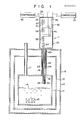
- cryostat 2 which incorporates helium cooling apparatus l according to the present invention.
- Cryostat 2 comprises liquid-helium container ll, heat-shielding plate l2, and vacuum container l3.
- Container ll is filled with liquid helium l4.
- Object l5 of cooling e.g., superconducting magnet
- Heat-shielding plate l2 is cooled by liquid nitrogen, for example.
- Liquid-helium container ll has port l8, to which is attached liquid-helium injection pipe l6 which opens to the outside.
- Container ll is fitted with helium gas recovery pipe l7 which opens to the outside. After liquid helium l4 is put into container ll, injection pipe l6 is closed. When helium l4 is evaporated by heat introduced into container ll, the resulting vapor is recovered through recovery pipe l7.
- Helium cooling apparatus l comprises refrigerator 2l for cooling gas helium as a refrigerant, condensation-heat exchanger 24 for evaporating the refrigerant, thereby cooling the inside of liquid-helium container ll, and transfer line 23 connecting refrigerator 2l and heat exchanger 24.
- Refrigerator 2l includes first and second cooling systems 3l and 32, both of which are closed-cycle systems.
- First cooling system 3l has three heat exchangers 33, 34 and 35.
- Exchanger 33 is connected to compressor 36.
- Outgoing line 38 which extends from compressor 36, is connected to Joule-Thomson valve 37 via heat exchangers 33, 34 and 35.
- Return line 39 which extends from transfer line 23, is connected to compressor 36 via heat exchangers 35, 34 and 33.
- the refrigerant flowing through outgoing line 38 is cooled by the refrigerant flowing through return line 39.
- the refrigerant in line 38 is cooled by second cooling system 32, which has two heat exchangers 40 and 4l.
- Exchanger 40 is connected to compressor 42.
- the refrigerant flowing through outgoing line 38 is cooled further by exchangers 40 and 4l.
- Transfer line 23 is composed of inner and outer pipes 43 and 44. Outgoing and return lines 38 and 39 are connected to pipes 43 and 44, respectively. Thus, the refrigerant is fed through inner pipe 43, and is evaporated by condensation-heat exchanger 24, and then returned through outer pipe 44.
- the outside diameter of transfer line 23 is smaller than the inside diameter of liquid-helium injection pipe l6.
- Condensation-heat exchanger 24 is attached to the distal end of transfer line 23.
- the outside diameter of heat exchanger 24 is substantially equal to that of line 23.
- Exchanger 24 is located in a helium gas region inside liquid-helium container ll.
- Inner and outer pipes 38 and 39 of transfer line 23 terminate in a predetermined space inside heat exchanger 24. Within this space, the refrigerant is evaporated, thereby cooling a heat-transfer surface of the heat exchanger.
- exchanger 24 is formed from oxygen-free copper having a good thermal conductivity.
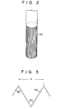
- grooves 50 are formed on the peripheral surface or heat-transfer surface of heat exchanger 24, extending in the axial or gravitational direction. These grooves will be described in detail later.
- the helium cooling apparatus of the invention cools the helium in the liquid-helium container as follows.
- liquid-helium container ll When helium gas recovery pipe l7 is closed, liquid-helium container ll is sealed hermetically. Meanwhile, seal member 25 is used to seal the gap between liquid-helium injection pipe l6 and transfer line 23. If container ll is left as it is, in this state, the liquid helium therein is evaporated, so that the pressure inside the container increases.
- compressors 36 and 42 are actuated to drive helium cooling apparatus l.
- the refrigerant starts to flow through outgoing line 38.
- the refrigerant whose temperature is about 300 K at the start, is cooled to about 60 K by heat exchangers 33 and 40. Thereafter, it is cooled further to about l6 K by heat exchangers 34 and 4l, and then to about 5 K by heat exchanger 35.
- the refrigerant is subjected to Joule-Thomson expansion by Joule-Thomson valve 37, so that its pressure is lowered to about l atm.
- the refrigerant at a pressure of about l atm.
- grooves 50 are formed on the heat-transfer surface so as to extend in the gravitational direction. Therefore, a wide heat-transfer area can be secured, and the liquid helium adhering to the transfer surface can drop along grooves 50. Thus, the condensation-heat transfer coefficient of the cooling device is improved considerably. The action of the liquid helium adhering to grooves 50 will be described in detail later.
- liquid-helium container ll is kept constant.
- Liquid helium l4 does not change in quantity, and the object of cooling is cooled continuously for a long period of time.
- each groove 50 on the heat-transfer surface is triangular in shape.
- the bottom and each edge top of groove 50 are acute-angled.
- the distance between the two edge tops of each groove 50 is referred to as pitch P.
- the angle formed by the bottom of groove 50 is ⁇ l, while the angle formed by each edge top is ⁇ 2.
- Angles ⁇ l and ⁇ 2 are substantially equal.
- the inventors hereof conducted an experiment to examine the heat transfer coefficient of the condensation-heat exchanger, while variously changing pitch P and angles ⁇ l and ⁇ 2.
- Fig. 4 shows an experiment result obtained with use of varying pitches.
- the curve of Fig. 4 represents the relationship between pitch P and value h/h0, where h0 is the condensation-heat transfer coefficient obtained without any grooves on the heat-transfer surface, and h is the heat transfer coefficient obtained when pitch P is changed as aforesaid.
- the curve of Fig. 4 indicates a transition of transfer coefficient h on the assumption that h0 is l.
- coefficient h is about 2.5 times as high as coefficient h0.
- the heat transfer coefficient of heat exchanger ll can be improved considerably by using pitch P within the aforesaid range.
- the pitch of grooves 50 ranges from 800 to l,200 ⁇ m
- the condensed liquid helium adheres only to the bottom portion of each groove, as shown in Fig. 5. Therefore, the edge tops of each groove 50 are exposed from the liquid helium, and are in contact with the helium gas in liquid-helium container ll. Accordingly, the heat-transfer surface of the grooves cannot be covered with the condensed helium, so that a wide heat-transfer area can be secured. Thus, the heat transfer coefficient of the heat-transfer surface is improved considerably.
- the inventors hereof also conducted an experiment in which angles ⁇ l and ⁇ 2 at the bottom and the edge top were changed variously, while keeping pitch P within the aforesaid range.
- the heat transfer coefficient of condensation-heat exchanger ll was examined with angles ⁇ l and ⁇ 2 ranging from 30° to 70°. Thereupon, it was indicated that the heat transfer coefficient is constant without regard to bottom angle ⁇ l.
- the condensation-heat transfer coefficient cannot be influenced by the angles at the edge top or the bottom of grooves 50.
- the heat exchanger of the invention is smaller in diameter than the prior art heat exchanger.
- the port of the liquid-helium container, through which the exchanger is inserted into the container need not have a large diameter. Therefore, the amount of heat entering the container through the port is very small. Since the heat exchanger is small-sized, moreover, the port for the insertion thereof need not always be an exclusive one.
- the condensation-heat exchanger according to the present invention may be used also in a liquid-helium container without an exclusive-use port.
- each groove 50 need not always be acute-angled. Alternatively, it may be arcuate in shape, as shown in Fig. 7.
Landscapes
- Engineering & Computer Science (AREA)
- Power Engineering (AREA)
- Separation By Low-Temperature Treatments (AREA)
- Containers, Films, And Cooling For Superconductive Devices (AREA)
- Polarising Elements (AREA)
Applications Claiming Priority (2)
| Application Number | Priority Date | Filing Date | Title |
|---|---|---|---|
| JP61103408A JPH0730963B2 (ja) | 1986-05-06 | 1986-05-06 | ヘリウム冷却装置 |
| JP103408/86 | 1986-05-06 |
Publications (3)
| Publication Number | Publication Date |
|---|---|
| EP0245057A2 true EP0245057A2 (fr) | 1987-11-11 |
| EP0245057A3 EP0245057A3 (en) | 1988-09-14 |
| EP0245057B1 EP0245057B1 (fr) | 1990-08-08 |
Family
ID=14353224
Family Applications (1)
| Application Number | Title | Priority Date | Filing Date |
|---|---|---|---|
| EP87303959A Expired EP0245057B1 (fr) | 1986-05-06 | 1987-05-01 | Dispositif de refroidissement d'hélium |
Country Status (4)
| Country | Link |
|---|---|
| US (1) | US4756167A (fr) |
| EP (1) | EP0245057B1 (fr) |
| JP (1) | JPH0730963B2 (fr) |
| DE (1) | DE3764158D1 (fr) |
Cited By (2)
| Publication number | Priority date | Publication date | Assignee | Title |
|---|---|---|---|---|
| WO1989006333A1 (fr) * | 1988-01-06 | 1989-07-13 | Helix Technology Corporation | Recondenseur eloigne a puits thermique a temperature intermediaire |
| WO2010029456A3 (fr) * | 2008-09-09 | 2010-10-07 | Koninklijke Philips Electronics, N.V. | Échangeur de chaleur horizontal nervuré pour réfrigération avec recondensation cryogénique |
Families Citing this family (10)
| Publication number | Priority date | Publication date | Assignee | Title |
|---|---|---|---|---|
| JPS6456153A (en) * | 1987-08-27 | 1989-03-03 | Yoshikage Oda | Low-temperature cold reserving device |
| JPH0728531Y2 (ja) * | 1989-02-01 | 1995-06-28 | ダイキン工業株式会社 | 極低温冷凍機 |
| JP2821241B2 (ja) * | 1990-06-08 | 1998-11-05 | 株式会社日立製作所 | 液化冷凍機付きクライオスタツト |
| US5613367A (en) * | 1995-12-28 | 1997-03-25 | General Electric Company | Cryogen recondensing superconducting magnet |
| CA2313480C (fr) * | 1997-12-12 | 2008-02-05 | Magnetic Imaging Technologies, Inc. | Accumulateurs de gaz polarises et chemises de rechauffage, procedes associes de decongelation et recuperation des gaz et produits gazeux obtenus |
| DE10251449B4 (de) * | 2001-11-21 | 2004-12-30 | Siemens Ag | Kryostat |
| CN109945596B (zh) * | 2019-03-05 | 2024-01-16 | 中国工程物理研究院激光聚变研究中心 | 温度梯度型低温环境制备装置 |
| JP7530185B2 (ja) * | 2020-02-25 | 2024-08-07 | 住友重機械工業株式会社 | 極低温冷凍機および極低温システム |
| CN114171281B (zh) * | 2022-02-14 | 2022-05-17 | 宁波健信核磁技术有限公司 | 一种超导磁体加热系统 |
| DE102023212894B8 (de) | 2023-12-18 | 2025-04-30 | Bruker Switzerland Ag | Vorrichtung und Verfahren zum Transfer von flüssigem Helium in einen Anwendungskryostaten |
Family Cites Families (5)
| Publication number | Priority date | Publication date | Assignee | Title |
|---|---|---|---|---|
| US2831549A (en) * | 1954-08-31 | 1958-04-22 | Westinghouse Electric Corp | Isolation trap |
| US4159739A (en) * | 1977-07-13 | 1979-07-03 | Carrier Corporation | Heat transfer surface and method of manufacture |
| US4543794A (en) * | 1983-07-26 | 1985-10-01 | Kabushiki Kaisha Toshiba | Superconducting magnet device |
| AU548348B2 (en) * | 1983-12-21 | 1985-12-05 | Air Products And Chemicals Inc. | Finned heat exchanger |
| JPS60259870A (ja) * | 1984-06-05 | 1985-12-21 | 株式会社東芝 | 磁気冷凍装置 |
-
1986
- 1986-05-06 JP JP61103408A patent/JPH0730963B2/ja not_active Expired - Lifetime
-
1987
- 1987-04-28 US US07/043,445 patent/US4756167A/en not_active Expired - Lifetime
- 1987-05-01 EP EP87303959A patent/EP0245057B1/fr not_active Expired
- 1987-05-01 DE DE8787303959T patent/DE3764158D1/de not_active Expired - Lifetime
Cited By (3)
| Publication number | Priority date | Publication date | Assignee | Title |
|---|---|---|---|---|
| WO1989006333A1 (fr) * | 1988-01-06 | 1989-07-13 | Helix Technology Corporation | Recondenseur eloigne a puits thermique a temperature intermediaire |
| WO2010029456A3 (fr) * | 2008-09-09 | 2010-10-07 | Koninklijke Philips Electronics, N.V. | Échangeur de chaleur horizontal nervuré pour réfrigération avec recondensation cryogénique |
| US9494359B2 (en) | 2008-09-09 | 2016-11-15 | Koninklijke Philips N.V. | Horizontal finned heat exchanger for cryogenic recondensing refrigeration |
Also Published As
| Publication number | Publication date |
|---|---|
| US4756167A (en) | 1988-07-12 |
| JPS62261866A (ja) | 1987-11-14 |
| EP0245057B1 (fr) | 1990-08-08 |
| DE3764158D1 (de) | 1990-09-13 |
| JPH0730963B2 (ja) | 1995-04-10 |
| EP0245057A3 (en) | 1988-09-14 |
Similar Documents
| Publication | Publication Date | Title |
|---|---|---|
| EP0245057A2 (fr) | Dispositif de refroidissement d'hélium | |
| US5381666A (en) | Cryostat with liquefaction refrigerator | |
| US4375157A (en) | Downhole thermoelectric refrigerator | |
| US5701751A (en) | Apparatus and method for actively cooling instrumentation in a high temperature environment | |
| CA1312209C (fr) | Recondenseur eloigne a source de froid a temperature intermediaire | |
| CN102971594A (zh) | 用于使用静态和移动气体来控制低温的低温恒温器中的温度的方法和设备 | |
| US3430455A (en) | Thermal switch for cryogenic apparatus | |
| US20090293504A1 (en) | Refrigeration installation having a warm and a cold connection element and having a heat pipe which is connected to the connection elements | |
| JP4040626B2 (ja) | 冷凍機の取付方法及び装置 | |
| US20070089432A1 (en) | Cryostat configuration with cryocooler | |
| US5463872A (en) | High performance thermal interface for low temperature electronic modules | |
| JPH08222429A (ja) | 極低温装置 | |
| JPS6294769A (ja) | 二段熱カツプリング | |
| US5454228A (en) | Refrigeration system for fluid chilling packages | |
| US4593532A (en) | Evaporation-cooled gas insulated electrical apparatus | |
| JP2006343075A (ja) | 機械式冷凍機とジュール・トムソン膨張を用いた極低温冷凍機 | |
| Hakuraku et al. | Thermal design and tests of a subcooled superfluid helium refrigerator | |
| US4030900A (en) | Cooling device | |
| CN87213525U (zh) | 采用分离式热管的半导体制冷装置 | |
| WO2021176604A1 (fr) | Dispositif à électro-aimant supraconducteur | |
| JPS6138363A (ja) | ヘリウム冷凍装置 | |
| Cowans et al. | Continuous Cryogenic Refrigeration for Three to Five Micron Infrared Systems | |
| JP3465195B2 (ja) | クライオポンプ | |
| Ishige et al. | 4. 2K Refrigerator for SQUID Magnetometer | |
| JPH08136170A (ja) | ヒートパイプ式冷却器 |
Legal Events
| Date | Code | Title | Description |
|---|---|---|---|
| PUAI | Public reference made under article 153(3) epc to a published international application that has entered the european phase |
Free format text: ORIGINAL CODE: 0009012 |
|
| AK | Designated contracting states |
Kind code of ref document: A2 Designated state(s): DE GB NL |
|
| 17P | Request for examination filed |
Effective date: 19880204 |
|
| PUAL | Search report despatched |
Free format text: ORIGINAL CODE: 0009013 |
|
| AK | Designated contracting states |
Kind code of ref document: A3 Designated state(s): DE GB NL |
|
| 17Q | First examination report despatched |
Effective date: 19890201 |
|
| GRAA | (expected) grant |
Free format text: ORIGINAL CODE: 0009210 |
|
| AK | Designated contracting states |
Kind code of ref document: B1 Designated state(s): DE GB NL |
|
| REF | Corresponds to: |
Ref document number: 3764158 Country of ref document: DE Date of ref document: 19900913 |
|
| PLBE | No opposition filed within time limit |
Free format text: ORIGINAL CODE: 0009261 |
|
| STAA | Information on the status of an ep patent application or granted ep patent |
Free format text: STATUS: NO OPPOSITION FILED WITHIN TIME LIMIT |
|
| 26N | No opposition filed | ||
| PGFP | Annual fee paid to national office [announced via postgrant information from national office to epo] |
Ref country code: DE Payment date: 19990507 Year of fee payment: 13 |
|
| PGFP | Annual fee paid to national office [announced via postgrant information from national office to epo] |
Ref country code: NL Payment date: 19990531 Year of fee payment: 13 |
|
| PG25 | Lapsed in a contracting state [announced via postgrant information from national office to epo] |
Ref country code: NL Free format text: LAPSE BECAUSE OF NON-PAYMENT OF DUE FEES Effective date: 20001201 |
|
| NLV4 | Nl: lapsed or anulled due to non-payment of the annual fee |
Effective date: 20001201 |
|
| PG25 | Lapsed in a contracting state [announced via postgrant information from national office to epo] |
Ref country code: DE Free format text: LAPSE BECAUSE OF NON-PAYMENT OF DUE FEES Effective date: 20010301 |
|
| PGFP | Annual fee paid to national office [announced via postgrant information from national office to epo] |
Ref country code: GB Payment date: 20010425 Year of fee payment: 15 |
|
| REG | Reference to a national code |
Ref country code: GB Ref legal event code: IF02 |
|
| PG25 | Lapsed in a contracting state [announced via postgrant information from national office to epo] |
Ref country code: GB Free format text: LAPSE BECAUSE OF NON-PAYMENT OF DUE FEES Effective date: 20020501 |
|
| GBPC | Gb: european patent ceased through non-payment of renewal fee |
Effective date: 20020501 |