EP0246081A2 - Processing paper and other webs - Google Patents
Processing paper and other webs Download PDFInfo
- Publication number
- EP0246081A2 EP0246081A2 EP87304243A EP87304243A EP0246081A2 EP 0246081 A2 EP0246081 A2 EP 0246081A2 EP 87304243 A EP87304243 A EP 87304243A EP 87304243 A EP87304243 A EP 87304243A EP 0246081 A2 EP0246081 A2 EP 0246081A2
- Authority
- EP
- European Patent Office
- Prior art keywords
- web
- printing
- reel
- cartridges
- cylinder
- Prior art date
- Legal status (The legal status is an assumption and is not a legal conclusion. Google has not performed a legal analysis and makes no representation as to the accuracy of the status listed.)
- Granted
Links
Images


Classifications
-
- B—PERFORMING OPERATIONS; TRANSPORTING
- B65—CONVEYING; PACKING; STORING; HANDLING THIN OR FILAMENTARY MATERIAL
- B65H—HANDLING THIN OR FILAMENTARY MATERIAL, e.g. SHEETS, WEBS, CABLES
- B65H45/00—Folding thin material
- B65H45/12—Folding articles or webs with application of pressure to define or form crease lines
-
- B—PERFORMING OPERATIONS; TRANSPORTING
- B41—PRINTING; LINING MACHINES; TYPEWRITERS; STAMPS
- B41J—TYPEWRITERS; SELECTIVE PRINTING MECHANISMS, i.e. MECHANISMS PRINTING OTHERWISE THAN FROM A FORME; CORRECTION OF TYPOGRAPHICAL ERRORS
- B41J5/00—Devices or arrangements for controlling character selection
- B41J5/02—Character or syllable selected by setting an index
- B41J5/04—Single-character selection
-
- B—PERFORMING OPERATIONS; TRANSPORTING
- B41—PRINTING; LINING MACHINES; TYPEWRITERS; STAMPS
- B41F—PRINTING MACHINES OR PRESSES
- B41F13/00—Common details of rotary presses or machines
- B41F13/0024—Frames
-
- B—PERFORMING OPERATIONS; TRANSPORTING
- B41—PRINTING; LINING MACHINES; TYPEWRITERS; STAMPS
- B41F—PRINTING MACHINES OR PRESSES
- B41F13/00—Common details of rotary presses or machines
- B41F13/08—Cylinders
- B41F13/24—Cylinder-tripping devices; Cylinder-impression adjustments
-
- B—PERFORMING OPERATIONS; TRANSPORTING
- B41—PRINTING; LINING MACHINES; TYPEWRITERS; STAMPS
- B41F—PRINTING MACHINES OR PRESSES
- B41F13/00—Common details of rotary presses or machines
- B41F13/08—Cylinders
- B41F13/24—Cylinder-tripping devices; Cylinder-impression adjustments
- B41F13/26—Arrangement of cylinder bearings
- B41F13/28—Bearings mounted eccentrically of the cylinder axis
-
- B—PERFORMING OPERATIONS; TRANSPORTING
- B41—PRINTING; LINING MACHINES; TYPEWRITERS; STAMPS
- B41F—PRINTING MACHINES OR PRESSES
- B41F13/00—Common details of rotary presses or machines
- B41F13/08—Cylinders
- B41F13/24—Cylinder-tripping devices; Cylinder-impression adjustments
- B41F13/26—Arrangement of cylinder bearings
- B41F13/32—Bearings mounted on swinging supports
-
- B—PERFORMING OPERATIONS; TRANSPORTING
- B41—PRINTING; LINING MACHINES; TYPEWRITERS; STAMPS
- B41F—PRINTING MACHINES OR PRESSES
- B41F13/00—Common details of rotary presses or machines
- B41F13/44—Arrangements to accommodate interchangeable cylinders of different sizes to enable machine to print on areas of different sizes
-
- B—PERFORMING OPERATIONS; TRANSPORTING
- B41—PRINTING; LINING MACHINES; TYPEWRITERS; STAMPS
- B41F—PRINTING MACHINES OR PRESSES
- B41F13/00—Common details of rotary presses or machines
- B41F13/54—Auxiliary folding, cutting, collecting or depositing of sheets or webs
-
- B—PERFORMING OPERATIONS; TRANSPORTING
- B41—PRINTING; LINING MACHINES; TYPEWRITERS; STAMPS
- B41F—PRINTING MACHINES OR PRESSES
- B41F27/00—Devices for attaching printing elements or formes to supports
- B41F27/12—Devices for attaching printing elements or formes to supports for attaching flexible printing formes
- B41F27/1262—Devices for attaching printing elements or formes to supports for attaching flexible printing formes without tensioning means
- B41F27/1268—Devices for attaching printing elements or formes to supports for attaching flexible printing formes without tensioning means by self-locking or snap-on means
-
- B—PERFORMING OPERATIONS; TRANSPORTING
- B41—PRINTING; LINING MACHINES; TYPEWRITERS; STAMPS
- B41F—PRINTING MACHINES OR PRESSES
- B41F31/00—Inking arrangements or devices
- B41F31/02—Ducts, containers, supply or metering devices
-
- B—PERFORMING OPERATIONS; TRANSPORTING
- B41—PRINTING; LINING MACHINES; TYPEWRITERS; STAMPS
- B41F—PRINTING MACHINES OR PRESSES
- B41F31/00—Inking arrangements or devices
- B41F31/30—Arrangements for tripping, lifting, adjusting, or removing inking rollers; Supports, bearings, or forks therefor
-
- B—PERFORMING OPERATIONS; TRANSPORTING
- B41—PRINTING; LINING MACHINES; TYPEWRITERS; STAMPS
- B41F—PRINTING MACHINES OR PRESSES
- B41F31/00—Inking arrangements or devices
- B41F31/30—Arrangements for tripping, lifting, adjusting, or removing inking rollers; Supports, bearings, or forks therefor
- B41F31/302—Devices for tripping inking devices as a whole
-
- B—PERFORMING OPERATIONS; TRANSPORTING
- B41—PRINTING; LINING MACHINES; TYPEWRITERS; STAMPS
- B41F—PRINTING MACHINES OR PRESSES
- B41F7/00—Rotary lithographic machines
- B41F7/02—Rotary lithographic machines for offset printing
- B41F7/12—Rotary lithographic machines for offset printing using two cylinders one of which serves two functions, e.g. as a transfer and impression cylinder in perfecting machines
-
- B—PERFORMING OPERATIONS; TRANSPORTING
- B65—CONVEYING; PACKING; STORING; HANDLING THIN OR FILAMENTARY MATERIAL
- B65H—HANDLING THIN OR FILAMENTARY MATERIAL, e.g. SHEETS, WEBS, CABLES
- B65H19/00—Changing the web roll
- B65H19/10—Changing the web roll in unwinding mechanisms or in connection with unwinding operations
- B65H19/12—Lifting, transporting, or inserting the web roll; Removing empty core
-
- B—PERFORMING OPERATIONS; TRANSPORTING
- B65—CONVEYING; PACKING; STORING; HANDLING THIN OR FILAMENTARY MATERIAL
- B65H—HANDLING THIN OR FILAMENTARY MATERIAL, e.g. SHEETS, WEBS, CABLES
- B65H19/00—Changing the web roll
- B65H19/10—Changing the web roll in unwinding mechanisms or in connection with unwinding operations
- B65H19/18—Attaching, e.g. pasting, the replacement web to the expiring web
- B65H19/1842—Attaching, e.g. pasting, the replacement web to the expiring web standing splicing, i.e. the expiring web being stationary during splicing contact
- B65H19/1852—Attaching, e.g. pasting, the replacement web to the expiring web standing splicing, i.e. the expiring web being stationary during splicing contact taking place at a distance from the replacement roll
-
- B—PERFORMING OPERATIONS; TRANSPORTING
- B65—CONVEYING; PACKING; STORING; HANDLING THIN OR FILAMENTARY MATERIAL
- B65H—HANDLING THIN OR FILAMENTARY MATERIAL, e.g. SHEETS, WEBS, CABLES
- B65H19/00—Changing the web roll
- B65H19/10—Changing the web roll in unwinding mechanisms or in connection with unwinding operations
- B65H19/18—Attaching, e.g. pasting, the replacement web to the expiring web
- B65H19/1857—Support arrangement of web rolls
- B65H19/1863—Support arrangement of web rolls with translatory or arcuated movement of the roll supports
-
- B—PERFORMING OPERATIONS; TRANSPORTING
- B41—PRINTING; LINING MACHINES; TYPEWRITERS; STAMPS
- B41P—INDEXING SCHEME RELATING TO PRINTING, LINING MACHINES, TYPEWRITERS, AND TO STAMPS
- B41P2217/00—Printing machines of special types or for particular purposes
- B41P2217/10—Printing machines of special types or for particular purposes characterised by their constructional features
- B41P2217/13—Machines with double or multiple printing units for "flying" printing plates exchange
-
- B—PERFORMING OPERATIONS; TRANSPORTING
- B65—CONVEYING; PACKING; STORING; HANDLING THIN OR FILAMENTARY MATERIAL
- B65H—HANDLING THIN OR FILAMENTARY MATERIAL, e.g. SHEETS, WEBS, CABLES
- B65H2301/00—Handling processes for sheets or webs
- B65H2301/40—Type of handling process
- B65H2301/46—Splicing
- B65H2301/461—Processing webs in splicing process
- B65H2301/4615—Processing webs in splicing process after splicing
- B65H2301/4617—Processing webs in splicing process after splicing cutting webs in splicing process
- B65H2301/46172—Processing webs in splicing process after splicing cutting webs in splicing process cutting expiring web only
-
- B—PERFORMING OPERATIONS; TRANSPORTING
- B65—CONVEYING; PACKING; STORING; HANDLING THIN OR FILAMENTARY MATERIAL
- B65H—HANDLING THIN OR FILAMENTARY MATERIAL, e.g. SHEETS, WEBS, CABLES
- B65H2301/00—Handling processes for sheets or webs
- B65H2301/40—Type of handling process
- B65H2301/46—Splicing
- B65H2301/463—Splicing splicing means, i.e. means by which a web end is bound to another web end
- B65H2301/4633—Glue
-
- B—PERFORMING OPERATIONS; TRANSPORTING
- B65—CONVEYING; PACKING; STORING; HANDLING THIN OR FILAMENTARY MATERIAL
- B65H—HANDLING THIN OR FILAMENTARY MATERIAL, e.g. SHEETS, WEBS, CABLES
- B65H2301/00—Handling processes for sheets or webs
- B65H2301/40—Type of handling process
- B65H2301/46—Splicing
- B65H2301/464—Splicing effecting splice
- B65H2301/4641—Splicing effecting splice by pivoting element
-
- B—PERFORMING OPERATIONS; TRANSPORTING
- B65—CONVEYING; PACKING; STORING; HANDLING THIN OR FILAMENTARY MATERIAL
- B65H—HANDLING THIN OR FILAMENTARY MATERIAL, e.g. SHEETS, WEBS, CABLES
- B65H2801/00—Application field
- B65H2801/03—Image reproduction devices
Definitions
- the present invention may provide a web processing system comprising an apparatus for printing continuously at least one web of material, means for trans- herring the printed web continuously to a means for cutting the web into a plurality of separate sheets, which means has an action having a timed relationship with the printing means, and means for transferring the sheets continuously to a means for folding the sheets, which folding means has an action which is timed in dependence on the arrival of a sheet at the folding means;
- each trolley 11,12 may be provided with means for interconnecting with the trailing edge of another trolley, or they may be queued without being connected. In this way, it becomes possible to push the trolleys 11,12 sequentially under the splicing unit 10, so that as one roll is used up, another may be started.
- This idea of queued trolleys carrying paper rolls may be used with flying splicing arrangements, but zero-speed arrangements are preferred and the arrangement illustrated in Fig. 2 corresponds to the latter.
- each trolley 11 has a pair of support rollers 35 on each side thereof, and a ramp 36 is positioned on the floor 33 generally below the splicer 10. As the leading wheel 14 of the trolley 11 moves onto the ramp 36, the support rollers 35 engage a pair of guide rails 37, one on each side of the trolley 21.
- FIG. 8 A further embodiment involving fixed inking and dampening units and movable cartridges is shown in Figs. 8 and 9.
- This embodiment has four cartridges 111,112,113,114 such as to form a carousel 115.
- each cartridge has a pair of plate cylinders 116 and a pair of blanket cylinders 117 in a manner generally similar to the plate and blanket cylinders of the cartridges 40,41,42 of the embodiment of Fig. 4.
- the plate and blanket cylinders 116,117 of the cartridges 111,113 are smaller than the blanket cylinders 116,117 of the cartridges 112,114. This enables the cartridges 111,113, and the cartridges 112,114 to give different point repeat lengths.
- the shaft 127 may also extend to the opposite edge of the carousel 115, to drive another inking and dampening unit (not shown).
- folders which are a combination of knife and buckle folders.
- a drier unit may also be provided as discussed with reference to Fig. 1.
- a folder 181 which may be e.g. e buckle folder such as shown in Fig. 14, although a knife folder as shown in Fig. 13 may also be used.
- a divider 183 is provided so that some sheets pass straight on to the folder 181, and others are diverted to another folder 182. Further changes in direction may occur at units 184 and 185.
- Such two- route handling of paper sheets is known,. and therefore it is unnecessary to discuss it in greater detail here.
Landscapes
- Engineering & Computer Science (AREA)
- Mechanical Engineering (AREA)
- Rotary Presses (AREA)
- Cleaning Implements For Floors, Carpets, Furniture, Walls, And The Like (AREA)
- Folding Of Thin Sheet-Like Materials, Special Discharging Devices, And Others (AREA)
- Replacement Of Web Rolls (AREA)
- Machines For Manufacturing Corrugated Board In Mechanical Paper-Making Processes (AREA)
- Inking, Control Or Cleaning Of Printing Machines (AREA)
- Paper (AREA)
- Diaphragms For Electromechanical Transducers (AREA)
- Paper Feeding For Electrophotography (AREA)
- Advancing Webs (AREA)
- Handling Of Continuous Sheets Of Paper (AREA)
- Cold Air Circulating Systems And Constructional Details In Refrigerators (AREA)
- Pens And Brushes (AREA)
Abstract
Description
- The present invention relates to web processing systems, which may perform operations such as forming an image on a web (e.g. of paper) by printing, copying or other marking process, (hereinafter generally referred to as "printing") and/or handling arrangements such as folding or format adjustment. The present invention is particularly, but not exclusively, concerned with processing systems in which the paper or other material orginates as a continuous web on a roll.
- It is very well known to pass paper from a roll through a printing machine to form a series of images on it and then rewind, sheet or fold it into various formats. However, there are fundamental problems which provide a serious limitation to the efficiency of such machines-There is the problem of "down-time". Once the printing machine has been set up, and the paper put in motion, printing can occur very rapidly. However, with the known machines long delays can occur when any change is made to the method of delivery or to what is being printed. For example, if a different image is to be printed, or if the repeat length of the image is to be changed, or if a different colour is to be used, or the folded format is to be changed, then the print run has to be stopped. The design of the known printing machines is such that it is extremely difficult to make such changes, and hence it is common for the time such machines are not working (the down-time) to be much longer than the effective working time.
- A further problem of existing arrangements is that printing machines are designed for a specific printing application, the machine being available as a single entity. What this means, in practice, is that if the owner of the machine wants to carry out more complex operations than are currently possible on his machine, he must undertake quite major engineering or buy a whole new machine.
- The present invention is therefore concerned with overcoming, or at least ameliorating, these problems to design a web processing system in which many changes can be made whilst the system is in operation (can be.made "on the fly") and which may also have the advantage of being modular so that the system may be expanded in capability if required.
- The web processing system with which the present invention is concerned may be divided into three parts. Firstly, there is the part of the system which takes the web from a roll or reel and feeds it to the rest of the system. Secondly, there is the part which forms an image on the web, and thirdly there is a handling arrangement for the printed web. The present invention has several aspects, each concerned with various parts of such a system.
- The first aspect is concerned with the handling of rolls and the input of a web to a printing machine or other imaging apparatus. When webs are input into a printing machine, problems occur at the end of the web. If the machine is not to be stopped, then some splicing arrangement is necessary to attach the end of one web to the beginning of the next. There are two known systems for achieving this. Firstly, there is a system known as a "flying splice" in which joining is carried out with the surface of the new roll moving at the same speed as the running web. The second system is known as a "zero-speed splice" in which the join is effected while both the new roll and the running web are stationary but the press is kept running by means of a reservoir of web such as a festoon.
- The first aspect of the present invention seeks to improve the efficiency of the roll handling and the splicing system. In its most general form, this aspect moves rolls of web material on suitable supports, e.g. mobile unwind stands relative to a splicer of a web processing apparatus. With one roll of web material being drawn into the web processing apparatus, another web may be brought up to the splicer, the two webs spliced together, and the web from the second roll drawn into the machine. Splicing may be achieved by flying or zero-speed splicing.
- Thus according to this aspect, there may be provided a method of feeding web material to a web processing apparatus, the method comprising, moving, relative to a splicing position, a first reel of the web material from an initial position of that reel towards a final position for that reel; withdrawing web material from the first reel into the web processing apparatus; moving, relative to the splicing position, a second reel of the web material from an initial position of that second reel to a final position for that reel; splicing the web material of the first reel to the web material of the second reel at the splicing position, separating the splice from the web material remaining on the first reel, and then withdrawing web material from the second reel into the web processing apparatus; and completing the movement of the first reel to its final position.
- Also there may be provided a mobile unwind stand for a reel of web material, having a movable base, means for supporting the reel such that it is rotatable about its longitudinal axis, and means for controlling the rate of that rotation, and a system for feeding web material to a web processing apparatus, having a plurality of such mobile reel stands, and a splicer adjacent an entrance to the web processing apparatus, the splicer being adapted to splice web material of a reel on one of the mobile unwind stands which is being fed to the entrance to the web processing apparatus to web material of a reel on another of the mobile unwind stands.
- The mobile unwind stands provide: the transport systems between the paper store and the machine; the roll stand from which the web is unwound; and the means for returning part-used or reject rolls to the store. In use, successive reel stands may be positioned sequentially adjacent the splicing unit, and moved so that as the required amount of material has been unwound from one roll, the next can be in position. Thus, a replacement roll can be positioned, and the original roll removed, with the printing machine continuing its operation throughout. This reduces the amount of roll handling, facilitates the organisation of work at this part of the machine so as to fit in more flexibly with other machine operating tasks; and permits a machine layout with a better material flow, particularly in situations where part-used or reject rolls are to be removed from the machine.
- The next three aspects of the invention are concerned with the imaging arrangement. These aspects are particularly, but not exclusively, concerned with a web fed offset press. Such presses typically comprise, for each colour to be printed, and each repeat length: a pair of blanket cylinders between which the web passes (blanket-to-blanket formation); a pair of plate cylinders in contact with a corresponding blanket cylinder, and on which the image to be printed is mounted; and an inking and dampening system for each plate cylinder. Such a system is known as a "perfecting" press, as it prints on both sides of the web. It is also known to provide an impression cylinder, and a single blanket cylinder, plate cylinder, and inking and dampening system, if only one side of the web is to be printed.
- The second aspect of the present invention proposes an imaging apparatus such as a web-fed offset perfecting press, comprising a plurality of cartridges in an array or stack, or even a plurality of stacks. A common unit for printing medium is then provided in common for several cartridges. Thus, this aspect may provide a web-fed printing apparatus comprising a plurality of cartridges in an array, for printing a web feedable through the array, and at least one unit containing printing medium, each cartridge having means for transferring the printing medium from the unit to the web; wherein the at least one unit is mounted relative to-the array so that the at least one unit and the cartridges of the array are capable of relative movement, thereby to permit successive interaction of the at least one unit with at least two of the cartridges. The cartridges may form a web-fed offset printing press, in which case each cartridge may have a pair of blanket cylinders, and a corresponding pair of plate cylinders. The common unit may then be an inking and dampening unit displaceable relative to the cartridges to supply selectively the plate cylinders of at least some of those cartridges, or alternatively the cartridges themselves may be movable. Thus, it becomes possible to have a printing sequence that can be varied in detail in which the following features can be carried out: the inking and dampening unit is placed in an operative position for a first cartridge and a print run is carried out for that cartridge; then the blanket cylinders of the first cartridge are moved away from the web; the blanket cylinders of a second cartridge (which has different characteristics such as the nature of the image, the image pitch or colour) are moved into contact with the web when the inking and dampen-ing unit has moved to that cartridge. A new printing run can thus be started at the second cartridge with very little time delay. It then becomes possible to change, e.g., the image on a plate cylinder of the first cartridge, whilst the printing machine is running.
- The apparatus may include a plurality of inking and dampening units for supplying respective different colours simultaneously to a plurality of selected cartridges (with, in general, at least an equal plurality of cartridges not then being supplied). There may be a plurality of arrays or stacks with driers interposed as required, or a system in which the cartridges can be exchanged for others stored elsewhere.
- It is also possible to achieve the feature of inter- changability between one printed image and another, by providing a web-fed printing apparatus comprising a plurality of cartridges in an array for printing a web feedable through the array, each cartridge having means for transferring printing medium from a unit for containing such printing medium to the web, the means including at least one printing cylinder which is adapted to contact the web, wherein the at least one printing cylinder of one of the cartridges has a different circumference from that of the at least one blanket cylinder of at least one other of the cartridges.
- The printing cylinder may be a blanket cylinder of an offset press, there then being a plate cylinder between the unit for containing the printing medium and the blanket cylinder. For an offset perfecting press there will then be a blanket cylinder, and a corresponding plate cylinder on each side of the web. For other offset presses there is one blanket cylinder, with an impression cylinder on the other side of the web. For a gravure press, the printing cylinder is etched, and the printing medium is transferred from the unit directly to the printing cylinder. Similarly in a flexographic or letter press, printing medium is transferred directly to the cylinder, which in this case has a raised surface carrying the printing medium. For gravure, flexographic, and letter presses there is again an impression cylinder on the other side of the web to the printing cylinder.
- The third aspect of the present invention concerns movement of the blanket cylinders of a printing apparatus into and out of contact with the web and their corresponding plate cylinders. In the known systems, the cylinders are constrained so that the blanket cylinders must be precisely mounted in order to achieve their required setting with respect to one another and their corresponding plate cylinders when printing commences. This aspect of the present invention, however, envisages means for moving one of the blanket cylinders towards and away from the plate cylinder and the other blanket cylinder, and hence away from the web, and biasing means for preventing that other blanket cylinder following completely the movement of the first blanket cylinder.
- This aspect may therefore provide a web-fed printing apparatus having at least one cartridge, the or each cartridge having a pair of plate cylinders and a pair of blanket cylinders; wherein: the or each cartridge has means for controlling movement of a first one of the blanket cylinders between a first position"and a second position; the first position corresponding to a printing position, in which the first blanket cylinder is in contact with a corresponding one of the plate cylinders, and also applies a force to the other blanket cylinder, which force holds the other blanket cylinder in a first position in contact with the other plate cylinder; the second position corresponding to a withdrawn position, in which the first blanket cylinder is withdrawn from contact with the corresponding plate cylinder, and also from the other blanket cylinder, the with drawal of the first blanket cylinder from the other blanket cylinder permitting that other blanket cylinder to move from its first position to a second position in which it is withdrawn from contact with its corresponding plate cylinder.
- Thus, the blanket cylinders move between inoperative positions, in which no printing occurs, and an operative position in which the web is held between the two blanket cylinders, and the two blanket cylinders bear against the plate cylinders so that an image can be transferred.
- The fourth aspect of the invention concerns the relationship between the printing arrangement and the subsequent web handling. The printing industry has developed in two directions. One of them is concerned with the handling of elongate webs, such as described above, whilst the other is concerned with handling material in sheet form. In general, each type has its associated problems, and workers in the art tend to concentrate on their own field. It has been realised, however, that the problems of folding occurring in the field of elongate web handling can be effectively solved using techniques from the sheet handling field, which techniques have been evolved to handle the products of a sheet-fed printing machine. Therefore, the fourth aspect of the present invention proposes that the output of a web printing machine is cut into sheets and is fed to a sheet folding system.
- Thus this aspect may provide a method of processing at least one wel, of material comprising printing on the at least one web, cutting in a time relationship with the printing the or each printed web into a plurality of separate sheets, and folding each sheet by a folder whose action is timed in dependence on the arrival of a sheet at the folder, wherein there is continuous movement of the material from prior to the printing to the commencement of the folding of the sheets.
- This aspect may also provide a method of processing at least one web of material, comprising printing on the at least one web, forming a longitudinal fold in the or each printed web, cutting in a timed relationship with the printing the or each web into a plurality of separate sheets, and folding each sheet by a folder whose action is timed in dependence on the arrival of a sheet at the folder.
- Furthermore, this aspect may provide a method of processing at least one web of material, comprising printing the at least one web, forming transverse perforations in the printed web, cutting in a timed relationship with the printing of the or each web into a plurality of separate sheets, and folding each sheet by a folder whose action is timed in dependence on the arrival of a . sheet at the folder.
- In a similar way, the present invention may provide a web processing system comprising an apparatus for printing continuously at least one web of material, means for trans- herring the printed web continuously to a means for cutting the web into a plurality of separate sheets, which means has an action having a timed relationship with the printing means, and means for transferring the sheets continuously to a means for folding the sheets, which folding means has an action which is timed in dependence on the arrival of a sheet at the folding means;
- a web processing system comprising an apparatus for printing at least one web of material, means for forming a longitudinal fold in the or each web, means for cutting the web into a plurality of separate sheets, and means for folding the sheets;
- a web processing system comprising an apparatus for printing at least one web of material, means for forming a transverse perforation in the or each web, means for cutting the web into a plurality of separate sheets, and means for folding the sheets.
- Once the web has been cut, it can be fed to a buckle, knife, or combination folder which may perform various known folding operations on each sheet. This is particularly advantageous when handling lightweight stock, in that the known sheet systems cannot easily handle such stock, at least not unless they run at very reduced speeds. However, it is easy to make an initial fold in the web from the web printing machine, thereby stiffening the material. It also becomes possible to provide a perforation for the first fold made by the folding machine.
- Embodiments of the invention will now be described in detail, by way of example, with reference to the accompanying drawings, in which:
- Fig. 1 shows a general view of a paper handling system with which the present invention is concerned;
- Fig. 2 shows a schematic view of a paper web input system;
- Figs. 3a and 3b show the alignment arrangement for the system of Fig. 2 in plan and side view respectively;
- Fig. 4 shows a first embodiment of a web-fed offset perfecting press embodying the second aspect of the invention;
- Fig. 5 shows a plan view of the drive system for the press of Fig. 4;
- Fig. 6 shows a side view of the drive system for the press of Fig. 4;
- Fig. 7 shows a second embodiment of a web-fed offset perfecting press embodying the second aspect of the present invention;
- Figs. 8 and 9 show a third embodiment of a web-fed offset perfecting press embodying the second aspect of the present invention, Fig. 8 being a side view and Fig. 9 being. a plan view;
- Fig. 10 shows a detail of the cylinder movement system of the press of Figs. 4 or 7, or 8 and 9, illustrating an embodiment of the third aspect of the present invention;
- Figs. 11 and 12 each show axial and radial views of a cylinder with adjustable diameter;
- Figs. 13 and 14 show alternative paper folding systems;
- Fig. 15 shows one form of processing and folding paper from a web printing machine, embodying the fourth aspect of the present invention; and
- Fig. 16 shows an alternative paper processing arrangement.
- Referring first to Fig. 1, a web (in this example, paper) handling system with which the present invention is concerned involves three parts. A first part, generally indicated at 1, takes paper from one or more paper rolls in the form of a
web 2 and transports it to a printing unit 3 and an optional drying unit 4. As illustrated in Fig. 1, a right-angled turn in thepaper web 2 is achieved by passing the paper round anangled bar 5. After passing through the printing unit 3, and the drying unit 4, thepaper web 2 is again turned for convenience through 90° via bar 6, and passed to a cutting and folding arrangement generally indicated at 7. Sheets of paper printed, cut and folded as appropriate then pass for e.g. stacking in the direction indicated by the arrow 8. Of course, any arrangement of paperweb input unit 1, printing station 3, drying station 4, and cutting and folding arrangement 7 may be provided, the actual configuration depending on space and similar constraints. - As discussed above, the present invention is concerned with various developments of the components of this system.
- Fig. 2 shows one embodiment of a transport and feeding
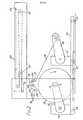
arrangement 1 for material (e.g. paper) on rolls. It consists of a splicing unit generally indicated at 10 and a series of mobile reel stands in the form ofroll transportation trolleys 11, 12 (although only two are shown, more may be provided). Each trolley consists of a base 13 with wheels orcastors 14 which supports roll-lifting and carryingarms 15. Thearms 15 of eachtrolley roll 16 of paper with its axis generally horizontal so that the web of paper may be drawn from the roll and supplied to thesplicing unit 10. Each trolley has means for controlling the unwinding of a roll in e.g. thearms 15 of thetrolley trolley trolleys splicing unit 10, so that as one roll is used up, another may be started. This idea of queued trolleys carrying paper rolls may be used with flying splicing arrangements, but zero-speed arrangements are preferred and the arrangement illustrated in Fig. 2 corresponds to the latter. - The trolleys serve for transport from the paper store to the machine and back, and as roll stands from which the paper is unwound. They can be queued so that they may be positioned sequentially adjacent the splicing unit, and moved so that as one roll finishes (on trolley 12) the next (on trolley 11) can be in position. The running web on the
trolley 12 is therefore positioned to pass over aroller 17 at thesplicing unit 10 at substantially the same angle, so that each subsequent splice is of a predetermined cut off length and is on the same side of the web. This reduces the amount of roll handling, enables the work at this part of the machine to be fitted in more flexibility with other machine operating tasks; and permits a machine layout with a better material flow, particularly in situations where part used or reject rolls are to be removed from the machine. - As shown in Fig. 2, a
paper web 18 from the leadingtrolley 12 passes via theroller 17 and apressure plate 19 to afestoon system 20. Thefestoon system 20 has aroller 21 which is movable between the position shown in solid lines and the position shown in dotted lines. Theroll 16 carrying thenext web 22 of paper to be used is mounted on thesecond trolley 11, and its leading end mounted on apivotable unit 23. Theprivotable unit 23 has apressure system 24 into which the leading ends of thepaper web 22 is fitted, preferably when theunit 23 is in its withdrawn position shown in dotted lines. - As the
first web 18 is run, theroller 21 is moved to the position shown in solid lines so that there is a significant amount of paper running within thefestoon unit 20. When the end of theweb 18 being withdrawn from thetrolley 12 approaches, or it is desired to replace one w0h with another, the input of theweb 18 to thefestoon unit 20 is stopped, but the output (in the direction of arrow 25) continues as theroller 21 moves towards its dotted position. With the part of theweb 18 adjacent thepressure plate 19 stationary, theunit 23 is swung through the position shown in solid lines until theattachment unit 24 comes in contact with the pressure plate, thereby pressing the end of the web 22 (on which adhesive is provided) onto theweb 18, causing a splice. Theweb 18 is then cut below thepressure plate 19 by aknife 26,unit 23 is then withdrawn, and theweb 22 may then be drawn into thefestoon unit 20 and theroller 21 moved back to its original position shown by a full line. - The accuracy of the feed of a
web splicing unit 10 and hence through thefestoon unit 20 to a printing machine depends on precise alignment of the axis of therolls 16. If the axis ofrolls 16 is not precisely positioned perpendicular to the direction ofarrows 25 of the output from thefestoon unit 20, there is the risk that theweb trolleys rolls 16, below the splicing unit. One such arrangement which may be used is shown in Figs. 3a and 3b. - There are two different alignments needed: to ensure that the axis of the rolls is precisely transverse to the direction of movement of the web, and to ensure that the axis of the roll is at the correct distance from the
splicer 10. Fig. 3a shows the first of these- As illustrated, one of thearms 15 ofa.trolley 11 has twoguide balls 30 rotatably mounted on its outer surface, and theother arm 15 has asingle guide ball 31, which is rotatably mounted, but also spring loaded, on its outer surface. When thetrolley 11 is passed below the splicer 10 (in Fig. 2) theballs guide rails 32, one on each side of the trolley. The twoballs 30 ensure that thecorresponding arm 15, and hence the rest of thetrolley 11, is precisely aligned with theguide rail 32, and the spring loadedball 31 ensures adjustment due to slight variations in the width of the trolley. The three-point contact of theballs - As was mentioned with reference to Fig. 2, the trolleys are mounted on wheels or
castors 14 and in theory, if thefloor 33 was prefectly flat, and the wheels were precisely made, this would ensure accurate vertical positioning of the axis of aroll 16. In practice, however, such accurate positioning is not possible, and therefore the Fig. 3b shows one way of achieving vertical positioning. Eachtrolley 11 has a pair ofsupport rollers 35 on each side thereof, and aramp 36 is positioned on thefloor 33 generally below thesplicer 10. As theleading wheel 14 of thetrolley 11 moves onto theramp 36, thesupport rollers 35 engage a pair ofguide rails 37, one on each side of thetrolley 21. The guide rails 37 slope upwardly in the direction of trolley movement, so as thetrolley 11 moves, the action of thesupport roller 35 and therail 37 is to lift the rear wheel orcastor 14 of thetrolley 11 clear of thefloor 33. Hence the vertical position of the trolley, and hence theroll 16, is determined primarily by theguide rail 37. - As the trolley moves.forwards, the
support roller 35 moves through positions A to J shown in Fig. 3b. - The system described above requires the
arms 15 of thetrolley 11 to be locked in position during the movement of the trolley'll below thesplicer 10. It is also thought possible to achieve accurate vertical positioning by moving thearms 15 to a position determined by a suitable stop, although such an arrangement is not preferred. - Thus, Figs. 3a and 3b illustrate one embodiment of the first aspect of the present invention, embodied as queuing trolleys for paper rolls.
- As explained with reference to Fig. 1, the paper web then passes to a printing unit 3. Fig. 4 illustrates an embodiment of such a unit 3, being a web-fed offset perfecting press according to the second aspect of the present invention. AS illustrated the press has three
cartridges blanket cylinders plate cylinders blanket cylinders 43,44: i.e. each cartridge contains a "printing couple". Normally the plate and blanket cylinders have the same diameter, but it is also known to have plate cylinders of half the circumference of the corresponding blanket cylinder. As illustrated, thecartridges cartridges cartridges web 2 passes round aroller 47 and between the pair ofblanket cylinders cartridge cartridges web 2 is carried on theplate cylinders - As shown in Fig. 4, a unit containing printing medium, e.g. an inking and dampening
train train - When printing is to occur, the inking and dampening
trains cartridges rollers 50 are brought into contact with theplate cylinders trains web 11, but are common to all threecartridges cartridge 41 is to print, thetrains rollers 50, move into contact with the twoplate cylinders cartridge 41. A printing run then occurs. At the end of that printing run, the inking and dampeningtrains trains 98,49 are moved vertically until they are adjacent one of the other twocartridges rollers 50 into contact with theplate cylinders cartridge - It is also possible for the cartridges to move vertically, with the trains remaining stationary, but this is mechanically more difficult to achieve. Note also that this arrangement permits "in machine" storage of the cartridges, which is more efficient than the known arrangc- ments.
- A suitable drive system for the press of Fig. 4 will now be described with reference to Figs. 5 and 6. As shown in the plan view of Fig. 5, the inking and dampening
trains support frame 51 movable relative to themain frame 52 of the press which supports thecylinders trains stop 53 may be provided on thesupport frame 51 to limit this horizontal movement. - The vertical movement of the
support frame 51, and hence of the inking and dampeningtrains motor 54 mounted on thesupport frame 51. Thatmotor 54 drives ashaft 55 extending across thesupport frame 51 and connected viabevel gears shafts pinion 60 engaging atoothed rack 61 on themain frame 52. Similarly,shaft 59 drives twopinions main frame 52 which engage correspondingtoothed racks 64,65 on the opposite side of themain frame 52. Thus rotation of themotor 54drives shafts pinions corresponding racks support frame 51 relative to themain frame 52. In this arrangement, a three-point mounting is used, but it would also be possible to provide a four or more point mounting by providing pinions additional on theshafts main frame 52. Accurate vertical positioning of the support frame may be achieved either by accurate control of themotor 54 or by providing a stop 66 (see Fig. 4) on themain frame 52. The stop 66 may be spring-loaded so that it moves out from themain frame 52 when thesupport frame 51 moves past it, and thesupport frame 51 then lowered onto the stop 66. Clearly the stop 66 has to be depressed to permit downward movement of thesupport frame 51, e.g. to operatecartridge 40 in Fig. 4. - The drive for the
cylinders cylinders cylinders cylinders - A
shaft 67 extends up themain frame 52 and movably on it, but engaged for rotation with it is agear 68 which meshes with acorresponding gear 69 connected to ashaft 70 which extends to aworm 71 which mates to aworm wheel 72. Ashaft 73 is secured to theworm wheel 72 and is supported on thesupport frame 51 by asupport 74. At the end ofshaft 73 remote from thecylinders air cylinder 75 which is capable of moving theshaft 73 axially. At the other end of theshaft 73 is aclutch plate 76 which engages a correspondingclutch plate 77 on astub shaft 78 extending from theplate cylinder 45. Theclutch plates shafts aperture 79 in themain frame 52. At the end of theplate cylinder 45 aie gears 80 which mesh withcorresponding gears 81 on theblanket cylinder 43. - Thus, when the
air cylinder 75 moves theshaft 73 so that theclutch plates shaft 67 is transmitted viagears shaft 70,worm 71,worm gear 72,shaft 73,clutch plates stub shaft 78 to the plate cylinder, and hence viagears - When the
air cylinder 75 moves theshaft 73 to disengage theclutch plates shaft 73 is sufficient to move theclutch plate 76 clear of theaperture 79, permitting the whole assembly on the support frame to be moved relative to themain frame 52 to another cartridge. This arrangement has the advantage that cylinders of cartridges not in use cannot have any drive thereto, and therefore can be handled safely, e.g. for replacement of the printing plates of those cylinders. Since the cylinder drive mechanism moves with the inking and dampening trains, it is impossible accidentally to drive cylinders which are not to print at any particular time. - The clutch formed by
clutch plates clutch plates corresponding plate cylinder 45 to the drive. Thus, irrespective of the initial position of theplate cylinder 45, its rotation will be synchronised with the rotation of theshaft 67. - Sometimes, however, it is desired to vary the synchronisation of the shaft G7 and the plate cylinder 4b, to advance or retard the printing image relative to the main drive. To do this, the
worm 71 is moved alongshaft 70 by alinear actuator 82, which normally holds theworm 71 fixed on theshaft 70. This rotates theworm wheel 72 which, viashaft 73, andclutch plates plate cylinder 45 relative to the position of thedrive shaft 67. The movement of theworm 71 may also be achieved using a motor or a hydraulic ram. Movement of theother plate cylinder 46 relative to theshaft 67 may be achieved in the same way either simultaneously with or separately from movement of theplate cylinder 45. - The drive to the inking and dampening
cylinders 50 of the inking and dampeningtrains cartridges motor 54 to move thesupport frame 51 relative to themain frame 52. - As can be seen from Fig. 6, gears 83 extend from the
shaft 70 fromgear 69 to theworm 71. These gears 83 engage on anepicyclic gearing 84 on afurther shaft 85. Each end of theshaft 85 carries gears 86 which engage gears 87 which connect to the drive system within the inking and dampening units in a conventional way. Thus theshaft 70 is connected toshaft 85 and the drive fromshaft 69 which drives thecylinders rollers 50. - However, this synchronisation depends on the diameter of the
plate cylinders units auxiliary drive motor 88 connected via theepicyclic gearing 84 to theshaft 85. The speed of rotation of thatauxiliary motor 88 is sensed, and the result fed to acomparator 89 which compares that speed with the speed of rotation of rollers 90 between which the paper web passes. These rollers 90 may also be associated with epicyclic gearing. If it is found that the drive is not synchronised, then themotor 88 is speeded up or slowed down until synchronisation is achieved. Thus the drive to themotor 88 modifies the drive transmitted by thegearing 83 to theshaft 85. - Fig. 6 illustrates a further feature of the system, namely that the
shaft 67 which drives the plate and blanket cylinder is driven from a shaft 91 which extends beyond the printing station. Thus, additional printing stations may be connected to the shaft or, as illustrated in Fig. 6, may be connected to the perforating tool oi a pre-folder 92, or the perforator and cutter of a cutting station. These will be described in detail later, but as can be seen the maim shaft 91 hasgears 93 driving ashaft 94 of the pre-folder 92 which rotates a perforatingtool 95. Again,epicyclic gearing 96 may be provided, linked to thecomparator 89. - As illustrated in Fig. 4, one pair of inking and dampening
trains cartridges 100, 101,102,103, each of which is similar to thecartridges web 2 of paper passes up the middle of the-cartridges 100,101, 102,103. Four inking and dampening trains are provided, an upper pair 104,105 serving the upper two cartridges 100,101 and a lower pair 106,107 serving the lower two cartridges 102,103. In this way, for example, it is possible to print two different colours in like size print cylinders, and yet still maintain the possibility of change of image and/or repeat length. Also, as shown in Fig. 7, the cylinders of the cartridges may be different sizes, e.g. with the cylinders of cartridges 100,102 being smaller than the cylinders of cartridges 101,103. The press shown in Fig. 7, apart from having four cartridges, as discussed above, may be generally similar to the press of Fig. 4, and have a drive similar to that described with reference to Figs. 5 and 6. Therefore, further detailed description of the arrangement of Fig. 7 will be omitted. - One feature of this system is that by adding additional cartridges, and possibly additional inking and dampening
trains - The embodiment described above with reference to Figs. 4 to 7 have the inking and dampening units moving vertically relative to a vertically stacked array of cartridges. It is also possible to have a horizontal arrangement in which cartridges are in a fixed horizontal array and the inking and dampening units are movable relative to the cartridges on which printing is to commence. One or two inking and dampening units may.be used. The drive to the plate cylinders and the inking and dampening units is as described in the vertical unit shown in Fig. 5. The difference lies in the fact that a horizontal power shaft running parallel to the main power shaft may be used to drive the plate cylinders. The drive from the main power shaft may be provided by a vertical shaft connecting the power shaft to the horizontal shaft through two pairs of bevel gears.
- As described above, the array of cartridges is fixed and the inking and dampening units are movable. Since the present invention depends on relative movement, it js also possible to have the inking dampening units fixed and move the cartridges of the array. The cartridges may be moved by many ways, such as rollers, guide rails, or pneumatic jacks,. and the drive to the plate cylinders of the cartridges may be achieved by single toothed clutches as described with reference to Fig. 6. The advantage of an arrangement using movable cartridges is that the inking and dampening units are fixed and hence the drive to the system may be fixed. However, it is currently considered to be more difficult to move the cartridges than to move the inking and dampening units.
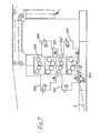
- A further embodiment involving fixed inking and dampening units and movable cartridges is shown in Figs. 8 and 9. This embodiment has four cartridges 111,112,113,114 such as to form a
carousel 115. As illustrated in Fig. 8, each cartridge has a pair ofplate cylinders 116 and a pair ofblanket cylinders 117 in a manner generally similar to the plate and blanket cylinders of thecartridges - A
web 2 of paper enters the printing machine via rollers 118,119 to move along a horizontal path through two 114,112 of the four cartridges 111,112,113,114 of thecarousel 115. The carousel is rotatably supported on aframe 120 and asecond frame 121 supports one or two inking and dampening units 122 (one inking and dampening unit is shown more clearly in Fig. 9). Where one inking and dampening unit is provided it is preferably on the side of thecarousel 115 into which the web is fed. Where two inking and dampening units are provided they are normally on opposite sides of thecarousel 115 to permit the cartridges 111,113 or the cartridges 112,114 to be driven. - The printing machine shown in Figs. 8 and 9 may operate in one of several ways. For example, it is possible to carry out a print run using
only cartridge 114, and during that print run,cartridge 112 may be prepared for a different print run. When the print run throughcartridge 114 is completed, theblanket cylinders 117 ofcartridge 114, may be withdrawn from theweb 2, and the drive to that cartridge removed and- then theblanket cylinders 117 ofcartridge 112 moved into contact with the web and a drive applied tocartridge 112. A print run may then be carried out usingcartridge 112 andcartridge 114 prepared. Ifcartridges cartridges - To change printing to cartridges 111,113, a
motor 123 drives thecarousel 115 and turns it on itsframe 120, through 90" so that thecartridges 111, 113are aligned with theweb 2. Accurate positioning of the carousel may be achieved by steps (not shown). This rotation of thecarousel 115 means that theweb 2 must be broken in order to change from one pair of cartridges to the other, and hence this embodiment is less advantageous than the embodiment of Fig. 4. As shown byarrow 124, thecarousel 115 may be rotated clockwise or anticlockwise, as desired. - The drive arrangement for the embodiment of Figs. 8 and 9 will now be described. Referring particularly to Fig. 9, a shaft 125 (which may be connected to a drive system for an entire printing system as discussed with refernce to Fig. 6) drives via gears 126 a
shaft 127, and hence viagears 128 to adrive arrangement 129 for the inking and dampeningunit 122. Thedrive arrangement 129 may be similar to that described with reference to Fig. 6, i.e. the drive may pass viaepicyclic gearing 130 which may be acted on by anauxiliary motor 131 enabling the synchronisation of the drive. - The
shaft 127 also has afurther gear 132 which connects to aworm 133 acting on aworm wheel 134. The worm wheel turns ashaft 135, at one end of which is alinear actuator 136 and at the other end of which is a clutch 137. The clutch 137 connects to ashaft 138 which drives aplate cylinder 116 of one of the cartridges 111,112,113,114. Thus the drive to the cartridge of this embodiment is generally similar to that described with reference to Fig. 5, and its operation will therefore be immediately apparent. - As shown schematically on the right hand side of Fig. 9, the
shaft 127 may also extend to the opposite edge of thecarousel 115, to drive another inking and dampening unit (not shown). - A further development of the arrangement shown in Fig. 4 (or Figs. 7 or 8 and 9) is concerned with the mounting of the cylinders within the
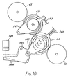
cartridges - One embodiment of the system for moving the
blanket cylinders blanket cylinder 44 is pressed into contact with its associatedplate cylinder 46, with thegears blanket cylinders blanket cylinder 43 then bears against itsplate cylinder 45. Normally, a slight freedom is provided in the mounting of theblanket cylinders blanket cylinder 44 is pressed into contact with its adjacent cylinders, both cylinders will automatically position themselves into their precise printing positions by the reactions of the contact pressures to their associated plate cylinders and their co-acting blanket cylinder. - To engage the
blanket cylinders cylinder 44 in Fig. 10) is movable so that its axis moves between positions B and A. This may be achieved, e.g. by mounting the end so the support on which the cylinder rests in a slot, with one end of the slot corresponding to cylinder axis in position B and the other formed in such a way as to allow the cylinder axis to have freedom from the slot sides when in position A. The cylinder axis is pressed into position B by a loadedplunger 140 when printing is not taking place, so thatblanket cylinder 44 is in the position shown in dotted lines, and is also out of contact with itscorresponding plate cylinder 46 and theother blanket cylinder 43. - The
other blanket cylinder 43 is carried on a pivotedsupport 141 which allows the cylinder axis to move along a restricted arc within an oversize hole (not shown). The boundary of this hole does not influence the axis position when theblanket cylinder 43 is in contact withplate cylinder 45 but does restrict the amount of movement away from that plate cylinder. This permits a gap to open betweenblanket cylinder 43 andplate cylinder 45 asblanket cylinder 44 moves to position B and also a gap betweenblanket cylinder cylinder 43 being able to followcylinder 44 but not far enough to maintain contact with it. A similar effect can also be achieved by mounting the support of theblanket cylinder 43 in a slot arranged to allow contact withplate cylinder 45 but restrict movement away from it. If nothing holds thecylinder 43 in contact withplate cylinder 45 it moves away on its pivotedsupport 141 under a separating force which may be provided by gravity. It is required that the separating force should not exceed a threshold value. If the gravitational (or other) force on theroll 43 exceeds this value, the separating force is reduced by means of aspring 142 or other biasing means such as an air cylinder acting on the pivotedsupport 141. - As shown in Fig. 10, the
blanket cylinder 44 is also mounted on abracket 143 which is connected to alever 144 pivoting atpoint 145. Whenlever 144 is moved, e.g. by apneumatic system 146, to the position shown in solid lines, a force is applied toblanket cylinder 44 which moves its axis against the pressure ofplunger 140 away from position B towards position A (i.e. the printing position). Theblanket cylinder 44 abuts itsplate cylinder 46, and also contacts theother blanket cylinder 43, moving it to contact theother plate cylinder 45.. The precise positioning and pressure achieved is finally determined by the reactions of the blanket cylinders to their adjacent cylinders and the controlled forces moving them into position (and no longer by the influence of their mounting slots or holes). - Thus, by providing means for moving one of the cylinders into and out of a printing position, and means for the other cylinder to follow over a restricted distance controlled by force reactions, at the "on" position and slot or hole limits at the "off" position, printing may be disengaged and re-engaged quickly and simply, even after a different cartridge has been installed in the press. That is to say, the system provides force loading and self- setting. Ideally the cylinder should run on a continuous surface, and this is best achieved by cylinder bearers (to be discussed later).
- The printing machines discussed with reference to Figs. 4 to 10 thus generally permit printing to occur continously, but also permit changes of cartridges to be made with quick and easy establishment of the precise settings required. This is very important in minimising down-time. The arrangement shown in Fig. 4 is particularly applicable to single colour (including black) printing. It is also applicable to colour printing although then difficulties may occur in having common inking and dampening trains, and a large number of cartridges and inking and dampening trains may become necessary.
- Figs. 11 and 12 illustrate a design of cylinder which is particularly useful in the present invention. Each cylinder has a
core 150 of a given size to which rim units of differing thicknesses may be fitted, as desired. Fig. 11 shows a cylinder with a relativelythick rim unit 151 and Fig. 12 shows a cylinder with a relativelythin rim unit 152. By interchanging the rim units the effective diameter of the cylinder can be changed, without removing the core 150 from the press. The rim units 151,152 are anti-corrosive (acid gum in the damping fluid may otherwise cause corrosion) and removal of the rim units also allows easy maintenance. - As shown in Figs. 11 and 12, the rim unit 151,152 supports a
printing plate 153, connected to it by clips 154,155 which enable theprinting plate 153 to be stretched around the cylinder. Figs. 11 and 12 also show the end rings 156 and clamps 157 at the end of the cylinder for holding the rim unit 151,152 onto thecore 150. Therings 156 act as bearers to ensure smooth rotation of the cylinders, as has been mentioned previously. Note that therings 156 are slightly thicker than the rim units 151,152, so thai their radially outer surface corresponds exactly with the outer surface of theprinting plate 153. - Once the paper web has been printed, then another aspect of the invention comes into play. In most cases, the possibilities for folding of paper whilst in web form are limited (although one or more longitudinal folds may be made as will be described later), but few complicated folding combinations are practicable with the output from web printing machines. On the other hand, there are various techniques for folding paper sheets in e.g. gate folds, multiple transverse folds and longitudinal folds; two are ilustrated in Figs. 13 and 14.
- Fig. 13 shows an arrangement known as a knife folder in which the
paper sheet 160 passes over a pair of contra-rotating rollers 161,162. With thesheet 160 stationary in that position, aknife 163 is lowered, forcing thesheet 160 into the "nip" 164, thereby providing a firm fold. Thesheet 160 is then drawn down between the rollers 161,162 for subsequent use. Theknife 163 will normally be connected to a photocell or similar detector which detects the presence ofsheet 160 below the knife. In this way the folding operation can by synchronised with the arrival of thepaper sheet 160 at the folder, rather than synchronised with e.g. an earlier stage of the printing operation. - Fig. 14 shows an arrangement known as a buckle folder in which a sheet of
paper 170 passes between a first pair of contra-rotating rollers 171,172 and its leading edge strikes aramp 173. The action of the rollers 171,172 forces thepaper sheet 170 up theramp 173, until its leading edge strikes astop 174, the position of which is determined by the desired position of the fold. When paper strikes thestop 174, it can no longer move up the ramp, and so the action of rollers 171,172 is force thepaper sheet 170 into the nip defined betweenroller 172 and anotherroller 175. This forms a sharp fold in the paper, which then passes downwardly due to the action ofrollers ramp 176 and move downwardly to another stop 177. In this position thesheet 170 is then acted on byrollers rollers 179. Thus, the system in Fig. 14 permits successive transverse folding and perforating of the sheet, and by providing several such units with one or two ramps, any number of transverse folds may be provided. If the direction of movement of the sheet is changed between one buckle folder and the next, both longitudinal and transverse folds may be provided. However, the first fold is generally a transverse one, or extra equipment would be needed. Again the folding of thesheet 170 is in timed dependence on its arrival at the folder, not in dependence of the timing of the printing - operation.
- It is also possible to provide folders which are a combination of knife and buckle folders.
- Referring now to Figs. 15 and 16, a
paper web 2 from a web printing machine (e.g. as in Fig. 4) is cut into sheets by aknife arrangement 180. Fig. 15 shows a perspective view of the arrangement, and theweb 2 from the printing machine is first turned through 90° by a bar 6 as has already been described with reference to Fig. 1. Of course, this is not essential and the web path to theknife arrangement 180 may be straight as shown by dotted lines in Fig. 15. Thisknife unit 180 may be powered from a drive shaft common with the printing station, as described with reference to Fig. 6, i.e. theknife unit 180 shown in Figs. 15 and 16 corresponding to the element 91 in Fig. 6. A drier unit may also be provided as discussed with reference to Fig. 1. Once theknife arrangement 180 has cut theweb 2 into sheets, they may be passed to afolder 181 which may be e.g. e buckle folder such as shown in Fig. 14, although a knife folder as shown in Fig. 13 may also be used. One factor to bear in mind is that the speed of the web from the printing machine may be faster than can be handled by the known sheet folding systems, and it may be necessary to divide the sheet flow so that sub-streams follow two or more routes. In this example adivider 183 is provided so that some sheets pass straight on to thefolder 181, and others are diverted to anotherfolder 182. Further changes in direction may occur atunits - Whereas, as explained'above, the first fold is generally a transverse fold in sheet fed systems. Fig. 16 shows a simple way of providing a first, longitudinal, fold in the paper. This is particularly important with thin paper which cannot easily be handled by buckle folders such as shown in Fig. 14. The
paper web 2 from the printer machine and (possibly) the drier passes to a former 190 which is triangularly shaped so that a longitudinal fold is placed in the paper as it moves downwardly from a roller 191 to a pair ofguide rollers 192, between which a throat is formed. Thus, the paper fed to a buckle folder generally indicated at 193 has already been folded once, in the longitudinal direction, and is therefore less subject to malfunctioning in the folder. Again, however, a knife orsimilar cutter 194 has to be provided before the web enters thebuckle folder 193. - As described above, the folds are made directly to the paper. However, to ease the transverse folding, a
transverse perforating unit 195 may be provided upstream of the knife orother cutter 194. Furthermore, the use of a web printer permits longitudinal perforation to facilitate the longitudinal folding shown in Fig. 16, by means of thecontinuous perforating wheel 190 producingperforations 197. Furthermore, thiswheel 196 may be powered from the main drive shaft to the printing station, as was described with reference to Fig. 6. Likewise, any other longitudinal fold can be produced on a continuous basis. Perforation also assists quality by permitting air to escape from within the fold.
Claims (46)
characterised in that:
characterised in that:
characterised in that:
characterised in that:
Priority Applications (4)
| Application Number | Priority Date | Filing Date | Title |
|---|---|---|---|
| EP90120465A EP0420297B1 (en) | 1986-05-14 | 1987-05-13 | Processing paper and other webs |
| AT87304243T ATE79807T1 (en) | 1986-05-14 | 1987-05-13 | PROCESSING OF PAPER AND OTHER WEBS. |
| EP91201802A EP0459595B1 (en) | 1986-05-14 | 1987-05-13 | Processing paper and other webs |
| EP91201801A EP0459594B1 (en) | 1986-05-14 | 1987-05-13 | Processing paper and other webs |
Applications Claiming Priority (2)
| Application Number | Priority Date | Filing Date | Title |
|---|---|---|---|
| GB868611722A GB8611722D0 (en) | 1986-05-14 | 1986-05-14 | Processing paper & other webs |
| GB8611722 | 1986-05-14 |
Related Child Applications (4)
| Application Number | Title | Priority Date | Filing Date |
|---|---|---|---|
| EP90120466.9 Division-Into | 1990-10-25 | ||
| EP90120467.7 Division-Into | 1990-10-25 | ||
| EP90120465.1 Division-Into | 1990-10-25 | ||
| EP91201801.7 Division-Into | 1991-07-11 |
Publications (3)
| Publication Number | Publication Date |
|---|---|
| EP0246081A2 true EP0246081A2 (en) | 1987-11-19 |
| EP0246081A3 EP0246081A3 (en) | 1988-03-30 |
| EP0246081B1 EP0246081B1 (en) | 1992-08-26 |
Family
ID=10597841
Family Applications (6)
| Application Number | Title | Priority Date | Filing Date |
|---|---|---|---|
| EP91201802A Expired - Lifetime EP0459595B1 (en) | 1986-05-14 | 1987-05-13 | Processing paper and other webs |
| EP90120467A Withdrawn EP0420299A1 (en) | 1986-05-14 | 1987-05-13 | Processing paper and other webs |
| EP90120465A Expired - Lifetime EP0420297B1 (en) | 1986-05-14 | 1987-05-13 | Processing paper and other webs |
| EP91201801A Expired - Lifetime EP0459594B1 (en) | 1986-05-14 | 1987-05-13 | Processing paper and other webs |
| EP90120466A Withdrawn EP0420298A1 (en) | 1986-05-14 | 1987-05-13 | Processing paper and other webs |
| EP87304243A Expired - Lifetime EP0246081B1 (en) | 1986-05-14 | 1987-05-13 | Processing paper and other webs |
Family Applications Before (5)
| Application Number | Title | Priority Date | Filing Date |
|---|---|---|---|
| EP91201802A Expired - Lifetime EP0459595B1 (en) | 1986-05-14 | 1987-05-13 | Processing paper and other webs |
| EP90120467A Withdrawn EP0420299A1 (en) | 1986-05-14 | 1987-05-13 | Processing paper and other webs |
| EP90120465A Expired - Lifetime EP0420297B1 (en) | 1986-05-14 | 1987-05-13 | Processing paper and other webs |
| EP91201801A Expired - Lifetime EP0459594B1 (en) | 1986-05-14 | 1987-05-13 | Processing paper and other webs |
| EP90120466A Withdrawn EP0420298A1 (en) | 1986-05-14 | 1987-05-13 | Processing paper and other webs |
Country Status (19)
| Country | Link |
|---|---|
| US (2) | US4831926A (en) |
| EP (6) | EP0459595B1 (en) |
| JP (4) | JP2545389B2 (en) |
| KR (1) | KR960003346B1 (en) |
| CN (2) | CN1045078A (en) |
| AT (4) | ATE119474T1 (en) |
| AU (3) | AU611388B2 (en) |
| BR (1) | BR8702455A (en) |
| CA (1) | CA1296945C (en) |
| CZ (1) | CZ284471B6 (en) |
| DD (5) | DD273806A5 (en) |
| DE (6) | DE3750405T2 (en) |
| ES (4) | ES2072529T3 (en) |
| GB (7) | GB8611722D0 (en) |
| HK (1) | HK65592A (en) |
| IE (1) | IE59792B1 (en) |
| IN (3) | IN169606B (en) |
| RU (4) | RU2066277C1 (en) |
| SG (1) | SG74192G (en) |
Cited By (10)
| Publication number | Priority date | Publication date | Assignee | Title |
|---|---|---|---|---|
| FR2723882A1 (en) * | 1994-08-24 | 1996-03-01 | Frankenthal Ag Albert | ROTARY PRINTING MACHINE WITH ROLLS IN POLYCHROMY, FOR PRINTING CITY WORKS |
| EP0638419B1 (en) * | 1993-08-13 | 1999-05-06 | Maschinenfabrik Wifag | Supporting framework for a rotary web printing press |
| DE19860928C1 (en) * | 1998-12-30 | 2000-06-21 | Koenig & Bauer Ag | Printing unit with common printing module made from four cylinders, takes up little room |
| WO2005097503A2 (en) | 2004-04-05 | 2005-10-20 | Koenig & Bauer Aktiengesellschaft | Drives for a printing unit |
| WO2005097504A2 (en) | 2004-04-05 | 2005-10-20 | Koenig & Bauer Aktiengesellschaft | Devices for mounting of a cylinder printing press and method for adjustment of a print on-position |
| WO2005097505A2 (en) | 2004-04-05 | 2005-10-20 | Koenig & Bauer Aktiengesellschaft | Printing unit on a web-fed rotary printing press |
| DE10302214B4 (en) * | 2003-01-22 | 2006-04-20 | Koenig & Bauer Ag | Rack for a printing press |
| EP1894719A2 (en) | 2004-04-05 | 2008-03-05 | Koenig & Bauer Aktiengesellschaft | Printing unit on a web-fed rotary printing press |
| US8069785B2 (en) | 2006-03-03 | 2011-12-06 | Koenig & Bauer Aktiengesellschaft | Printing groups of a printing press |
| US8069786B2 (en) | 2005-04-21 | 2011-12-06 | Koenig & Bauer Aktiengesellschaft | Printing groups comprising at least two cooperating cylinders and radially movable bearing units |
Families Citing this family (68)
| Publication number | Priority date | Publication date | Assignee | Title |
|---|---|---|---|---|
| DE3702327C2 (en) * | 1987-01-27 | 1998-01-15 | Koenig & Bauer Albert Ag | Web rotary printing machine |
| FR2633871B1 (en) * | 1988-07-07 | 1991-05-17 | Sarda Jean | MULTI-COLORED OFFSET PRINTS, VARIABLE FORMAT, FOR PRINTING CONTINUOUS TAPES |
| CA2025552C (en) * | 1989-09-20 | 1993-12-21 | Kunio Suzuki | Paper web threading apparatus for rotary printing press |
| JPH0688696B2 (en) * | 1990-08-28 | 1994-11-09 | 株式会社東京機械製作所 | Paper threading device for web material processing machine |
| DE4112925A1 (en) * | 1991-04-19 | 1992-10-22 | Frankenthal Ag Albert | PRINTING UNIT FOR A ROTATIONAL PRINTING MACHINE |
| US5203761A (en) * | 1991-06-17 | 1993-04-20 | Sealed Air Corporation | Apparatus for fabricating dunnage material from continuous web material |
| JPH05131608A (en) * | 1991-11-14 | 1993-05-28 | Tokyo Kikai Seisakusho Ltd | Multi-color printing machine |
| JP2952440B2 (en) * | 1991-11-15 | 1999-09-27 | 株式会社 東京機械製作所 | Multicolor printing press |
| IT1253922B (en) * | 1991-12-20 | 1995-08-31 | Gd Spa | TROLLEY FOR LOADING REELS INTO A FEEDING DEVICE OF A PACKAGING MACHINE |
| JPH0749347B2 (en) * | 1991-12-26 | 1995-05-31 | 株式会社東京機械製作所 | Web stock paper width adjusting device, web stock paper width adjusting method, and planographic rotary printing machine having web stock paper width adjusting device |
| JP2889057B2 (en) * | 1992-07-28 | 1999-05-10 | 株式会社東京機械製作所 | Web paper width adjusting device, web paper width adjusting method, and lithographic rotary printing press having web paper width adjusting device |
| US5351616A (en) * | 1992-08-13 | 1994-10-04 | Man Roland Druckmaschinen Ag | Rotary web printing machine, particularly for printing on thick or carton-type stock webs with replaceable plate cylinders |
| US5289769A (en) * | 1992-08-17 | 1994-03-01 | W. O. Hickok Mfg., Co. | Method and apparatus for changing a printing sleeve |
| DE4228610B4 (en) * | 1992-08-28 | 2004-07-29 | Koenig & Bauer Ag | Paper guide for web-fed rotary printing machines |
| JPH08454B2 (en) | 1992-10-23 | 1996-01-10 | 株式会社東京機械製作所 | Web material width adjusting method, width adjusting device, and planographic rotary printing machine having the width adjusting device |
| US5301609A (en) * | 1993-03-04 | 1994-04-12 | Heidelberg Harris Inc. | Printing unit with skew and throw-off mechanisms |
| JP2968905B2 (en) * | 1993-03-19 | 1999-11-02 | 株式会社 東京機械製作所 | Web paper width adjusting device |
| US5540149A (en) * | 1993-10-26 | 1996-07-30 | Magnum Manufacturing Limited | Rotary printing machines |
| JP3300137B2 (en) * | 1993-11-18 | 2002-07-08 | 理想科学工業株式会社 | Plate cylinder rotary drive and support device for multi-plate cylinder stencil printing machine and multi-plate cylinder stencil printing machine |
| US5370047A (en) * | 1993-12-01 | 1994-12-06 | Paper Converting Machine Company | Flexographic press adapted for short runs and method |
| DE4408026A1 (en) * | 1994-03-10 | 1995-09-14 | Koenig & Bauer Ag | Printing unit for a multi-color web-fed rotary printing machine |
| DE4408027A1 (en) * | 1994-03-10 | 1995-09-14 | Koenig & Bauer Ag | Multi-color web-fed rotary printing machine for commercial printing |
| DE4408025A1 (en) * | 1994-03-10 | 1995-09-14 | Koenig & Bauer Ag | Printing unit for a multi-color web-fed rotary printing machine |
| EP0687559A1 (en) * | 1994-06-15 | 1995-12-20 | Ferd. Rüesch AG. | Installation with printing units arranged in series |
| DK0719720T3 (en) * | 1994-12-30 | 1998-04-27 | Ferag Ag | Storage device for a roller unit and device for processing printing products |
| DE19516445A1 (en) * | 1995-05-04 | 1996-11-07 | Wifag Maschf | Rotary printing machine with a free-standing folder |
| DE19516653C1 (en) * | 1995-05-05 | 1996-09-19 | Wifag Maschf | Rotary printing machine with swiveling rubber cylinders |
| JP3246557B2 (en) * | 1996-10-25 | 2002-01-15 | ケーニツヒ ウント バウエル アクチエンゲゼルシヤフト | Apparatus for correcting fan-out effects in web rotary printing presses |
| DE59802993D1 (en) * | 1997-03-04 | 2002-03-21 | Roland Man Druckmasch | Offset printing machine for fast production changes |
| US5868071A (en) * | 1997-09-02 | 1999-02-09 | Goss Graphic Systems, Inc. | Variable cutoff printing press |
| DE19805898C2 (en) * | 1998-02-13 | 2003-09-18 | Roland Man Druckmasch | Printing unit for a web-fed rotary printing machine |
| US6186064B1 (en) * | 1998-05-22 | 2001-02-13 | Heidelberger Druckmaschinen Ag | Web fed rotary printing press with movable printing units |
| US6227111B1 (en) * | 1998-10-21 | 2001-05-08 | Heidelberger Druckmaschinen Ag | Impression setting mechanism for a printing unit |
| US6705499B1 (en) * | 1999-03-19 | 2004-03-16 | Koenig & Bauer Aktiengesellschaft | Rollers for guiding paper webs |
| RU2152903C1 (en) * | 1999-09-17 | 2000-07-20 | Исангулов Кашфиль Исмагилович | Method of preparing dispersed modified silica |
| JP2001310440A (en) * | 2000-04-27 | 2001-11-06 | Miyakoshi Printing Machinery Co Ltd | Tower-type offset rotary press |
| JP2002046251A (en) | 2000-06-26 | 2002-02-12 | Heidelberger Druckmas Ag | Mechanism for drawing out cylinder using eccentric box |
| US6840616B2 (en) * | 2001-03-29 | 2005-01-11 | Scott Summers | Air folder adjuster apparatus and method |
| DE10150081B4 (en) * | 2001-10-10 | 2005-12-15 | Koenig & Bauer Ag | Rotary press |
| DE10248249B4 (en) * | 2002-10-16 | 2006-06-01 | Koenig & Bauer Ag | Dryer for a material web |
| DE10257282A1 (en) * | 2002-12-07 | 2004-06-24 | Koenig & Bauer Ag | Process for the flying change of printing plates in sheet-fed offset rotary printing machines |
| DE10260574A1 (en) * | 2002-12-21 | 2004-07-01 | Man Roland Druckmaschinen Ag | Modular printing unit |
| US20060150838A1 (en) * | 2003-07-08 | 2006-07-13 | Goss Graphic Systems Limited | Printing press |
| DE102004015248A1 (en) * | 2004-03-29 | 2005-10-13 | Goss International Montataire S.A. | Lifting sleeve for a printing cylinder of an offset printing machine |
| JP4445317B2 (en) * | 2004-04-16 | 2010-04-07 | 西研グラフィックス株式会社 | Towing traveling body for automatic paper threading device |
| DE102005002847A1 (en) * | 2005-01-20 | 2006-07-27 | Man Roland Druckmaschinen Ag | Rotary press |
| CN101208201B (en) * | 2005-03-30 | 2011-10-05 | 高斯国际美洲公司 | Web offset printing press with autoplating |
| US7775159B2 (en) | 2005-03-30 | 2010-08-17 | Goss International Americas, Inc. | Cantilevered blanket cylinder lifting mechanism |
| JP4814309B2 (en) | 2005-03-30 | 2011-11-16 | ゴス インターナショナル アメリカス インコーポレイテッド | Printing unit having blanket cylinder support surface |
| WO2006104830A2 (en) | 2005-03-30 | 2006-10-05 | Goss International Americas, Inc. | Web offset printing press with articulated tucker |
| JP4829291B2 (en) * | 2005-04-11 | 2011-12-07 | ゴス インターナショナル アメリカス インコーポレイテッド | Printing unit that enables automatic plating using a single motor drive |
| AR051361A1 (en) * | 2005-07-06 | 2007-01-10 | Badran Santiago Pedro | A MACHINE FOR LITOGRAPHIC PRINTING OF HOJALATA |
| DE102005042351A1 (en) * | 2005-09-07 | 2007-05-03 | Man Roland Druckmaschinen Ag | Device for processing web-shaped material |
| EP1834779A1 (en) * | 2006-03-14 | 2007-09-19 | Kba-Giori S.A. | Inspection system for a sheet-fed recto-verso printing press |
| US7532309B2 (en) | 2006-06-06 | 2009-05-12 | Nikon Corporation | Immersion lithography system and method having an immersion fluid containment plate for submerging the substrate to be imaged in immersion fluid |
| US8157141B2 (en) * | 2006-06-14 | 2012-04-17 | Cryovac, Inc. | System and method for detecting and registering serrated bags |
| GB2444563B (en) * | 2007-03-15 | 2009-04-22 | M & A Thomson Litho Ltd | Printing apparatus |
| DE102007019864B4 (en) * | 2007-04-23 | 2011-06-22 | KOENIG & BAUER Aktiengesellschaft, 97080 | Longitudinal perforating devices for a web-fed rotary printing machine with at least one perforating blade |
| DE102007000928B4 (en) * | 2007-08-31 | 2012-06-06 | Koenig & Bauer Aktiengesellschaft | Rotary press |
| FI120729B (en) * | 2008-07-31 | 2010-02-15 | Metso Paper Inc | Fiber web production line and method |
| ITFI20120213A1 (en) * | 2012-10-17 | 2014-04-18 | Futura Spa | ELEMENT FOR THE TRAFFIC TRANSFORMATION MATERIALS. |
| JP6383286B2 (en) * | 2014-12-24 | 2018-08-29 | 株式会社小森コーポレーション | Electronic circuit printing method and apparatus |
| CN108002134B (en) * | 2017-06-21 | 2019-09-24 | 扬州市青山环保科技有限公司 | A kind of weaving bobbin winder device |
| DE102018215893A1 (en) * | 2017-10-17 | 2019-04-18 | Heidelberger Druckmaschinen Ag | Folding machine with at least two folders and a delivery |
| JP7270128B2 (en) * | 2019-02-13 | 2023-05-10 | ケイディケイ株式会社 | Continuous paper folding means |
| US12612277B2 (en) | 2021-06-22 | 2026-04-28 | Hewlett-Packard Development Company, L.P. | Printing to substrates |
| CN116573459B (en) * | 2023-04-03 | 2026-02-03 | 彩虹(合肥)液晶玻璃有限公司 | Paper running mechanism for glass substrate semi-finished product system |
| DE102023109491A1 (en) * | 2023-04-14 | 2024-10-17 | Manroland Goss Web Systems Gmbh | Printing machine and method for producing variable sheet lengths |
Family Cites Families (74)
| Publication number | Priority date | Publication date | Assignee | Title |
|---|---|---|---|---|
| DE652089C (en) * | 1937-10-25 | Fallert & Co A G | Circular knife for longitudinal cutting of lengths of paper in front of the folding former of a rotary printing machine | |
| US10330A (en) * | 1853-12-20 | Attaching hooks and eyes to cards | ||
| US1160444A (en) * | 1915-07-14 | 1915-11-16 | Linotype Machinery Ltd | Apparatus for printing late news in web-printing presses or for other purposes. |
| US2077403A (en) * | 1930-10-09 | 1937-04-20 | Eiseman Maurice | Printing press for newspaper work |
| US1963042A (en) * | 1931-11-11 | 1934-06-12 | Union Bag & Paper Corp | Inking mechanism for printing machines |
| US2146586A (en) * | 1937-06-04 | 1939-02-07 | Meisel Press Mfg Company | Printing press |
| US2149028A (en) * | 1937-07-02 | 1939-02-28 | Meisel Press Mfg Company | Convertible printing press |
| US2172361A (en) * | 1937-11-27 | 1939-09-12 | Hoe & Co R | Folding mechanism for printing machines |
| US2216562A (en) * | 1939-10-26 | 1940-10-01 | Cottrell C B & Sons Co | Rotary web printing press |
| CH384521A (en) * | 1961-04-10 | 1964-11-30 | Vigano Vittorio | Trolley for transporting fabric wound on a roller from one point to another in the processing cycle |
| DE1436541A1 (en) * | 1964-04-02 | 1969-02-06 | Roland Offsetmaschf | Web-fed rotary printing press |
| US3323452A (en) * | 1965-01-15 | 1967-06-06 | Miehle Goss Dexter Inc | Variable cut-off web offset press |
| GB1082033A (en) * | 1965-04-12 | 1967-09-06 | Kleinewefers Soehne J | Winding-off apparatus for material lengths wound on reels, especially paper reels |
| GB1245204A (en) * | 1969-03-29 | 1971-09-08 | Johann Heinrich Saueressig | Colour intaglio printing machine, more particularly for printing textiles |
| US3604350A (en) * | 1969-04-23 | 1971-09-14 | Lee Machinery Corp | Flexographic presses with interrupter and cylinder register mechanisms |
| US3601049A (en) * | 1969-05-21 | 1971-08-24 | Olivetti & Co Spa | Ink train cartridge |
| GB1313855A (en) * | 1969-07-05 | 1973-04-18 | Masson Scott Thrissell Eng Ltd | Means for unwinding reels of sheet material |
| US3859883A (en) * | 1970-02-16 | 1975-01-14 | Butler Automatic Inc | Web supply apparatus |
| AT308785B (en) * | 1970-02-25 | 1973-06-15 | De La Rue Giori Sa | MULTICOLOR STEEL STITCH PRINT MACHINE |
| CH502897A (en) * | 1970-05-26 | 1971-02-15 | De La Rue Giori Sa | Multi-color offset rotary printing machine |
| DE2033836C3 (en) * | 1970-07-08 | 1980-07-10 | Walter Dr. 6100 Darmstadt Matuschke | Web-fed rotary printing press |
| US3718299A (en) * | 1971-11-22 | 1973-02-27 | Harris Intertype Corp | Roll out stand |
| NL7117191A (en) * | 1971-12-15 | 1973-06-19 | ||
| DE2234089C3 (en) * | 1972-07-08 | 1975-01-23 | Automatic Druckmaschinenfabrik Dr. W. Hinniger U. Soehne, 1000 Berlin | Offset web-fed rotary printing press |
| US3793952A (en) * | 1972-07-25 | 1974-02-26 | Windmoeller & Hoelscher | Convertible printing mechanism for intaglio and flexographic printing |
| US3858819A (en) * | 1972-10-24 | 1975-01-07 | Butler Automatic Inc | Web supply apparatus |
| IE39031B1 (en) * | 1972-12-21 | 1978-07-19 | Saueressig Gmbh | An intaglio printing machine for use with inks having a high solvent content |
| JPS5233292Y2 (en) * | 1974-03-25 | 1977-07-29 | ||
| DE2517000C2 (en) * | 1975-04-17 | 1985-01-31 | M.A.N. Maschinenfabrik Augsburg-Nürnberg AG, 8900 Augsburg | Folding device for transversely and longitudinally folded or only longitudinally folded products |
| DE2610028C3 (en) * | 1976-03-10 | 1979-09-27 | Windmoeller & Hoelscher, 4540 Lengerich | Printing machine convertible from gravure to flexo and vice versa |
| FR2350198A1 (en) * | 1976-05-07 | 1977-12-02 | Chambon Machines | MULTI-COLOR ROTARY PRINTER |
| BR7707762A (en) * | 1976-11-22 | 1978-06-20 | Atlas Copco Ab | IMPROVEMENT IN PROCESS AND APPLIANCE TO PROTECT A THREADED JOINT TO PREDETERMINATE AXIAL LOAD |
| DE2714915A1 (en) * | 1977-04-02 | 1978-10-05 | Koenig & Bauer Ag | ROLL ROTATION PRINTING MACHINE |
| IT1083128B (en) * | 1977-06-02 | 1985-05-21 | Bugnone Aldo | CONTROL DEVICE OF A ROTARY MOTORCYCLE |
| GB1589266A (en) * | 1977-07-13 | 1981-05-07 | Bennett Dean Design Ltd | Printing machines |
| FR2409000A1 (en) * | 1977-11-18 | 1979-06-15 | Simon Pierre Ets | WATERING UNIT |
| US4165842A (en) * | 1978-01-23 | 1979-08-28 | Magnat Corp. | Apparatus for replacing rotating mandrels on which a web is wound |
| GB2018727A (en) * | 1978-02-17 | 1979-10-24 | Timsons Ltd | Method of and apparatus for splicing webs |
| US4169413A (en) * | 1978-02-21 | 1979-10-02 | Midland-Ross Corporation | Belt press with separable web-handling and belt-supporting assemblies |
| JPS5530942A (en) * | 1978-08-25 | 1980-03-05 | Takeshi Hashimoto | Offset printer |
| DE2906567C2 (en) * | 1979-02-21 | 1983-03-10 | Georg Spiess Gmbh, 8906 Gersthofen | Device for feeding a material web unwound from a roll to a processing machine |
| DE2906598C2 (en) * | 1979-02-21 | 1983-11-10 | Georg Spiess Gmbh, 8906 Gersthofen | Device for accomplishing a flying winding roll change |
| DE7912816U1 (en) * | 1979-05-03 | 1979-08-02 | Maschinenfabrik Augsburg-Nuernberg Ag, 8900 Augsburg | PRINTING MACHINE WITH A FOLDING DEVICE AND A SHEET FOLDING DEVICE |
| DE2929654A1 (en) * | 1979-07-21 | 1981-02-12 | Koenig & Bauer Ag | PRINTING UNIT FOR OFFSET ROLLER ROTATION PRINTING MACHINES |
| DE2931968B1 (en) * | 1979-08-07 | 1981-07-16 | Heidelberger Druckmaschinen Ag, 6900 Heidelberg | Folder on web-fed rotary printing machines |
| EP0027321A1 (en) * | 1979-10-04 | 1981-04-22 | Drg (Uk) Limited | Variable size printing machines |
| GB2073717B (en) * | 1980-04-15 | 1984-05-02 | Molins Ltd | Bobbin changer for splicing successive reels of web |
| US4281802A (en) * | 1980-04-15 | 1981-08-04 | T.I.C. Enterprises, Limited | Thermal ice cap |
| IT1209232B (en) * | 1980-06-18 | 1989-07-16 | Rockwell Rimoldi Spa | FEEDER DEVICE FOR ROLLED PIECES FOR BANDING MACHINES. |
| GB2078684B (en) * | 1980-06-19 | 1984-07-25 | Komori Printing Mach | Cutting and folding apparatus in rotary press |
| DE3131168A1 (en) * | 1981-05-05 | 1983-02-24 | M.A.N.- Roland Druckmaschinen AG, 6050 Offenbach | Web-fed rotary printing machine |
| DE3117663C2 (en) * | 1981-05-05 | 1984-09-20 | M.A.N.- Roland Druckmaschinen AG, 6050 Offenbach | Web-fed rotary printing press |
| DE3124639C2 (en) * | 1981-06-23 | 1985-01-17 | Albert-Frankenthal Ag, 6710 Frankenthal | Device for lifting folded products out of a jaw cylinder |
| DD159252A3 (en) * | 1981-06-23 | 1983-03-02 | Kurt Sehan | FOLDING APPARATUS FOR ROLL ROTATION PRINTING MACHINES |
| DE3126279C2 (en) * | 1981-07-03 | 1986-01-16 | Gruner + Jahr Ag & Co, 2210 Itzehoe | Folder for web-fed rotary printing machines with flat sheet delivery |
| JPS5859144A (en) * | 1981-09-30 | 1983-04-08 | Rengo Co Ltd | Mill roll stand |
| GB2112748B (en) * | 1981-12-16 | 1985-11-06 | Awa Eng Kk | An apparatus for winding video tape on reels of a cassette |
| DE3150833C2 (en) * | 1981-12-22 | 1983-12-22 | Windmöller & Hölscher, 4540 Lengerich | Flexographic printing machine |
| FR2527519A1 (en) * | 1982-05-25 | 1983-12-02 | Chambon Machines | OFFSET PRINTING APPARATUS WITH VARIABLE FORMAT |
| DD218750A3 (en) * | 1982-07-08 | 1985-02-13 | Polygraph Leipzig | FOLDER |
| FR2535651B1 (en) * | 1982-11-08 | 1986-07-25 | Atn | OFFSET ROTARY PRINTER WITH VARIABLE FORMAT |
| DE3317746C2 (en) * | 1983-05-16 | 1986-10-09 | Jürgen 1000 Berlin Schulz | Printing mechanism and method of printing |
| DE3321577A1 (en) * | 1983-06-15 | 1984-12-20 | Heidelberger Druckmaschinen Ag, 6900 Heidelberg | BRAKE BRUSHES IN THE FOLDING DEVICE OF ROTARY PRINTING MACHINES |
| DD230506A3 (en) * | 1983-07-29 | 1985-12-04 | Polygraph Leipzig | ROTATABLE WINDING ROLLER ARRANGEMENT |
| US4519597A (en) * | 1984-05-10 | 1985-05-28 | The Lehigh Press, Inc. | Folding apparatus with compound tucker blade motion |
| DE3422755C2 (en) * | 1984-06-20 | 1986-06-19 | Koenig & Bauer AG, 8700 Würzburg | Folder for book folds on a web-fed rotary printing press |
| JPS6143803U (en) * | 1984-08-27 | 1986-03-22 | 井関農機株式会社 | Side drive rotary tiller |
| IT1181478B (en) * | 1984-10-11 | 1987-09-30 | Nuova Isotex Spa | CONTINUOUS TREATMENT PLANT FOR FABRICS OR TAPES |
| DE3446619C2 (en) * | 1984-12-20 | 1991-02-14 | J.G. Mailänder GmbH & Co, 7120 Bietigheim-Bissingen | Rotary printing device |
| US4643090A (en) * | 1985-02-26 | 1987-02-17 | Harris Graphics Corporation | Printing press and method |
| DE3520965A1 (en) * | 1985-06-12 | 1986-12-18 | Albert-Frankenthal Ag, 6710 Frankenthal | FOLDING APPARATUS |
| DE3520963A1 (en) * | 1985-06-12 | 1986-12-18 | Albert-Frankenthal Ag, 6710 Frankenthal | FOLDING APPARATUS |
| GB8527207D0 (en) * | 1985-11-05 | 1985-12-11 | Liverpool Water Witch Marine & | Coiled pipe dispenser |
| DE3543758C1 (en) * | 1985-12-11 | 1986-09-04 | Stephan Dipl.-Ing. 3392 Clausthal-Zellerfeld Röthele | Method and device for integrating sampling and in-line sample division of disperse products from transport lines or at product flow transfer points |
-
1986
- 1986-05-14 GB GB868611722A patent/GB8611722D0/en active Pending
-
1987
- 1987-05-12 AU AU72728/87A patent/AU611388B2/en not_active Ceased
- 1987-05-12 IN IN345/MAS/87A patent/IN169606B/en unknown
- 1987-05-13 ES ES91201802T patent/ES2072529T3/en not_active Expired - Lifetime
- 1987-05-13 ES ES198787304243T patent/ES2035051T3/en not_active Expired - Lifetime
- 1987-05-13 GB GB8711282A patent/GB2190330B/en not_active Expired - Lifetime
- 1987-05-13 EP EP91201802A patent/EP0459595B1/en not_active Expired - Lifetime
- 1987-05-13 IE IE124487A patent/IE59792B1/en unknown
- 1987-05-13 EP EP90120467A patent/EP0420299A1/en not_active Withdrawn
- 1987-05-13 CA CA000537055A patent/CA1296945C/en not_active Expired - Lifetime
- 1987-05-13 DE DE3750405T patent/DE3750405T2/en not_active Expired - Lifetime
- 1987-05-13 AT AT91201802T patent/ATE119474T1/en not_active IP Right Cessation
- 1987-05-13 ES ES90120465T patent/ES2062255T3/en not_active Expired - Lifetime
- 1987-05-13 AT AT91201801T patent/ATE120405T1/en not_active IP Right Cessation
- 1987-05-13 AT AT90120465T patent/ATE110026T1/en not_active IP Right Cessation
- 1987-05-13 EP EP90120465A patent/EP0420297B1/en not_active Expired - Lifetime
- 1987-05-13 DE DE3751151T patent/DE3751151T2/en not_active Expired - Lifetime
- 1987-05-13 DE DE8787304243T patent/DE3781321T2/en not_active Expired - Lifetime
- 1987-05-13 BR BR8702455A patent/BR8702455A/en unknown
- 1987-05-13 ES ES91201801T patent/ES2073109T3/en not_active Expired - Lifetime
- 1987-05-13 EP EP91201801A patent/EP0459594B1/en not_active Expired - Lifetime
- 1987-05-13 DE DE3751207T patent/DE3751207T2/en not_active Expired - Lifetime
- 1987-05-13 AT AT87304243T patent/ATE79807T1/en not_active IP Right Cessation
- 1987-05-13 EP EP90120466A patent/EP0420298A1/en not_active Withdrawn
- 1987-05-13 EP EP87304243A patent/EP0246081B1/en not_active Expired - Lifetime
- 1987-05-14 RU SU874202739A patent/RU2066277C1/en active
- 1987-05-14 DE DE19873716188 patent/DE3716188A1/en not_active Withdrawn
- 1987-05-14 DD DD87302784A patent/DD273806A5/en not_active IP Right Cessation
- 1987-05-14 CN CN90100705A patent/CN1045078A/en active Pending
- 1987-05-14 DE DE8706903U patent/DE8706903U1/en not_active Expired
- 1987-05-14 CZ CS873462A patent/CZ284471B6/en unknown
- 1987-05-14 DD DD87333405A patent/DD284842A5/en not_active IP Right Cessation
- 1987-05-14 DD DD87333401A patent/DD284862A5/en not_active IP Right Cessation
- 1987-05-14 KR KR1019870004834A patent/KR960003346B1/en not_active Expired - Lifetime
- 1987-05-14 US US07/049,801 patent/US4831926A/en not_active Ceased
- 1987-05-14 DD DD87333404A patent/DD284841A5/en not_active IP Right Cessation
- 1987-05-14 DD DD87333402A patent/DD284861A5/en not_active IP Right Cessation
- 1987-05-14 JP JP62116019A patent/JP2545389B2/en not_active Expired - Lifetime
- 1987-05-14 CN CN87103498A patent/CN1011132B/en not_active Expired
-
1990
- 1990-04-09 GB GB9007982A patent/GB2229139B/en not_active Expired - Lifetime
- 1990-04-12 GB GB9008384A patent/GB2229141B/en not_active Expired - Fee Related
- 1990-04-12 GB GB9008383A patent/GB2229167B/en not_active Expired - Lifetime
- 1990-04-12 GB GB9008385A patent/GB2229168B/en not_active Expired - Fee Related
- 1990-04-12 GB GB9008382A patent/GB2229140B/en not_active Expired - Lifetime
- 1990-12-27 US US07/632,665 patent/US5042788A/en not_active Expired - Lifetime
-
1991
- 1991-02-08 IN IN106MA1991 patent/IN172706B/en unknown
- 1991-02-08 IN IN105MA1991 patent/IN172705B/en unknown
- 1991-03-01 AU AU72049/91A patent/AU632666B2/en not_active Ceased
- 1991-03-01 AU AU72045/91A patent/AU638552B2/en not_active Ceased
-
1992
- 1992-07-17 SG SG741/92A patent/SG74192G/en unknown
- 1992-09-03 HK HK655/92A patent/HK65592A/en not_active IP Right Cessation
-
1993
- 1993-12-29 JP JP5350132A patent/JP2546619B2/en not_active Expired - Lifetime
- 1993-12-29 JP JP5350131A patent/JP2532201B2/en not_active Expired - Lifetime
- 1993-12-29 JP JP5350133A patent/JP2838028B2/en not_active Expired - Lifetime
-
1995
- 1995-01-05 RU RU9595100754A patent/RU2089399C1/en active
- 1995-01-05 RU RU9595100829A patent/RU2100208C1/en active
- 1995-01-05 RU RU9595100830A patent/RU2100206C1/en active
Cited By (20)
| Publication number | Priority date | Publication date | Assignee | Title |
|---|---|---|---|---|
| EP0638419B1 (en) * | 1993-08-13 | 1999-05-06 | Maschinenfabrik Wifag | Supporting framework for a rotary web printing press |
| DE4327278C5 (en) * | 1993-08-13 | 2005-09-22 | Maschinenfabrik Wifag | Supporting frame for a web-fed rotary printing machine |
| FR2723882A1 (en) * | 1994-08-24 | 1996-03-01 | Frankenthal Ag Albert | ROTARY PRINTING MACHINE WITH ROLLS IN POLYCHROMY, FOR PRINTING CITY WORKS |
| DE19860928C1 (en) * | 1998-12-30 | 2000-06-21 | Koenig & Bauer Ag | Printing unit with common printing module made from four cylinders, takes up little room |
| EP1221368A2 (en) | 1998-12-30 | 2002-07-10 | Koenig & Bauer Aktiengesellschaft | Web-fed rotary press |
| US6499396B1 (en) | 1998-12-30 | 2002-12-31 | Koenig & Bauer Aktiengesellschaft | Web-fed rotary press |
| DE10302214B4 (en) * | 2003-01-22 | 2006-04-20 | Koenig & Bauer Ag | Rack for a printing press |
| EP1815980A2 (en) | 2004-04-05 | 2007-08-08 | Koenig & Bauer AG | Printing unit in a rotary printing press |
| WO2005097505A2 (en) | 2004-04-05 | 2005-10-20 | Koenig & Bauer Aktiengesellschaft | Printing unit on a web-fed rotary printing press |
| WO2005097504A2 (en) | 2004-04-05 | 2005-10-20 | Koenig & Bauer Aktiengesellschaft | Devices for mounting of a cylinder printing press and method for adjustment of a print on-position |
| WO2005097503A2 (en) | 2004-04-05 | 2005-10-20 | Koenig & Bauer Aktiengesellschaft | Drives for a printing unit |
| EP1859937A2 (en) | 2004-04-05 | 2007-11-28 | Koenig & Bauer Aktiengesellschaft | Printing unit of a web-fed rotary printing press |
| EP1894719A2 (en) | 2004-04-05 | 2008-03-05 | Koenig & Bauer Aktiengesellschaft | Printing unit on a web-fed rotary printing press |
| DE102004063944B4 (en) * | 2004-04-05 | 2008-04-10 | Koenig & Bauer Aktiengesellschaft | Printing units of a web-fed rotary printing press |
| EP2113382A2 (en) | 2004-04-05 | 2009-11-04 | Koenig & Bauer Aktiengesellschaft | Device for storing a cylinder and method for setting a press-on setting |
| US7699000B2 (en) | 2004-04-05 | 2010-04-20 | Koenig & Bauer Aktiengesellschaft | Device for mounting a cylinder in a printing unit, and method for adjustment of a print on-position |
| US7752964B2 (en) | 2004-04-05 | 2010-07-13 | Koenig & Bauer Aktiengesellschaft | Printing unit on a web-fed rotary printing press |
| US7779757B2 (en) | 2004-04-05 | 2010-08-24 | Koenig & Bauer Aktiengesellschaft | Printing units on a web-fed rotary printing press |
| US8069786B2 (en) | 2005-04-21 | 2011-12-06 | Koenig & Bauer Aktiengesellschaft | Printing groups comprising at least two cooperating cylinders and radially movable bearing units |
| US8069785B2 (en) | 2006-03-03 | 2011-12-06 | Koenig & Bauer Aktiengesellschaft | Printing groups of a printing press |
Also Published As
Similar Documents
| Publication | Publication Date | Title |
|---|---|---|
| US4831926A (en) | Processing paper and other webs | |
| USRE34483E (en) | Processing paper and other webs | |
| WO2009074571A1 (en) | Modular film unit | |
| US20060150838A1 (en) | Printing press | |
| WO2008110827A1 (en) | Printing apparatus | |
| CN100404251C (en) | Printing machine | |
| CA1326868C (en) | Processing paper and other webs | |
| IE59820B1 (en) | Processing paper and other webs | |
| KR960003329B1 (en) | Processing paper type recording apparatus | |
| CN1050856A (en) | The job operation of paper in reel and system of processing |
Legal Events
| Date | Code | Title | Description |
|---|---|---|---|
| PUAI | Public reference made under article 153(3) epc to a published international application that has entered the european phase |
Free format text: ORIGINAL CODE: 0009012 |
|
| AK | Designated contracting states |
Kind code of ref document: A2 Designated state(s): AT BE CH DE ES FR GB IT LI NL SE |
|
| PUAL | Search report despatched |
Free format text: ORIGINAL CODE: 0009013 |
|
| AK | Designated contracting states |
Kind code of ref document: A3 Designated state(s): AT BE CH DE ES FR GB IT LI NL SE |
|
| 17P | Request for examination filed |
Effective date: 19880825 |
|
| 17Q | First examination report despatched |
Effective date: 19900420 |
|
| RAP1 | Party data changed (applicant data changed or rights of an application transferred) |
Owner name: STRACHAN HENSHAW MACHINERY LIMITED |
|
| GRAA | (expected) grant |
Free format text: ORIGINAL CODE: 0009210 |
|
| AK | Designated contracting states |
Kind code of ref document: B1 Designated state(s): AT BE CH DE ES FR IT LI NL SE |
|
| REF | Corresponds to: |
Ref document number: 79807 Country of ref document: AT Date of ref document: 19920915 Kind code of ref document: T |
|
| XX | Miscellaneous (additional remarks) |
Free format text: TEILANMELDUNG 90120467.7 EINGEREICHT AM 13/05/87. |
|
| REF | Corresponds to: |
Ref document number: 3781321 Country of ref document: DE Date of ref document: 19921001 |
|
| ITF | It: translation for a ep patent filed | ||
| ET | Fr: translation filed | ||
| REG | Reference to a national code |
Ref country code: ES Ref legal event code: FG2A Ref document number: 2035051 Country of ref document: ES Kind code of ref document: T3 |
|
| PLBE | No opposition filed within time limit |
Free format text: ORIGINAL CODE: 0009261 |
|
| STAA | Information on the status of an ep patent application or granted ep patent |
Free format text: STATUS: NO OPPOSITION FILED WITHIN TIME LIMIT |
|
| 26N | No opposition filed | ||
| EAL | Se: european patent in force in sweden |
Ref document number: 87304243.6 |
|
| REG | Reference to a national code |
Ref country code: CH Ref legal event code: PUE Owner name: STRACHAN HENSHAW MACHINERY LIMITED TRANSFER- M & A Ref country code: CH Ref legal event code: NV Representative=s name: MICHELI & CIE INGENIEURS-CONSEILS |
|
| NLS | Nl: assignments of ep-patents |
Owner name: M & A THOMSON LITHO LIMITED |
|
| BECA | Be: change of holder's address |
Free format text: 20010808 *M & A THOMSON LITHO LTD:10/16 COLVILLES PLACE, KELVIN INDUSTRIAL ESTATE EAST KILBRIDE - GLASGOW G75 0SN |
|
| REG | Reference to a national code |
Ref country code: ES Ref legal event code: PC2A |
|
| REG | Reference to a national code |
Ref country code: FR Ref legal event code: TP |
|
| REG | Reference to a national code |
Ref country code: FR Ref legal event code: TP |
|
| PGFP | Annual fee paid to national office [announced via postgrant information from national office to epo] |
Ref country code: ES Payment date: 20060503 Year of fee payment: 20 |
|
| PGFP | Annual fee paid to national office [announced via postgrant information from national office to epo] |
Ref country code: FR Payment date: 20060522 Year of fee payment: 20 |
|
| PGFP | Annual fee paid to national office [announced via postgrant information from national office to epo] |
Ref country code: SE Payment date: 20060523 Year of fee payment: 20 Ref country code: CH Payment date: 20060523 Year of fee payment: 20 Ref country code: AT Payment date: 20060523 Year of fee payment: 20 |
|
| PGFP | Annual fee paid to national office [announced via postgrant information from national office to epo] |
Ref country code: NL Payment date: 20060524 Year of fee payment: 20 |
|
| PGFP | Annual fee paid to national office [announced via postgrant information from national office to epo] |
Ref country code: DE Payment date: 20060526 Year of fee payment: 20 |
|
| PGFP | Annual fee paid to national office [announced via postgrant information from national office to epo] |
Ref country code: IT Payment date: 20060531 Year of fee payment: 20 Ref country code: BE Payment date: 20060531 Year of fee payment: 20 |
|
| PG25 | Lapsed in a contracting state [announced via postgrant information from national office to epo] |
Ref country code: NL Free format text: LAPSE BECAUSE OF EXPIRATION OF PROTECTION Effective date: 20070513 |
|
| PG25 | Lapsed in a contracting state [announced via postgrant information from national office to epo] |
Ref country code: ES Free format text: LAPSE BECAUSE OF EXPIRATION OF PROTECTION Effective date: 20070514 |
|
| REG | Reference to a national code |
Ref country code: CH Ref legal event code: PL |
|
| NLV7 | Nl: ceased due to reaching the maximum lifetime of a patent |
Effective date: 20070513 |
|
| EUG | Se: european patent has lapsed | ||
| REG | Reference to a national code |
Ref country code: ES Ref legal event code: FD2A Effective date: 20070514 |
|
| BE20 | Be: patent expired |
Owner name: *M & A THOMSON LITHO LTD Effective date: 20070513 |