EP0249341B1 - Procédé et dispositif pour mettre en forme des bouches telles que des rubans de liaison métalliques - Google Patents
Procédé et dispositif pour mettre en forme des bouches telles que des rubans de liaison métalliques Download PDFInfo
- Publication number
- EP0249341B1 EP0249341B1 EP87304244A EP87304244A EP0249341B1 EP 0249341 B1 EP0249341 B1 EP 0249341B1 EP 87304244 A EP87304244 A EP 87304244A EP 87304244 A EP87304244 A EP 87304244A EP 0249341 B1 EP0249341 B1 EP 0249341B1
- Authority
- EP
- European Patent Office
- Prior art keywords
- elongated materials
- starting piece
- prescribed
- diameter
- lever
- Prior art date
- Legal status (The legal status is an assumption and is not a legal conclusion. Google has not performed a legal analysis and makes no representation as to the accuracy of the status listed.)
- Expired - Lifetime
Links
- 238000000034 method Methods 0.000 title claims description 14
- 238000007493 shaping process Methods 0.000 title description 2
- 239000000463 material Substances 0.000 claims description 48
- 238000003825 pressing Methods 0.000 claims description 18
- 238000003780 insertion Methods 0.000 claims 2
- 230000037431 insertion Effects 0.000 claims 2
- 238000002407 reforming Methods 0.000 claims 2
- 238000005452 bending Methods 0.000 description 16
- 230000001131 transforming effect Effects 0.000 description 5
- 229910000831 Steel Inorganic materials 0.000 description 4
- 239000010959 steel Substances 0.000 description 4
- 238000003466 welding Methods 0.000 description 3
- 238000005520 cutting process Methods 0.000 description 2
- 235000009854 Cucurbita moschata Nutrition 0.000 description 1
- 240000001980 Cucurbita pepo Species 0.000 description 1
- 235000009852 Cucurbita pepo Nutrition 0.000 description 1
- 241000826860 Trapezium Species 0.000 description 1
- 230000004308 accommodation Effects 0.000 description 1
- 230000015572 biosynthetic process Effects 0.000 description 1
- 230000000881 depressing effect Effects 0.000 description 1
- 230000006866 deterioration Effects 0.000 description 1
- 230000000694 effects Effects 0.000 description 1
- 238000004519 manufacturing process Methods 0.000 description 1
- 235000020354 squash Nutrition 0.000 description 1
Images


Classifications
-
- B—PERFORMING OPERATIONS; TRANSPORTING
- B21—MECHANICAL METAL-WORKING WITHOUT ESSENTIALLY REMOVING MATERIAL; PUNCHING METAL
- B21D—WORKING OR PROCESSING OF SHEET METAL OR METAL TUBES, RODS OR PROFILES WITHOUT ESSENTIALLY REMOVING MATERIAL; PUNCHING METAL
- B21D43/00—Feeding, positioning or storing devices combined with, or arranged in, or specially adapted for use in connection with, apparatus for working or processing sheet metal, metal tubes or metal profiles; Associations therewith of cutting devices
-
- B—PERFORMING OPERATIONS; TRANSPORTING
- B21—MECHANICAL METAL-WORKING WITHOUT ESSENTIALLY REMOVING MATERIAL; PUNCHING METAL
- B21D—WORKING OR PROCESSING OF SHEET METAL OR METAL TUBES, RODS OR PROFILES WITHOUT ESSENTIALLY REMOVING MATERIAL; PUNCHING METAL
- B21D53/00—Making other particular articles
- B21D53/36—Making other particular articles clips, clamps, or like fastening or attaching devices, e.g. for electric installation
-
- B—PERFORMING OPERATIONS; TRANSPORTING
- B21—MECHANICAL METAL-WORKING WITHOUT ESSENTIALLY REMOVING MATERIAL; PUNCHING METAL
- B21D—WORKING OR PROCESSING OF SHEET METAL OR METAL TUBES, RODS OR PROFILES WITHOUT ESSENTIALLY REMOVING MATERIAL; PUNCHING METAL
- B21D53/00—Making other particular articles
- B21D53/16—Making other particular articles rings, e.g. barrel hoops
Definitions
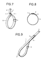
- the present invention relates to a method and apparatus for shaping loops such as metallic binding bands. Examples of such metallic binding bands are illustrated in Figs. 7 and 8.
- a metallic binding band 1 is composed of a binding section 2 wherein a band-shaped steel material cut to a prescribed length has been formed in a ring, a lever 3 wherein a band-shaped steel material of a prescribed length has been welded to the connected overlapping ends 2a of the binding section 2 and formed in a curved shape, and a retaining piece 4 for fixing the lever 3 wherein a band-shaped steel material cut to a prescribed length has been bent into the shape of a U and welded to a prescribed position on the binding section 2, with both ends bending around the outside of the ring formed by the binding section 2.
- the metallic binding band 1 is prepared by cutting the binding section 2, lever 3, and retaining piece 4 separately out of a long steel material, processing them appropriately, welding the retaining piece 4 onto the binding section 2, and welding the lever 3 to the overlapped section 2a of both ends of the binding section 2.
- the method of this invention aims at transforming pieces to be re-formed such as half-manufactured loop-shaped metallic binding bands into prescribed forms.
- a plurality of elongated materials such as wire rods are provided in parallel at prescribed intervals around a prescribed space having a prescribed diameter matching the final prescribed form for the metallic binding band.
- the diameter of the space prescribed by the wires is reduced by moving the wires radially inwardly towards each other to form a reduced diameter space.
- the reduced-diameter section is inserted into a loop-shaped starting piece.
- the reduced-diameter section is expanded by moving the wire rods radially outwardly away from each other and into contact with the starting piece. Pressure is then applied from within the space defined by the wire rods to transform the loop-shaped starting piece into the desired final prescribed form.
- a plurality of elongated materials such as wire rods, arranged at prescribed intervals to define an inner shape having a prescribed diameter to which a starting piece (a half-manufactured loop-shaped metallic binding band) is to be reformed, are fixed on a vertical wall at their back ends.
- a plurality of pressing plates which move vertically in the direction of elongation of the elongated materials are provided at or about the free forward ends of the elongated materials. When pressed against the free forward ends, the pressing plates reduce the diameter of the original shape prescribed by the elongated material to allow the front free ends of the elongated materials to be inserted within the starting piece having an approximate loop shape.
- a holding means (comprising a lower mold and a punch) is provided for holding the starting piece.
- a control piece is provided which travels in the direction of elongation of the elongated materials and within the space prescribed by the elongated materials. The plurality of elongated materials are pressed outwardly by the control piece against the starting piece to reform the starting piece to the original inner shape having a prescribed diameter defined by the elongated materials.
- An actuator e.g., a cylinder
- a close-off moving mechanism which drives a slide block supporting the elongated materials, control piece, actuator, etc., is provided to allow the holding means to come relatively close to and withdraw from the elongated materials inserted within the starting piece, thus facilitating entry of the elongated materials within the starting piece.
- Figs. 1 - 6 refer to an embodiment of the loop-shaped piece re-forming machine according to this invention, in which:
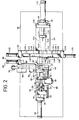
- Fig. 1 is a front plan view of a loop forming machine
- Fig. 2 a top plan view thereof.
- the illustrated forming machine 10 embodying this invention comprises a deflashing mechanism 12 for removing the flash from the lever 3 of a metallic binding band 1, a lever forming mechanism 14 for forming the lever 3 of the metallic binding band 1 into an arc, and a loop forming mechanism 16 for forming the binding section 2 of the metallic binding band 1 into a circle.
- a machine frame 18 supporting the forming machine 10 On the left side of a machine frame 18 supporting the forming machine 10, shown in Figs. 1 and 2, there are provided the deflashing mechanism 12 and the lever forming mechanism 14.
- a projection-shaped dovetail 20a is set in the longitudinal direction on a base 20.
- a dovetail groove 24a on the lower surface of a slide plate 24 engages the dovetail 20a on the upper surface of the base 20 so as to slide.
- a step 28 formed at the same height as the groove 26.
- On the dented groove 26 is provided an action board 30 which is guided by the dented groove 26 to travel freely in the dented groove 26 in the longitudinal direction.
- a mounting plate 32 (almost half of the mounting plate 32 is put on the step 28) is fixed on the step 28 at the front end of the slide plate 24.
- the upper surface of plate 32 is almost flush with the lower surface of the operating board 30a.
- Two bottomed holes 30b are bored in the longitudinal direction (backward) from the front end face of the action board 30 along the action board 30.
- Springs 34 are situated in these holes 30b so that the front ends of springs 34 in contact with the mounting plate 32 push the action board 30 backward (see Fig. 3).
- On the upper surface of the action board 30 and operating board 30a a groove-shaped dented section 30c extends in the backward direction.
- a fixed vertical wall 36 in contact with the back end of the base 20 supports a cylinder 38.
- the front end of the piston 38a of the cylinder 38 which is fixed on the vertical wall 36 and driven by air or oil pressure, is connected to the back end of the action board 30.
- a stopper block 40 is fixed on the slide plate 24 so as to bridge the dented groove 26.
- a screw lever 44 is longitudinally screwed on the block 12 fixed on the action board 30 which travels along the dented groove 26 of the slide plate 24. The back end of the screw lever 44 hits the stopper block 40 to set the retire limit of the action board 30.
- a locating piece 46 serves to determine the mounting position in putting the metallic binding band 1 on the mounting plate 32.
- This locating piece 46 is attached via a fixture 48 forming a trapezium (in plan view) fixed on the action board 30, with a part thereof over the mounting plate 32 of the step 28 on the slide plate 24.
- the portion of the locating piece 46 over the mounting plate 32 is gradually made thinner toward the middle and has a notch 46a provided which serves to locate the metallic binding band 1.
- the flat binding section 2 of the metallic binding band 1 is positioned at this notch 46a.
- a vertical wall 32a is provided facing the locating piece 46 on the mounting plate 32, and the front end of the lever 3 of the metallic binding band 1 hits the vertical wall 32a for positioning.
- a step 50 is formed on the slide plate side of the bending bed 22, at the same height as the step 28 on the slide plate 24.
- the action board 30 slides forward together with the mounting plate 32 since the springs 34 are exerting a pulling-apart force between the mounting plate 32 and the holes 30b of the action board 30.
- the slide plate 24 also slides together with the action board 30 since the slide plate 24 is connected with the mounting plate 32.
- the end face of the slide plate 24 is brought to collide with the end face of the bending bed 22 (at the same time the end face of the mounting plate 32 hits the vertical face 50a of the step 50).
- the mounting plate 32 is now on both the step 28 of the slide plate 24 and the step 50 of the bending bed 22.
- the action board 30 is pushed forward against the force of the springs 34 and, therefore, the flat metallic binding band 1 held by the notch 46a of the locating piece 46 slides on the mounting plate 32 to a prescribed position on the bending bed 22.
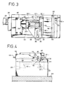
- a lower mold 52 which transforms the lever 3 into the shape of an arc.
- the lower mold 52 has a stepped section 52a corresponding in shape to the step at the junction between the lever 3 and the binding section 2.
- An eject pin 56a energized by a spring 54 projects movably and freely from the surface of the lower mold 52 (see Figs. 3 and 4).
- a punch 56 matching the lower mold 52 is fixed on a traveling block 60 which moves up and down along the supporting pillar 58 provided in parallel with the bending bed 22.
- This traveling block 60 has a bottom-closed hole 62 bored upward from the lower face of the traveling block 60, and a vertical rod piece 64 extending from the bending bed 22 enters this hole 62.
- a long spring 66 is provided around the rod piece 64 to energize the traveling block 60 upward (in the direction away from the bending bed 22) (see Fig. 5).
- a shaft 69 supports an arm 68, whose front end is in contact with the upper face of the traveling block 60 and whose back end is connected to the piston 70a of a cylinder 70.
- the deflashing mechanism 12 is provided on the supporting pillar 58 at the side of the base 20. This deflashing mechanism 12 will now be described.
- a fixing plate 80 is fixed on the supporting pillar 58 so that a side face of the fixing plate 80 is in contact with the traveling block 60.
- a tapered plane 80a at an angle of 45° is formed at the lower section of the fixing plate 80, and a rotary squashing body 82 is provided rotatably on the tapered plane 80a to squash the flash of the lever 3 of the metallic binding band 1.
- a radial bearing etc. may be used as the rotary squashing body 82.
- the flash is removed when the flash section of the lever 3 passes under the corner section 82a of the rotary squashing body 82.
- a supporting frame 84 (forming an L-shape in plan view) from the fixing plate 80 is fixed so as to surround the traveling block 60, serving as a guide for the traveling block 60.
- a stopper plate 86 is placed in front of the bending bed 22. This stopper plate 86 is guided by a guided groove (not shown) engraved on the machine frame 18 to enable the front of the bending bed 22 to be closed.
- the stopper plate 86 is connected to a piston 90a of a cylinder 90 attached on a fixing piece 88 fixed at the end edge section of the machine frame 18.
- This loop forming mechanism 16 is located on the right side of the machine frame 18 in Figs. 1 and 2.
- the loop forming mechanism 16 includes a base 92. On the upper face of the base 92 there is a projected dovetail 92a in the longitudinal direction. A dovetail groove 94a is formed on the lower face of a slide block 94, engaging slidably and freely with the dovetail 92a of the base 92 (see Fig. 6). A fixed plate 96 is provided vertically on the back section of base 92 to support a cylinder 98. The piston 98a of this cylinder 98 is connected to the slide block 94, the driving force of the cylinder 98 driving the slide block 94.
- a vertical wall 100 is provided on the back upper face of the slide block 94. In the middle of this vertical wall 100 a through-hole 102 is bored, and around this through-hole 102 a plurality of holes are bored to fix the back end of each of a plurality of wire rods 104.
- a cylinder block 108 is provided on the back face of the vertical wall 100. Cylinder block 108 supports a cylinder 110. A piston 110a of the cylinder 110 extends through the through-hole 102 of the vertical wall 100, and is connected to a driving bar 112. A disk-shaped control piece 114 is fixed at the front end of the driving bar 112.
- This control piece 114 has bored circularly around its circumference as many through-holes 116 as there are wire rods 104.
- the wire rods 104 extend through the through-holes 116, the front end of each wire rod 104 in the direction of the extensions being a free end.
- a guide wall 118 extending in the transverse direction is fixed on the front end face of the slide block 94.
- a cut section 119 is formed in the middle of this guide wall 118 to allow the wire rods 104 to extend forward.
- fixing pieces 120 At both ends of the guide wall 118 are attached fixing pieces 120, each of which fixes one of the cylinders 122.
- Pistons 122a of the cylinders 122 are connected to slide pieces 124.
- On the face of the slide pieces 124 in contact with the guide wall 118 are provided projected sections 124a, which engage with a dented groove 118a engraved in the transverse direction on the front face of the guide wall 118, allowing two slide pieces 124 to slide freely and mutually away or to approach.
- Pressing plates 126 and 128 are fixed respectively, on the front faces of the slide pieces 124.
- cut sections 126a and 128a which taper and are semicircular in respective middle sections.
- a guide plate 128b which is obtained by cutting a cylindrical body, whose diameter is reduced toward the front, along the axis thereof.
- front end sections of the wire rods 104 extending forward over the interval between the pressing plates 126 and 128, are pressed towards each other by the respective cut section 126a and cut section 128a to define a prescribed shape of reduced diameter (shown by two-dots chain line in Fig. 2).
- the forming machine according to this invention is constructed as described above. The action of the forming machine will be described below.
- the process described above enables the production of precision metallic binding band 1 composed of a binding section 2 shaped close to an exact circle and a lever 3 shaped in an arc.
- the loop forming mechanism of the forming machine given above is capable of transforming a loop-shaped material having a prescribed width into an exact circle.
- a plurality of wire rods have been employed to expand the binding section, but narrow strips, not in the form of rods or wire, may be employed.
- circular pieces like binding bands, elliptical, triangular, square, polygonal, and other shaped pieces may also be formed if the arrangement of the elongated materials and the form of the holes of the control piece are fitted to the form desired.
- the present invention is intended to transform loop-shaped materials (e.g., metallic binding bands) into any prescribed form by inserting a plurality of elongated materials (e.g., wire rods), previously pressed towards each other to define a cross-sectional space of reduced diameter, into a loop and then moving them outwardly to increase the diameter of the space they prescribe and into contact with the loop to re-shape the loop, thus resulting in various significant effects, for example, safe, simple and automatic formation of high-precision loop-shaped materials (e.g., metallic binding bands).
- a plurality of elongated materials e.g., wire rods
Landscapes
- Engineering & Computer Science (AREA)
- Mechanical Engineering (AREA)
- Basic Packing Technique (AREA)
- Bending Of Plates, Rods, And Pipes (AREA)
- Wire Processing (AREA)
Claims (11)
- Dispositif (10) pour reconformer la forme d'un élément de départ (1) approximativement en forme de boucle en une forme de boucle prescrite, comprenant:
des moyens de retenue (52, 56) pour maintenir un élément de départ (1);
une pluralité d'éléments allongés (104) disposés sensiblement parallèlement les uns aux autres à des intervalles prescrits pour définir un espace en forme de boucle prescrit présentant un premier diamètre, chacun de la pluralité desdits éléments allongés (104) comportant une extrémité arrière fixe et une extrémité avant libre;
plusieurs moyens de pression (126, 128) disposés autour des extrémités libres de la multiplicité d'éléments allongés (104), lesdits moyens de pression (126, 128) pouvant être déplacés (122) sensiblement perpendiculairement par rapport à la direction en longueur de la multiplicité d'éléments allongés (104) pour presser lesdites extrémités libres en direction les unes des autres, lesdites extrémités libres définissant un espace en forme de bouche réduite présentant un second diamètre plus petit que le premier diamètre;
des moyens (122) pour rétracter lesdits plusieurs moyens de pression après insertion des extrémités libres dans l'élément de départ (1), les extrémités libres s'écartant ainsi les unes des autres et venant en contact avec une surface interne de l'élément de départ (1); et
des moyens de commande (112, 114) pouvant se déplacer librement dans la direction en longueur des articles allongés (104) à l'intérieur de l'espace prescrit en forme de bouche défini par lesdits éléments allongés et comprenant un élément en forme de disque (114) coaxial auxdits éléments allongés (104) pour les presser radialement vers l'extérieur contre l'élément de départ (1) pour reconformer cet élément de départ (1) selon une forme qui correspond à ladite forme de bouche prescrite. - Dispositif selon la revendication 1, comprenant en outre un moyen d'arrêt (86) pour empêcher le dégagement de l'élément de départ (1) de la multiplicité d'éléments allongés (104), le moyen d'arrêt (86) pouvant être déplacé entre une configuration de retenue adjacente des extrémités libres de la multiplicité d'éléments allongés et une configuration de non retenue;
un élément d'actionnement (110) pour déplacer lesdits moyens de commande (114), le dispositif d'actionnement (110) comprenant un piston (110a);
une paroi verticale (100) comprenant une face avant et une face arrière, les extrémités arrière de la multiplicité d'éléments allongés (104) étant fixées à la face avant et le dispositif d'actionnement (110) étant relié à la face arrière; et
un trou traversant constitué dans la paroi verticale, le piston d'actionnement (110a) s'étendant à travers ce trou traversant et le long d'un point central de l'espace défini par ladite multiplicité d'éléments allongés (104). - Dispositif selon la revendication 1 ou 2, dans lequel la multiplicité d'éléments allongés (104) comprend des tiges de petit diamètre.
- Dispositif selon l'une quelconque des revendications précédentes, comprenant en outre:
des moyens de déplacement (98) pour déplacer les moyens de retenue (52, 56) et les rapprocher ou les écarter desdits éléments allongés pour faciliter l'insertion de leurs extrémités libres pressées dans l'élément de départ approximativement en forme de boucle alors que ledit élément de départ est maintenu par les moyens de retenue. - Dispositif selon la revendication 2, dans lequel les moyens de commande (112, 114) sont fixés à l'extrémité avant du piston (110a).
- Dispositif selon l'une quelconque des revendications précédentes, dans lequel lesdits plusieurs éléments de pression (126, 128) comprennent au moins deux plaques de pression (126, 128) mobiles dans la direction les rapprochant ou les éloignant de la multiplicité d'éléments allongés, lesdites plaques de pression étant décalées l'une par rapport à l'autre dans la direction de la longueur des éléments allongés, les plaques de pression comprenant des bords comportant des encoches en forme de V pour presser lesdites extrémités libres en direction les unes des autres de façon à former un faisceau au moyen desdites extrémités libres et les recouvrir.
- Dispositif selon l'une quelconque des revendications précédentes, dans lequel les moyens de retenue (52, 56) comprennent un mécanisme de mise en forme d'un levier (14) comprenant un moule supérieur (56) et une moule inférieur (52) pour maintenir un levier (3) de l'élément de départ (1) et impartir audit levier une forme arquée.
- Dispositif selon la revendication 7, comprenant en outre:
une plaque coulissante (24) mobile en direction la rapprochant ou l'éloignant du moule inférieur (52);
un bloc de montage (32) sur la plaque coulissante (24) pour monter l'élément de départ (1);
une plaque d'actionnement (30) sur la plaque coulissante (24) mobile en direction la rapprochant ou l'éloignant du bloc de montage (32);
un ressort (34) monté entre la plaque d'actionnement (30) et le bloc de montage (32);
un dispositif d'actionnement (38) relié à la plaque d'actionnement pour déplacer ladite plaque d'actionnement (30), de manière que lorsque le dispositif d'actionnement est entraîné de façon à déplacer la plaque d'actionnement en direction du moule inférieur (52), la plaque coulissante (24) est également déplacée par le ressort (34) jusqu'à ce que la plaque coulissante vienne heurter le moule inférieur, suite à quoi seule la plaque d'actionnement s'avance à l'encontre de la force élastique du ressort; et
une plaque d'alimentation s'étendant vers l'avant à partir de l'extrémité avant de la plaque d'actionnement pour faire avancer l'élément de départ depuis la plaque de montage vers le moule inférieur après que la plaque coulissante (24) ait heurté le moule inférieur (52),tandis que seule la plaque d'actionnement avarice à l'encontre de la force élastique du ressort. - Dispositif selon l'une quelconque des revendications précédentes, comprenant un moule supérieur (56) et un moule inférieur (52) pour maintenir un levier (3) de l'élément de départ (1),
et un mécanisme d'ébavurage (12) pour éliminer les bavures de l'élément de départ dans les moules supérieur et inférieur, lesdites bavures étant formées à une extrémité d'un levier de l'élément de départ en liaison avec une surface circonférentielle externe d'une section de liaison de l'élément de départ. - Procédé pour reconformer un élément de départ (1) approximativement en forme de boucle selon une forme de boucle prescrite, comprenant:
l'agencement de plusieurs éléments allongés (104) sensiblement parallèles les uns aux autres à des intervalles prescrits pour définir un espace de boucle prescrit présentant un premier diamètre;
disposer un élément en forme de disque (114) coaxialement auxdits éléments allongés (104);
réduire le diamètre de l'espace en forme de boucle déterminé par la multiplicité d'éléments allongés pour définir un espace en forme de boucle réduit présentant un second diamètre plus petit que le premier diamètre;
insérer la multiplicité d'éléments allongés (104) qui définissent un espace de boucle réduit présentant un second diamètre à l'intérieur de l'élément de départ; et
déplacer l'élément en forme de disque (114) axialement à l'intérieur de l'espace en forme de boucle défini par les éléments allongés (104) Pour les solliciter radialement vers l'extérieur, de façon à augmenter le diamètre de l'espace en boucle pour définir l'espace en forme de boucle prescrit présentant ledit premier diamètre, lesdits éléments allongés venant en contact avec une surface interne de l'élément de départ pendant cet élargissement et reconformant l'élément de départ approximativement en forme de boucle en la Forme de boucle prescrite. - Procédé selon la revendication 10, dans lequel la multiplicité d'éléments allongés (104) est constituée par des tiges de petit diamètre.
Applications Claiming Priority (2)
| Application Number | Priority Date | Filing Date | Title |
|---|---|---|---|
| JP134049/86 | 1986-06-10 | ||
| JP61134049A JPH0651214B2 (ja) | 1986-06-10 | 1986-06-10 | ループ状被成形部材の成形機 |
Publications (3)
| Publication Number | Publication Date |
|---|---|
| EP0249341A2 EP0249341A2 (fr) | 1987-12-16 |
| EP0249341A3 EP0249341A3 (en) | 1990-01-31 |
| EP0249341B1 true EP0249341B1 (fr) | 1993-03-17 |
Family
ID=15119168
Family Applications (1)
| Application Number | Title | Priority Date | Filing Date |
|---|---|---|---|
| EP87304244A Expired - Lifetime EP0249341B1 (fr) | 1986-06-10 | 1987-05-13 | Procédé et dispositif pour mettre en forme des bouches telles que des rubans de liaison métalliques |
Country Status (7)
| Country | Link |
|---|---|
| US (2) | US4831863A (fr) |
| EP (1) | EP0249341B1 (fr) |
| JP (1) | JPH0651214B2 (fr) |
| KR (1) | KR910003176B1 (fr) |
| AU (1) | AU583722B2 (fr) |
| CA (1) | CA1296989C (fr) |
| DE (1) | DE3784780T2 (fr) |
Families Citing this family (4)
| Publication number | Priority date | Publication date | Assignee | Title |
|---|---|---|---|---|
| JP4402253B2 (ja) * | 2000-04-25 | 2010-01-20 | 株式会社ミハマ | 締め付けバンドの製造装置及び製造方法 |
| CN103506527B (zh) * | 2013-08-28 | 2015-09-09 | 宁波庆昌镒万汽车配件有限公司 | 一种钢丝挤压装置 |
| CN104707918B (zh) * | 2015-02-16 | 2016-08-24 | 奥美森智能装备股份有限公司 | 折弯机的夹持机构 |
| CN115069912B (zh) * | 2022-07-20 | 2022-12-13 | 江苏克莱德激光技术有限责任公司 | 一种管道扩径装置 |
Family Cites Families (14)
| Publication number | Priority date | Publication date | Assignee | Title |
|---|---|---|---|---|
| US1153480A (en) * | 1915-03-26 | 1915-09-14 | E & B Holmes Machinery Company | Hoop expanding and flaring machine. |
| FR494042A (fr) * | 1917-12-26 | 1919-08-28 | Societe M Pintel Fils Et Cie | Appareil pour la fabrication de tubes de radiateurs "nid d'abeilles" |
| US1494128A (en) * | 1921-06-11 | 1924-05-13 | Power Specialty Co | Method and apparatus for expanding tubes |
| US1669053A (en) * | 1926-09-13 | 1928-05-08 | Charles W Hamel | Apparatus for positioning elastic tubular coverings on the handles of playing clubs |
| DE474991C (de) * | 1928-03-07 | 1929-10-22 | Eduard Schlamp Vom Hofe | Spreizvorrichtung zum Aufweiten und Aufziehen schlauchartiger, insbesondere elastischer Isolierteile auf elektrische Leitungen |
| US1955949A (en) * | 1928-04-21 | 1934-04-24 | Parke Davis & Co | Machine for placing sealing caps on bottles |
| FR977958A (fr) * | 1942-11-27 | 1951-04-09 | Louvroil Montbard Aulnoye | Procédé et dispositif d'expansion au banc de tubes métalliques |
| US2740456A (en) * | 1953-10-05 | 1956-04-03 | Jr Claude Laval | Expander tools |
| US3095029A (en) * | 1960-10-31 | 1963-06-25 | Robert M Lambert | Can crimper |
| AT245793B (de) * | 1962-10-31 | 1966-03-10 | Shell Int Research | Vorrichtung zum Aufbringen eines dehnbaren Schlauches auf einen Körper, dessen Endteil einen größeren Querschnitt als der Schlauch aufweist |
| US3281927A (en) * | 1964-06-22 | 1966-11-01 | Buslaff Rolland | Tool for dilating elastic rings and tubes |
| NL7906317A (nl) * | 1979-08-21 | 1981-02-24 | Doornes Transmissie Bv | Werkwijze en inrichting voor het oprekken van een eind- loze metalen band. |
| US4530231A (en) * | 1980-07-03 | 1985-07-23 | Apx Group Inc. | Method and apparatus for expanding tubular members |
| ATE24679T1 (de) * | 1982-03-12 | 1987-01-15 | Salter & Co Ltd G | Verfahren und vorrichtung zum herstellen von sprengringen. |
-
1986
- 1986-06-10 JP JP61134049A patent/JPH0651214B2/ja not_active Expired - Lifetime
-
1987
- 1987-03-25 US US07/030,712 patent/US4831863A/en not_active Expired - Lifetime
- 1987-04-07 AU AU71161/87A patent/AU583722B2/en not_active Ceased
- 1987-04-09 KR KR1019870003391A patent/KR910003176B1/ko not_active Expired
- 1987-05-13 DE DE8787304244T patent/DE3784780T2/de not_active Expired - Fee Related
- 1987-05-13 EP EP87304244A patent/EP0249341B1/fr not_active Expired - Lifetime
- 1987-05-19 CA CA000537356A patent/CA1296989C/fr not_active Expired - Fee Related
- 1987-10-26 US US07/113,567 patent/US4813262A/en not_active Expired - Lifetime
Also Published As
| Publication number | Publication date |
|---|---|
| KR880000164A (ko) | 1988-03-23 |
| DE3784780D1 (de) | 1993-04-22 |
| AU583722B2 (en) | 1989-05-04 |
| US4813262A (en) | 1989-03-21 |
| AU7116187A (en) | 1987-12-17 |
| US4831863A (en) | 1989-05-23 |
| DE3784780T2 (de) | 1993-08-12 |
| EP0249341A3 (en) | 1990-01-31 |
| EP0249341A2 (fr) | 1987-12-16 |
| JPS62289334A (ja) | 1987-12-16 |
| JPH0651214B2 (ja) | 1994-07-06 |
| KR910003176B1 (ko) | 1991-05-22 |
| CA1296989C (fr) | 1992-03-10 |
Similar Documents
| Publication | Publication Date | Title |
|---|---|---|
| US20010032870A1 (en) | Clamping band manufacturing machine and method of manufacturing clamping band | |
| EP0249341B1 (fr) | Procédé et dispositif pour mettre en forme des bouches telles que des rubans de liaison métalliques | |
| US3910092A (en) | Metal expanding machine | |
| US5396786A (en) | Machine and method for manufacturing crossover fittings | |
| SU728740A3 (ru) | Способ изготовлени зубчатого полюсного наконечника | |
| US4352281A (en) | Method and apparatus for bending pipes | |
| JPH0813377B2 (ja) | 管成形プレス装置 | |
| US4361025A (en) | Wire bending machine | |
| EP0023423B1 (fr) | Procédé et dispositif pour déformer la tôle | |
| US1448567A (en) | Amd frederick c | |
| JP3962156B2 (ja) | クリップ成形方法及びクリップ成形装置 | |
| JP5783598B2 (ja) | パイプ状部材の曲げ成形装置 | |
| US5086637A (en) | Apparatus for forming metallic binding bands | |
| JPH0747433A (ja) | ブランク材成形方法 | |
| KR100307128B1 (ko) | 파스너 체인 마무리 장치 | |
| CA1042644A (fr) | Methode de faconnage d'un collier de fixation a vis de serrage | |
| JPH03275238A (ja) | ループ状被成形部材の成形方法および形成機 | |
| CN111545692A (zh) | 一种弹簧卡箍、弹簧卡箍的成型设备及成型方法 | |
| EP4108358B1 (fr) | Appareil, machine et procédé pour déformer les extrémités opposées d'une pièce de fil | |
| JPS582015B2 (ja) | 熱交換器,管−金属条片素子処理のための方法および装置 | |
| US3333450A (en) | Bending machine | |
| JPH054893Y2 (fr) | ||
| SU1496869A1 (ru) | Прижим дл центрировани обрабатываемого материала в штампе | |
| SU774730A1 (ru) | Устройство дл последовательной гибки заготовок в обод | |
| SU604634A1 (ru) | Устройство дл дозировани заготовок по оъему при резке |
Legal Events
| Date | Code | Title | Description |
|---|---|---|---|
| PUAI | Public reference made under article 153(3) epc to a published international application that has entered the european phase |
Free format text: ORIGINAL CODE: 0009012 |
|
| AK | Designated contracting states |
Kind code of ref document: A2 Designated state(s): CH DE FR GB IT LI SE |
|
| PUAL | Search report despatched |
Free format text: ORIGINAL CODE: 0009013 |
|
| AK | Designated contracting states |
Kind code of ref document: A3 Designated state(s): CH DE FR GB IT LI SE |
|
| 17P | Request for examination filed |
Effective date: 19900321 |
|
| 17Q | First examination report despatched |
Effective date: 19911106 |
|
| GRAA | (expected) grant |
Free format text: ORIGINAL CODE: 0009210 |
|
| AK | Designated contracting states |
Kind code of ref document: B1 Designated state(s): CH DE FR GB IT LI SE |
|
| REF | Corresponds to: |
Ref document number: 3784780 Country of ref document: DE Date of ref document: 19930422 |
|
| ET | Fr: translation filed | ||
| ITF | It: translation for a ep patent filed | ||
| PLBE | No opposition filed within time limit |
Free format text: ORIGINAL CODE: 0009261 |
|
| STAA | Information on the status of an ep patent application or granted ep patent |
Free format text: STATUS: NO OPPOSITION FILED WITHIN TIME LIMIT |
|
| 26N | No opposition filed | ||
| EAL | Se: european patent in force in sweden |
Ref document number: 87304244.4 |
|
| PGFP | Annual fee paid to national office [announced via postgrant information from national office to epo] |
Ref country code: CH Payment date: 20000524 Year of fee payment: 14 |
|
| PG25 | Lapsed in a contracting state [announced via postgrant information from national office to epo] |
Ref country code: LI Free format text: LAPSE BECAUSE OF NON-PAYMENT OF DUE FEES Effective date: 20010612 Ref country code: CH Free format text: LAPSE BECAUSE OF NON-PAYMENT OF DUE FEES Effective date: 20010612 |
|
| REG | Reference to a national code |
Ref country code: GB Ref legal event code: IF02 |
|
| REG | Reference to a national code |
Ref country code: CH Ref legal event code: PL |
|
| PGFP | Annual fee paid to national office [announced via postgrant information from national office to epo] |
Ref country code: FR Payment date: 20050419 Year of fee payment: 19 |
|
| PGFP | Annual fee paid to national office [announced via postgrant information from national office to epo] |
Ref country code: GB Payment date: 20050503 Year of fee payment: 19 |
|
| PGFP | Annual fee paid to national office [announced via postgrant information from national office to epo] |
Ref country code: SE Payment date: 20050516 Year of fee payment: 19 |
|
| PGFP | Annual fee paid to national office [announced via postgrant information from national office to epo] |
Ref country code: DE Payment date: 20050531 Year of fee payment: 19 |
|
| PG25 | Lapsed in a contracting state [announced via postgrant information from national office to epo] |
Ref country code: GB Free format text: LAPSE BECAUSE OF NON-PAYMENT OF DUE FEES Effective date: 20060513 |
|
| PG25 | Lapsed in a contracting state [announced via postgrant information from national office to epo] |
Ref country code: SE Free format text: LAPSE BECAUSE OF NON-PAYMENT OF DUE FEES Effective date: 20060514 |
|
| PGFP | Annual fee paid to national office [announced via postgrant information from national office to epo] |
Ref country code: IT Payment date: 20060531 Year of fee payment: 20 |
|
| PG25 | Lapsed in a contracting state [announced via postgrant information from national office to epo] |
Ref country code: DE Free format text: LAPSE BECAUSE OF NON-PAYMENT OF DUE FEES Effective date: 20061201 |
|
| EUG | Se: european patent has lapsed | ||
| GBPC | Gb: european patent ceased through non-payment of renewal fee |
Effective date: 20060513 |
|
| REG | Reference to a national code |
Ref country code: FR Ref legal event code: ST Effective date: 20070131 |
|
| PG25 | Lapsed in a contracting state [announced via postgrant information from national office to epo] |
Ref country code: FR Free format text: LAPSE BECAUSE OF NON-PAYMENT OF DUE FEES Effective date: 20060531 |