EP0250907A2 - Strain relieve device for ribbon cables - Google Patents
Strain relieve device for ribbon cables Download PDFInfo
- Publication number
- EP0250907A2 EP0250907A2 EP87108028A EP87108028A EP0250907A2 EP 0250907 A2 EP0250907 A2 EP 0250907A2 EP 87108028 A EP87108028 A EP 87108028A EP 87108028 A EP87108028 A EP 87108028A EP 0250907 A2 EP0250907 A2 EP 0250907A2
- Authority
- EP
- European Patent Office
- Prior art keywords
- housing part
- pin
- insulating
- insulating material
- landline
- Prior art date
- Legal status (The legal status is an assumption and is not a legal conclusion. Google has not performed a legal analysis and makes no representation as to the accuracy of the status listed.)
- Withdrawn
Links
- 239000011810 insulating material Substances 0.000 claims abstract description 9
- 230000005405 multipole Effects 0.000 claims 1
- 238000011161 development Methods 0.000 description 6
- 230000018109 developmental process Effects 0.000 description 6
- 238000009413 insulation Methods 0.000 description 2
- 238000005452 bending Methods 0.000 description 1
- 238000003780 insertion Methods 0.000 description 1
- 230000037431 insertion Effects 0.000 description 1
- 238000004519 manufacturing process Methods 0.000 description 1
- 238000000034 method Methods 0.000 description 1
- 238000003825 pressing Methods 0.000 description 1
Images
Classifications
-
- H—ELECTRICITY
- H01—ELECTRIC ELEMENTS
- H01R—ELECTRICALLY-CONDUCTIVE CONNECTIONS; STRUCTURAL ASSOCIATIONS OF A PLURALITY OF MUTUALLY-INSULATED ELECTRICAL CONNECTING ELEMENTS; COUPLING DEVICES; CURRENT COLLECTORS
- H01R13/00—Details of coupling devices of the kinds covered by groups H01R12/70 or H01R24/00 - H01R33/00
- H01R13/58—Means for relieving strain on wire connection, e.g. cord grip, for avoiding loosening of connections between wires and terminals within a coupling device terminating a cable
- H01R13/5804—Means for relieving strain on wire connection, e.g. cord grip, for avoiding loosening of connections between wires and terminals within a coupling device terminating a cable comprising a separate cable clamping part
- H01R13/5812—Means for relieving strain on wire connection, e.g. cord grip, for avoiding loosening of connections between wires and terminals within a coupling device terminating a cable comprising a separate cable clamping part the cable clamping being achieved by mounting the separate part on the housing of the coupling device
-
- H—ELECTRICITY
- H02—GENERATION; CONVERSION OR DISTRIBUTION OF ELECTRIC POWER
- H02G—INSTALLATION OF ELECTRIC CABLES OR LINES, OR OF COMBINED OPTICAL AND ELECTRIC CABLES OR LINES
- H02G15/00—Cable fittings
- H02G15/007—Devices for relieving mechanical stress
Definitions
- the invention relates to a device for strain relief of multi-core electrical landlines on a housing part of an electrical component or device.
- the invention has for its object to provide a simple strain relief, in which the landline can be fixed without spending a lot of time and which enables a straight wire run.
- Such landlines serve, for example, as connecting lines between telephone systems and overhead line masts. These landlines have cores of increased strength and cross-section. Bending the cables or clamping them too tight increases the risk of breakage due to the higher brittleness.
- the spike-like insulating material is a simple part. The insertion into the connecting web is a simple straightforward process that can be carried out with a simple tool. The strain relief has no or only a minor effect on the wire core.
- the round cross section of the insulating pin according to claim 2 is easy to manufacture. Sharp cuts in the web are avoided, which reduces the risk of tearing open the insulation.
- the development according to claim 3 can be realized particularly inexpensively.
- fixing the cable it is first placed over the mandrel and pressed against its base. This pierces the insulation so that the cable is secured against longitudinal pull.
- the mandrel can have transverse ribs which make it difficult to pull out the line.
- a plurality of landlines can be attached in parallel to each other on the terminal block. Since the insulating pin can have a small width, it is possible, for example, two to attach single-core ridge cables individually and closely adjacent to the terminal block.
- a landline 1 is inserted into a housing part 2 of a terminal block for the landlines 1.
- a thorn-like tapered plastic pin 3 is held in a shaft above the landline 1.
- the tip of the insulating material pin 3 points to the web line 1.
- the insulating material pin 3 has a widespread foot end 5, into which a transverse groove 6 is embedded.
- a cam-like projection 7 of the shaft 4 engages in this, so that the insulating pin 3 is held in a defined position.
- the tip of the insulating pin 3 is directed towards a conical hole 8 in a bottom part 9 of the housing part 2.
- FIG. 2 shows another view of the parts according to FIG. 1.
- the two-wire landline 1 lies between two intermediate walls 10 of the housing part 2 centrally over the conical hole 8 of the bottom part 9.
- the hole 8 widens towards the insulating pin 3.
- Fig. 2 and in Fig. 3 are the Parts shown in their end position.
- the tip of the insulating material pin 3 is pierced through the connecting web 11 of the web line 1 and pressed into the conical hole 8 of the base part 9.
- the insulating pin 3 is provided with circumferential transverse ribs that taper towards the tip.
- the largest diameter of the transverse ribs 12 is somewhat larger than the narrowest diameter of the conical hole 8.
- the insulating pin 3 is pressed into the conical hole 8, the parts yield elastically to one another.
- the insulating pin 3 is pushed through the hole until the widespread foot end 5 rests on the landline 1.
- One of the transverse ribs then engages behind the bottom part 9, so that the insulating pin 3 is held firmly in the hole.
- a plurality of transverse ribs 12 arranged one above the other make it possible to fasten web lines of different thicknesses.
- Pressing the insulating pin 3 out of its latching position in the shaft 4 can e.g. by means of a stamp 13 indicated by dash-dotted lines.
- the shaft 4 pictures a guide for the extended foot part 5, so that the insulating pin 3 can easily hit the conical hole 8 in the bottom part 9.
Landscapes
- Installation Of Indoor Wiring (AREA)
- Insulated Conductors (AREA)
- Insertion Pins And Rivets (AREA)
- Insertion, Bundling And Securing Of Wires For Electric Apparatuses (AREA)
- Insulating Bodies (AREA)
Abstract
Zur Zugentlastung einer Stegleitung (1) an einem Gehäuseteil (2) wird ein dornartiger Isolierstoffzapfen (3) durch den Verbindungssteg (11) der Stegleitung (1) gestochen und in ein konisches Loch (8) des Gehäuseteiles (2) eingedrückt. Dadurch wird die Stegleitung (1) zugentlastet, ohne daß die Adern der Stegleitung (1) verformt werden.In order to relieve the strain on a landline (1) on a housing part (2), a thorn-like insulating material pin (3) is pierced through the connecting web (11) of the landline (1) and pressed into a conical hole (8) in the housing part (2). As a result, the landline (1) is relieved of strain without the wires of the landline (1) being deformed.
Description
Die Erfindung bezieht sich auf eine Einrichtung zur Zugentlastung von mehradrigen elektrischen Stegleitungen an einem Gehäuseteil eines elektrischen Bauteiles oder Gerätes.The invention relates to a device for strain relief of multi-core electrical landlines on a housing part of an electrical component or device.
Es ist bekannt, elektrische Leitungen durch Klemmen an Gehäuseteilen festzulegen. Dabei können die Leitungen mäanderförmig gebogen und an den Gehäuseteilen mehrfach umgelenkt sein, um die Reibungskräfte zu erhöhen.It is known to fix electrical lines by clamping on housing parts. The lines can be bent in a meandering shape and deflected several times on the housing parts in order to increase the frictional forces.
Stegleitungen von großem Durchmesser und hartem Kern lassen sich nur schwer biegen.Bar cables of large diameter and hard core are difficult to bend.
Der Erfindung liegt die Aufgabe zugrunde, eine einfache Zugentlastung zu schaffen, bei der die Stegleitung ohne hohen Zeitaufwand festgelegt werden kann und die einen gestreckten Drahtverlauf ermöglicht.The invention has for its object to provide a simple strain relief, in which the landline can be fixed without spending a lot of time and which enables a straight wire run.
Diese Aufgabe wird durch die Erfindung gemäß Anspruch 1 gelöst. Derartige Stegleitungen dienen z.B. als Verbindungsleitungen zwischen Telefonanlagen und Freileitungsmasten. Diese Stegleitungen haben Kerne von erhöhter Festigkeit und erhöhtem Querschnitt. Ein Verbiegen der Leitungen oder ein zu festes Einklemmen vergrößert wegen der höheren Sprödigkeit die Bruchgefahr. Der dornartige Isolierstoffzapfen stellt ein einfaches Teil dar. Das Einstechen in den Verbindungssteg ist ein einfacher geradliniger Vorgang, der mit einem einfachen Werkzeug durchgeführt werden kann. Die Zugentlastung wirkt sich dabei nicht oder allenfalls geringfügig auf den Drahtkern aus. Vorteilhafte Weiterbildungen der Erfindung sind in den Ansprüchen 2 bis 7 gekennzeichnet:This object is achieved by the invention according to claim 1. Such landlines serve, for example, as connecting lines between telephone systems and overhead line masts. These landlines have cores of increased strength and cross-section. Bending the cables or clamping them too tight increases the risk of breakage due to the higher brittleness. The spike-like insulating material is a simple part. The insertion into the connecting web is a simple straightforward process that can be carried out with a simple tool. The strain relief has no or only a minor effect on the wire core. Advantageous developments of the invention are characterized in
Der runde Querschnitt des Isolierstoffzapfens nach Anspruch 2 läßt sich einfach herstellen. Es werden scharfe Einschnitte in den Steg vermieden, was die Gefahr des Aufreißens der Isolation verringert.The round cross section of the insulating pin according to
Die Weiterbildung nach Anspruch 3 läßt sich besonders kostengünstig verwirklichen. Beim Festlegen der Leitung wird diese zunächst über den Dorn gelegt und gegen dessen Fuß gedrückt. Dabei durchsticht dieser die Isolation, so daß die Leitung gegen longitudinalen Zug gesichert ist. Der Dorn kann Querrippen aufweisen, die ein Herausziehen der Leitung erschweren.The development according to
Durch die Weiterbildung nach Anspruch 4 ist es möglich, die Leitung zunächst lagerichtig auf das Gehäuseteil aufzulegen und sodann durch Einstechen des Isolierstoffzapfens zu fixieren.Through the development according to
Durch die Weiterbildung nach Anspruch 5 legt sich der verbreitete Fuß des Zapfens flach über die Stegleitung, so daß diese auch in der Längsrichtung des Zapfens sicher gehalten ist.Through the development according to
Die Weiterbildung nach Anspruch 6 ermöglicht es, die Zapfen bereits werkseitig an dem Gehäuse lose zu fixieren. Beim Befestigen der Stegleitung befindet sich der Isolierstoffzapfen bereits in der richtigen Lage, so daß er lediglich durch eine einfache Hubbewegung in den Verbindungssteg eingedrückt wird.The development according to
Durch die Weiterbildung nach Anspruch 7 können mehrere Stegleitungen parallel nebeneinander an der Anschlußleiste befestigt werden. Da der Isolierstoffzapfen eine geringe Breite aufweisen kann, ist es möglich, z.b. zwei adrige Stegleitungen einzeln und eng benachbart an der Anschlußleiste zu befestigen.Through the development according to
Im folgenden wird die Erfindung anhand eines in der Zeichnung dargestellten Ausführungsbeispieles näher erläutert:
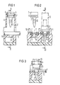
- Fig. 1 zeigt einen Schnitt durch ein Gehäuseteil einer Anschlußleiste für Stegleitungen mit einem Isolierstoffzapfen und einer Stegleitung,
- Fig. 2 einen Schnitt durch die Teile nach Fig. 1 entlang der Linie II-II in Fig. 1, wobei eine benachbarte Stegleitung in einer späteren Montagephase dargestellt ist,
- Fig. 3 einen Schnitt durch die Teile nach Fig. 2 entlang der Linie III-III in Fig. 2.
- 1 shows a section through a housing part of a connection strip for landlines with an insulating pin and a landline,
- 2 shows a section through the parts according to FIG. 1 along the line II-II in FIG. 1, an adjacent land line being shown in a later assembly phase,
- 3 shows a section through the parts according to FIG. 2 along the line III-III in FIG. 2.
Nach Fig. 1 ist eine Stegleitung 1 in ein Gehäuseteil 2 einer Anschlußleiste für die Stegleitungen 1 eingelegt. Ein dornartig zugespitzter Kunststoffzapfen 3 ist in einem Schacht über der Stegleitung 1 gehalten. Dabei weist die Spitze des Isolierstoffzapfens 3 auf die Stegleitung 1. Der Isolierstoffzapfen 3 weist ein verbreitetes Fußende 5 auf, in das eine Querrille 6 eingelassen ist. In diese greift ein nockenartiger Vorsprung 7 des Schachtes 4 ein, so daß der Isolierstoffzapfen 3 in einer definierten Lage gehalten wird. Dabei ist die Spitze des Isolierstoffzapfens 3 auf ein konisches Loch 8 in einem Bodenteil 9 des Gehäuseteiles 2 gerichtet.1, a landline 1 is inserted into a
Die linke Seite der Fig. 2 zeigt eine andere Ansicht der Teile nach Fig. 1. Die zweiadrige Stegleitung 1 liegt zwischen zwei Zwischenwänden 10 des Gehäuseteiles 2 zentrisch über dem konischen Loch 8 des Bodenteiles 9 auf. Das Loch 8 erweitert sich zum Isolierstoffzapfen 3 hin.The left-hand side of FIG. 2 shows another view of the parts according to FIG. 1. The two-wire landline 1 lies between two
In der rechten Hälfte der Fig. 2 und in Fig. 3 sind die Teile in ihrer Endstellung dargestellt. Der Isolierstoffzapfen 3 ist mit seiner Spitze durch den Verbindungssteg 11 der Stegleitung 1 gestochen und in das konische Loch 8 des Bodenteiles 9 eingedrückt. Der Isolierstoffzapfen 3 ist mit umlaufenden Querrippen versehen, die sich zur Spitze hin verjüngen. Dabei ist der größte Durchmesser der Querrippen 12 etwas größer als der engste Durchmesser des konischen Loches 8. Beim Eindrücken des Isolierstoffzapfens 3 in das konische Loch 8 geben die Teile gegenseitig elastisch nach. Der Isolierstoffzapfen 3 wird so weit durch das Loch hindurchgedrückt, bis das verbreitete Fußende 5 an der Stegleitung 1 anliegt. Eine der Querrippen hintergreift dann das Bodenteil 9, so daß der Isolierstoffzapfen 3 fest in dem Loch gehalten wird. Mehrere übereinander angeordnete Querrippen 12 ermöglichen es, Stegleitungen unterschiedlicher Dicke zu befestigen.In the right half of Fig. 2 and in Fig. 3 are the Parts shown in their end position. The tip of the
Das Herunterdrücken des Isolierstoffzapfens 3 aus seiner Raststellung in dem Schacht 4 kann z.B. mittels eines strichpunktiert angedeuteten Stempels 13 erfolgen. Dabei bilder der Schacht 4 eine Führung für das verlängerte Fußteil 5, so daß der Isolierstoffzapfen 3 ohne Schwierigkeiten das konische Loch 8 im Bodenteil 9 treffen kann.Pressing the insulating
Claims (7)
dadurch gekennzeichnet,
daß ein dornartiger Isolierstoffzapfen (3) transversal durch einen Verbindungssteg (11) der Stegleitung (19 gestochen und an dem Gehäuseteil (2) befestigt ist.1. Device for strain relief of multi-core electrical ridge cables on a housing part of an electrical component or device,
characterized by
that a thorn-like insulating material pin (3) is transversely pierced by a connecting web (11) of the web line (19) and fastened to the housing part (2).
dadurch gekennzeichnet,
daß der Isolierstoffzapfen (3) im Bereich des Verbindungssteges (11) einen runden Querschnitt aufweist.2. Device according to claim 1,
characterized by
that the insulating material pin (3) has a round cross section in the region of the connecting web (11).
dadurch gekennzeichnet,
daß der Isolierstoffzapfen an dem Gehäuseteil angespritzt ist.3. Device according to claim 1 or 2,
characterized by
that the insulating pin is molded onto the housing part.
dadurch gekennzeichnet,
daß der Isolierstoffzapfen (3) als separates Element ausgebildet und klemmend in ein z.B. konisches Loch (8) des Gehäuseteiles (2) eingesetzt ist und in diesem Bereich mit widerhakenartigen Querrippen (12) versehen ist.4. Device according to claim 1 or 2,
characterized by
that the insulating pin (3) is designed as a separate element and is inserted in a clamping manner into, for example, a conical hole (8) in the housing part (2) and is provided with barb-like transverse ribs (12) in this area.
dadurch gekennzeichnet,
daß der Isolierstoffzapfen (3) über der Stegleitung ein stufenförmig verbreitertes Fußteil (5) aufweist.5. Device according to claim 1, 2 or 4,
characterized by
that the Isolierstoffzapfen (3) has a step-widened base (5) over the landline.
dadurch gekennzeichnet,
daß der Isolierstoffzapfen (3) in seinem Fußteil (5) zumindest eine Querrille (6) aufweist und vor dem Durchstechen des Verbindungssteges (11) in einem Halteschacht (4) des Gehäuseteiles (2) fixiert ist, der mit zumindest einer nockenartigen Erhebung (7) in die Querrille (6) hineinragt.6. Device according to claim 5,
characterized by
that the insulating material pin (3) has at least one transverse groove (6) in its foot part (5) and in a holding shaft (4) before the piercing of the connecting web (11) of the housing part (2) is fixed, which projects into the transverse groove (6) with at least one cam-like elevation (7).
daß das Gehäuseteil (2) als Grundkörper einer mehrpoligen Anschlußleiste für die Stegleitungen (1) ausgebildet ist.7. Device according to one of the preceding claims, characterized in
that the housing part (2) is designed as a base body of a multi-pole terminal block for the landlines (1).
Applications Claiming Priority (2)
| Application Number | Priority Date | Filing Date | Title |
|---|---|---|---|
| DE3621214 | 1986-06-25 | ||
| DE3621214 | 1986-06-25 |
Publications (2)
| Publication Number | Publication Date |
|---|---|
| EP0250907A2 true EP0250907A2 (en) | 1988-01-07 |
| EP0250907A3 EP0250907A3 (en) | 1988-09-14 |
Family
ID=6303625
Family Applications (1)
| Application Number | Title | Priority Date | Filing Date |
|---|---|---|---|
| EP87108028A Withdrawn EP0250907A3 (en) | 1986-06-25 | 1987-06-03 | Strain relieve device for ribbon cables |
Country Status (3)
| Country | Link |
|---|---|
| EP (1) | EP0250907A3 (en) |
| JP (1) | JPS6314495A (en) |
| AU (1) | AU7464287A (en) |
Cited By (2)
| Publication number | Priority date | Publication date | Assignee | Title |
|---|---|---|---|---|
| GB2342508A (en) * | 1998-07-08 | 2000-04-12 | R W Data Ltd | Gripping electrical cables |
| EP2999054A1 (en) * | 2014-09-22 | 2016-03-23 | Tyco Electronics Simel S.A.S. | Binding screw for a wire connection assembly and wire connection assembly |
Families Citing this family (1)
| Publication number | Priority date | Publication date | Assignee | Title |
|---|---|---|---|---|
| JPH11300608A (en) * | 1998-04-20 | 1999-11-02 | Nec Corp | Chemical mechanical polishing equipment |
Family Cites Families (1)
| Publication number | Priority date | Publication date | Assignee | Title |
|---|---|---|---|---|
| DE3543257C2 (en) * | 1985-12-06 | 1994-10-13 | Siemens Ag | Ribbon cable connector |
-
1987
- 1987-06-03 EP EP87108028A patent/EP0250907A3/en not_active Withdrawn
- 1987-06-15 JP JP62147188A patent/JPS6314495A/en active Pending
- 1987-06-24 AU AU74642/87A patent/AU7464287A/en not_active Abandoned
Cited By (5)
| Publication number | Priority date | Publication date | Assignee | Title |
|---|---|---|---|---|
| GB2342508A (en) * | 1998-07-08 | 2000-04-12 | R W Data Ltd | Gripping electrical cables |
| GB2342508B (en) * | 1998-07-08 | 2002-08-07 | R W Data Ltd | Gripping of electrical cables |
| EP2999054A1 (en) * | 2014-09-22 | 2016-03-23 | Tyco Electronics Simel S.A.S. | Binding screw for a wire connection assembly and wire connection assembly |
| WO2016045825A1 (en) * | 2014-09-22 | 2016-03-31 | Tyco Electronics Simel Sas | Binding screw for a wire connection assembly and wire connection assembly |
| US10135157B2 (en) | 2014-09-22 | 2018-11-20 | Tyco Electronics Simel Sas | Binding screw for a wire connection assembly and wire connection assembly |
Also Published As
| Publication number | Publication date |
|---|---|
| JPS6314495A (en) | 1988-01-21 |
| AU7464287A (en) | 1988-01-07 |
| EP0250907A3 (en) | 1988-09-14 |
Similar Documents
| Publication | Publication Date | Title |
|---|---|---|
| DE2120838C3 (en) | Electrical connector | |
| DE2928321A1 (en) | ELECTRICAL TERMINAL CONTACT | |
| DE3239708C2 (en) | ||
| DE2204924A1 (en) | Electrical connector assembly | |
| DE2826978A1 (en) | SCREWLESS ELECTRICAL TERMINAL | |
| DE2413174B2 (en) | Electrical connector | |
| DE19633933A1 (en) | Connector for flat cable | |
| DE2610461C3 (en) | Device and method for producing a contact free of soldering, screwing and stripping on a fixed connection element, in particular for telecommunications line technology | |
| DE1765470B2 (en) | Electrical connector | |
| DE2342408C3 (en) | ||
| DE2342408A1 (en) | ELECTRICAL TERMINAL CONNECTOR | |
| DE2619558C2 (en) | Electrical connector | |
| DE2254318C3 (en) | Clamp contact | |
| DE2906031A1 (en) | SELF-CONTACTING ELECTRICAL CONNECTION DEVICE | |
| DE10321184A1 (en) | Contacting device for flexible ribbon cables | |
| DE69319259T2 (en) | Improved contacts for the connection of coil windings | |
| EP0250907A2 (en) | Strain relieve device for ribbon cables | |
| DE19604615C1 (en) | Contacting device e.g. for non-stripped flexible circular conductor e.g. for communication equipment | |
| DE102007052462A1 (en) | Printed circuit board plug connector for connecting electrical conductor with conductive strip, has clamping shoe provided at contact bushes and guided into coding channel, where plug chambers surround contact pin | |
| EP2363924A1 (en) | Device for connecting a cable with an electric component element in a housing | |
| DE3929929C1 (en) | Electrical plug-and-socket connector for flexible flat band cable - has two mutually parallel springy arms of fork springs having spacing corresp. to that of electrical conductors | |
| DE3602812C2 (en) | Electrical connector | |
| DE3932346C2 (en) | Electrical connector | |
| DE1213509B (en) | Plug receiving part for an electrical connecting element | |
| DE2132870A1 (en) | Device for detachable connection to electrical conductors arranged under an insulating layer and in carrier channels |
Legal Events
| Date | Code | Title | Description |
|---|---|---|---|
| PUAI | Public reference made under article 153(3) epc to a published international application that has entered the european phase |
Free format text: ORIGINAL CODE: 0009012 |
|
| AK | Designated contracting states |
Kind code of ref document: A2 Designated state(s): AT CH DE FR GB LI SE |
|
| PUAL | Search report despatched |
Free format text: ORIGINAL CODE: 0009013 |
|
| AK | Designated contracting states |
Kind code of ref document: A3 Designated state(s): AT CH DE FR GB LI SE |
|
| 17P | Request for examination filed |
Effective date: 19881010 |
|
| STAA | Information on the status of an ep patent application or granted ep patent |
Free format text: STATUS: THE APPLICATION IS DEEMED TO BE WITHDRAWN |
|
| 18D | Application deemed to be withdrawn |
Effective date: 19910115 |
|
| RIN1 | Information on inventor provided before grant (corrected) |
Inventor name: STEINER, EWALD Inventor name: SCHOLTHOLT, HANS |