EP0252323A2 - Combined laundry washing and drying machine - Google Patents
Combined laundry washing and drying machine Download PDFInfo
- Publication number
- EP0252323A2 EP0252323A2 EP87108385A EP87108385A EP0252323A2 EP 0252323 A2 EP0252323 A2 EP 0252323A2 EP 87108385 A EP87108385 A EP 87108385A EP 87108385 A EP87108385 A EP 87108385A EP 0252323 A2 EP0252323 A2 EP 0252323A2
- Authority
- EP
- European Patent Office
- Prior art keywords
- tub
- drum
- opening
- laundry
- hot air
- Prior art date
- Legal status (The legal status is an assumption and is not a legal conclusion. Google has not performed a legal analysis and makes no representation as to the accuracy of the status listed.)
- Granted
Links
Images

Classifications
-
- D—TEXTILES; PAPER
- D06—TREATMENT OF TEXTILES OR THE LIKE; LAUNDERING; FLEXIBLE MATERIALS NOT OTHERWISE PROVIDED FOR
- D06F—LAUNDERING, DRYING, IRONING, PRESSING OR FOLDING TEXTILE ARTICLES
- D06F25/00—Washing machines with receptacles, e.g. perforated, having a rotary movement, e.g. oscillatory movement, the receptacle serving both for washing and for centrifugally separating water from the laundry and having further drying means, e.g. using hot air
-
- D—TEXTILES; PAPER
- D06—TREATMENT OF TEXTILES OR THE LIKE; LAUNDERING; FLEXIBLE MATERIALS NOT OTHERWISE PROVIDED FOR
- D06F—LAUNDERING, DRYING, IRONING, PRESSING OR FOLDING TEXTILE ARTICLES
- D06F39/00—Details of washing machines not specific to a single type of machines covered by groups D06F9/00 - D06F27/00
- D06F39/08—Liquid supply or discharge arrangements
- D06F39/083—Liquid discharge or recirculation arrangements
-
- D—TEXTILES; PAPER
- D06—TREATMENT OF TEXTILES OR THE LIKE; LAUNDERING; FLEXIBLE MATERIALS NOT OTHERWISE PROVIDED FOR
- D06F—LAUNDERING, DRYING, IRONING, PRESSING OR FOLDING TEXTILE ARTICLES
- D06F58/00—Domestic laundry dryers
- D06F58/02—Domestic laundry dryers having dryer drums rotating about a horizontal axis
Definitions
- the present invention relates to a combined laundry washing and drying machine.
- the invention relates to an electric household appliance of the front-loading type comprising a tub in which a drum adapted to contain the laundry during the washing cycle as well as during the drying cycle is mounted for rotation about a horizontal axis.
- the drying process may be carried out with a closed air flow path in which a forced air flow is circulated through a heating device, the drum containing the laundry, and a dehumidifying device, as described for instance in Italian Patent Application No. 45718, filed on April 9, l986 by the present applicant, or with an open air flow circuit in which ambient air is aspirated, heated, brought into contact with the laundry, and discharged from the machine in a moist and hot state, as described in IT-PS No. 1,045,582.
- the heated drying air is brought into contact with the laundry only through the front opening of the drum, as described for instance in German Patent Application No. l,585,675, or is directed through a single opening formed in the tub so as to pass through the cylindrical outer wall of the drum in a radial direction, as decribed for instance in German Patent Application No. 2,306,873.
- Another disadvantageous aspect of this solution is due to the fact that the thorough drying of the laundry at locations farther away from the opening of the drum results in the laundry more closely adjacent the air entrance opening being excessively dried and in danger of being damaged thereby.
- the result is a very slow and thus expensive drying process, since the drying effect is mainly obtained by the migration of the moisture from the center towards the peripheral layers of the laundry, and only to a very small degree by direct contact of the laundry with the drying air flow.
- the hot air flow sweeps the greatest possible surface area of the moist laundry, and that the water vapour is mainly carried away by the movement of the hot air.
- the washing program provides one or more spin-drying steps in the course of the washing process.
- a further object of the invention is to prevent in a simple and efficient manner the obturation of the hot drying air supply conduit by the foam formed during the washing process.
- a combined laundry washing and drying machine particularly of the front-loading type and for domestic use, comprising a tub in which a drum adapted to contain the laundry during the washing cycle as well as during the drying cycle is mounted for rotation about a horizontal axis, a drying air flow circuit including a fan for directing dried and heated air into contact with the laundry via conduit means provided with heater elements and opening through a top wall of the tub adjacent a front wall of the drum, the heated and moist air being discharged from the tub through a further opening thereof, wherein the hot air flow exiting from the opening in the top wall of the tub is directed into the interior of the tub by deflector means effective to devide the major part of the air flow into a first flow directed towards through-openings formed in the front wall of the drum, and a second flow directed towards the upper boundary of the front-loading opening of the drum, the remaining part of the hot air flow being permitted to diffuse between the tub and the drum.
- a combined laundry washing and drying machine has an outer housing 3 enclosing a tub 4 provided with a counterweight 5 and having a front opening 6 aligned with a front opening 7 of housing 3 and connected thereto by a bellows-type seal 8.
- drum 9 Mounted in tub 4 for rotation about a horizontal axis is a drum 9 having a cylindrical outer wall 10 formed with through-openings 13, a front wall 11 and a rear wall 12, as well as per se known and therefore not described ledge elements for entraining the laundry.
- Drum 9 is adapted to be rotated by an electric motor and a per se known and therefore not shown belt transmission, and is formed with a front loading opening 14 aligned with front openings 6 and 7 of tub 4 and housing 3, respectively.
- Front opening 7 of housing 3 is provided with a door 15 made of a transparent material such as glass or plastics and hinged to housing 3.
- Laundering tub 4 has a bottom opening 16 connected via a conduit 17 and a filtering device 18 to a discharge pump 19 and a conduit 20 for discharging the washing liquid from the machine at the end of the washing and rinsing cycles.
- the machine according to the invention is adapted to carry out in a per se known manner a laundering process by immersion of the laundry, or a washing process by spraying the laundry with a reduced amount of a continuously recirculated washing liquid.
- filtering device 18 is connected via a conduit 21, a collecting receptacle 22 and a recirculation pump 23 to a conduit 24 extending through a top wall of tub 4 for spraying the laundry contained in drum 9 with jets of the washing liquid.
- the machine according to the invention also includes a forced air-flow drying system in which heated air is caused to flow through drum 9 with the moist laundry contained therein, the air being subsequently dehumidified and recirculated.
- a fan 25 having its intake connected to a rear opening 26 of tub 4 via a water-cooled condenser device 27, the outlet side of fan 25 being connected to a top opening 28 of tub 4 via a conduit 29 containing electric resistance heater elements 30.
- Condenser device 27 is of a known type and connected via a conduit 31 and a solenoid valve 32 to the water supply mains for supplying the water required for cooling condenser device 27 via conduit 31 and an associated spray nozzle 33.
- the heated drying air exiting from top opening 28 of tub 4 is subsequently directed towards drum 9 for entraining the moisture from the laundry contained therein.
- the flow path of the heated drying air exiting from opening 28 is not defined as in known machines by hermetically sealed conduit means, but is advantageously established by a suitable design of already existing components immediately required for the operation of the machine.
- a first deflector lip 34 of adequate rigidity is integrally formed with a seal 35 disposed between conduit 29 and tub 4 so as to deflect the hot air flow towards the front wall 36 of tub 4 as indicated by arrows.
- front wall 36 of tub 4 is formed with a recess 37 adapted to receive the hot air provenient from deflector lip 34 and to direct a first hot air flow towards front wall 11 of drum 9 suitably formed with through-openings 38.
- the hot drying air bypassing openings 38 approaches the upper boundary of front opening 14 of drum 9 and is deflected into drum 9 by a second deflector lip 39 of adequate rigidity integrally formed with the upper half of bellows-type seal 8.
- Second deflector lip 39 thus directs a second hot air flow towards the center of the laundry charge contained in drum 9.
- second deflector lip 39 The advantages arising from the shape and positioning of second deflector lip 39 are mainly due to the fact that the hot air flow deflected thereby is capable of diffusing in the interior of drum 9 so as to sweep the greatest possible surface area of the laundry, and not only a small proportion thereof.
- Second deflector lip 39 has the further advantageous effect of protecting bellows-type seal 8 and door 15 from direct contact with the hot air, so that specifically door 15 is prevented from becoming heated to a temperature at which the laundry might be singed or the user might sustain burns on contact therewith.
- Deflector lips 34 and 39 may of course be formed in a different manner, for instance by extending and suitably shaping the top wall and front wall 36 of tub 4, or even by the employ of separate components.
- the hot air flows deflected by recess 37 and deflector lip 39 are directly received by the moist laundry charge to result in a successive movement of the hot and moist air from the interior to the exterior of drum 9.
- the indispensable conditions are thus established for obtaining a good result of the drying process, by ensuring that the hot air sweeps the greatest possible surface area of the laundry and the hot and moist air is caused to move from the interior to the exterior of drum 9.
- the program of laundry washing and drying machines operating on the recirculation principle including spraying the laundry with the washing liquid provides for the execution of one or more spin-drying steps during the washing cycle. This may lead to the formation of substantial amounts of foam capable of entering and thereby obturating the drying air supply conduit.
- a further advantageous aspect of the machine according to the invention is therefore the provision of an anti-foam feature obtained by suitable subdividing the output of recirculation conduit 24 (fig. 1).
- recirculation conduit 24 is provided with a first and a second soray nozzle 40 and 41, respectively, for spraying the washing liquid onto cylindrical wall 10 of drum 9 and towards hot air entrance opening 28, respectively.
- First nozzle 40 is effective in a per se known manner to spray the washing liquid onto the laundry through perforations 13 of drum 9, while second nozzle 41 acts to abate the foam formed during the spin-drying steps for maintaining the hot air supply passage between drum 9 and tub 4 free of obturation.
- the described laundry washing and drying machine may of course be provided with any of the operating and control elements (program control unit, thermostats, pressure switches etc.) usually employed in machines of this type and therefore not requiring any specific description.
- the machine according to the invention may also be modified, be it with regard to the arrangement of its functional elements, such as fan 25 or condenser 27, or with regard to the construction of the drying circuit, which may be of the condenser-equipped closed type or of the ambient-air open type, without thereby leaving the scope of protection of the characteristics described and claimed.
Landscapes
- Engineering & Computer Science (AREA)
- Textile Engineering (AREA)
- Main Body Construction Of Washing Machines And Laundry Dryers (AREA)
- Detail Structures Of Washing Machines And Dryers (AREA)
Abstract
Description
- The present invention relates to a combined laundry washing and drying machine.
- In particular, the invention relates to an electric household appliance of the front-loading type comprising a tub in which a drum adapted to contain the laundry during the washing cycle as well as during the drying cycle is mounted for rotation about a horizontal axis.
- Already known are combined laundry washing and drying machines in which the laundry is washed by being immersed into the washing liquid and/or by being sprayed with reduced amounts of the washing liquid recirculated through the tub, and in which the laundry is subsequently dried with the aid of heated air.
- The drying process may be carried out with a closed air flow path in which a forced air flow is circulated through a heating device, the drum containing the laundry, and a dehumidifying device, as described for instance in Italian Patent Application No. 45718, filed on April 9, l986 by the present applicant, or with an open air flow circuit in which ambient air is aspirated, heated, brought into contact with the laundry, and discharged from the machine in a moist and hot state, as described in IT-PS No. 1,045,582.
- In combined machines of this type, the heated drying air is brought into contact with the laundry only through the front opening of the drum, as described for instance in German Patent Application No. l,585,675, or is directed through a single opening formed in the tub so as to pass through the cylindrical outer wall of the drum in a radial direction, as decribed for instance in German Patent Application No. 2,306,873.
- These two systems for the introduction of the hot drying air present considerable problems as regards the construction of the machine and the homogenous distribution of the hot drying air within the drum.
- In particular, the introduction of the hot drying air through the front opening of the drum has resulted in a complicated construction of the machine, as it requires the provision of hermetically sealed conduit means for conveying the heated drying air from the heating device to the opening of the drum, as described for instance in Italian Patent Application No. 68887 A/78.
- Another disadvantageous aspect of this solution is due to the fact that the thorough drying of the laundry at locations farther away from the opening of the drum results in the laundry more closely adjacent the air entrance opening being excessively dried and in danger of being damaged thereby.
- As regards the second-named system for the introduction of the heated air, in which the air solely impinges on the peripheral wall of the drum, the result is a very slow and thus expensive drying process, since the drying effect is mainly obtained by the migration of the moisture from the center towards the peripheral layers of the laundry, and only to a very small degree by direct contact of the laundry with the drying air flow.
- For obtaining a good result of the drying process it is indispensable, however, that the hot air flow sweeps the greatest possible surface area of the moist laundry, and that the water vapour is mainly carried away by the movement of the hot air.
- It is also to be noted that in certain laundry washing and drying machines, particularly ones in which the laundry is washed by being sprayed with reduced amounts of a recirculated washing liquid, the washing program provides one or more spin-drying steps in the course of the washing process.
- These spin-drying steps result in the formation of substantial amounts of foam which may then enter and thereby obturate the drying air supply conduit.
- This shortcoming may be remedied by the provision of electronic components for interrupting the energization of the motor as soon as the drum attains the required rotational speed, or by the provision of non-return valve means for preventing the escape of fluids from the laundering tub. Such additional provisions however result in complicating the control circuitry of the machine.
- It is thus a main object of the invention to provide a laundry washing and drying machine in which the disadvantages regarding the distribution of the hot air within the drum as described above are eliminated to thereby optimize the drying process and simplify the construction of the machine.
- A further object of the invention is to prevent in a simple and efficient manner the obturation of the hot drying air supply conduit by the foam formed during the washing process.
- These objects are attained in a combined laundry washing and drying machine, particularly of the front-loading type and for domestic use, comprising a tub in which a drum adapted to contain the laundry during the washing cycle as well as during the drying cycle is mounted for rotation about a horizontal axis, a drying air flow circuit including a fan for directing dried and heated air into contact with the laundry via conduit means provided with heater elements and opening through a top wall of the tub adjacent a front wall of the drum, the heated and moist air being discharged from the tub through a further opening thereof, wherein the hot air flow exiting from the opening in the top wall of the tub is directed into the interior of the tub by deflector means effective to devide the major part of the air flow into a first flow directed towards through-openings formed in the front wall of the drum, and a second flow directed towards the upper boundary of the front-loading opening of the drum, the remaining part of the hot air flow being permitted to diffuse between the tub and the drum.
- The objects and characteristics of the invention will become more clearly evident from the following description, given by way of example with reference to the accompanying drawings, wherein:
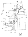
- fig. 1 shows a diagrammatical illustration of a preferred embodiment of the machine according to the invention, and
- fig. 2 shows an enlarged detail of a front portion of the machine shown in fig. 1.
- A combined laundry washing and drying machine according to the invention has an
outer housing 3 enclosing a tub 4 provided with acounterweight 5 and having afront opening 6 aligned with a front opening 7 ofhousing 3 and connected thereto by a bellows-type seal 8. - Mounted in tub 4 for rotation about a horizontal axis is a
drum 9 having a cylindricalouter wall 10 formed with through-openings 13, afront wall 11 and arear wall 12, as well as per se known and therefore not described ledge elements for entraining the laundry. -
Drum 9 is adapted to be rotated by an electric motor and a per se known and therefore not shown belt transmission, and is formed with a front loading opening 14 aligned withfront openings housing 3, respectively. - Front opening 7 of
housing 3 is provided with adoor 15 made of a transparent material such as glass or plastics and hinged tohousing 3. - Laundering tub 4 has a bottom opening 16 connected via a
conduit 17 and afiltering device 18 to adischarge pump 19 and aconduit 20 for discharging the washing liquid from the machine at the end of the washing and rinsing cycles. The machine according to the invention is adapted to carry out in a per se known manner a laundering process by immersion of the laundry, or a washing process by spraying the laundry with a reduced amount of a continuously recirculated washing liquid. - To this
purpose filtering device 18 is connected via aconduit 21, a collectingreceptacle 22 and arecirculation pump 23 to aconduit 24 extending through a top wall of tub 4 for spraying the laundry contained indrum 9 with jets of the washing liquid. - The machine according to the invention also includes a forced air-flow drying system in which heated air is caused to flow through
drum 9 with the moist laundry contained therein, the air being subsequently dehumidified and recirculated. - To this purpose there is provided a
fan 25 having its intake connected to arear opening 26 of tub 4 via a water-cooledcondenser device 27, the outlet side offan 25 being connected to a top opening 28 of tub 4 via aconduit 29 containing electricresistance heater elements 30. -
Condenser device 27 is of a known type and connected via aconduit 31 and asolenoid valve 32 to the water supply mains for supplying the water required forcooling condenser device 27 viaconduit 31 and an associatedspray nozzle 33. - The heated drying air exiting from top opening 28 of tub 4 is subsequently directed towards
drum 9 for entraining the moisture from the laundry contained therein. - According to the invention, the flow path of the heated drying air exiting from opening 28 is not defined as in known machines by hermetically sealed conduit means, but is advantageously established by a suitable design of already existing components immediately required for the operation of the machine.
- As shown in fig. 2, a
first deflector lip 34 of adequate rigidity is integrally formed with aseal 35 disposed betweenconduit 29 and tub 4 so as to deflect the hot air flow towards thefront wall 36 of tub 4 as indicated by arrows. - At this
location front wall 36 of tub 4 is formed with arecess 37 adapted to receive the hot air provenient fromdeflector lip 34 and to direct a first hot air flow towardsfront wall 11 ofdrum 9 suitably formed with through-openings 38. - The hot drying air bypassing openings 38 approaches the upper boundary of front opening 14 of
drum 9 and is deflected intodrum 9 by asecond deflector lip 39 of adequate rigidity integrally formed with the upper half of bellows-type seal 8. -
Second deflector lip 39 thus directs a second hot air flow towards the center of the laundry charge contained indrum 9. - The advantages arising from the shape and positioning of
second deflector lip 39 are mainly due to the fact that the hot air flow deflected thereby is capable of diffusing in the interior ofdrum 9 so as to sweep the greatest possible surface area of the laundry, and not only a small proportion thereof. -
Second deflector lip 39 has the further advantageous effect of protecting bellows-type seal 8 anddoor 15 from direct contact with the hot air, so that specificallydoor 15 is prevented from becoming heated to a temperature at which the laundry might be singed or the user might sustain burns on contact therewith. -
Deflector lips front wall 36 of tub 4, or even by the employ of separate components. - In the course of laboratory tests it has been found that the provision of deflector means 34, 37 and 39 and the elimination of hermetically sealed hot air conduit means permit the overall efficiency of the machine during the drying process to be optimized.
- As a matter of fact, not all of the hot air exiting from opening 28 is received by
recess 37 andsecond deflector lip 39, part of it being permitted to diffuse between tub 4 anddrum 9 to thereby establish a unifoem temperature within tub 4 and thus within the laundry charge. - The hot air flows deflected by
recess 37 anddeflector lip 39 are directly received by the moist laundry charge to result in a successive movement of the hot and moist air from the interior to the exterior ofdrum 9. - In the machine according to the invention, the indispensable conditions are thus established for obtaining a good result of the drying process, by ensuring that the hot air sweeps the greatest possible surface area of the laundry and the hot and moist air is caused to move from the interior to the exterior of
drum 9. - It is to be noted that the program of laundry washing and drying machines operating on the recirculation principle including spraying the laundry with the washing liquid provides for the execution of one or more spin-drying steps during the washing cycle. This may lead to the formation of substantial amounts of foam capable of entering and thereby obturating the drying air supply conduit.
- A further advantageous aspect of the machine according to the invention is therefore the provision of an anti-foam feature obtained by suitable subdividing the output of recirculation conduit 24 (fig. 1).
- In particular,
recirculation conduit 24 is provided with a first and asecond soray nozzle cylindrical wall 10 ofdrum 9 and towards hot air entrance opening 28, respectively. -
First nozzle 40 is effective in a per se known manner to spray the washing liquid onto the laundry throughperforations 13 ofdrum 9, whilesecond nozzle 41 acts to abate the foam formed during the spin-drying steps for maintaining the hot air supply passage betweendrum 9 and tub 4 free of obturation. - The described laundry washing and drying machine may of course be provided with any of the operating and control elements (program control unit, thermostats, pressure switches etc.) usually employed in machines of this type and therefore not requiring any specific description. The machine according to the invention may also be modified, be it with regard to the arrangement of its functional elements, such as
fan 25 orcondenser 27, or with regard to the construction of the drying circuit, which may be of the condenser-equipped closed type or of the ambient-air open type, without thereby leaving the scope of protection of the characteristics described and claimed.
Claims (3)
Applications Claiming Priority (2)
| Application Number | Priority Date | Filing Date | Title |
|---|---|---|---|
| IT4573686 | 1986-07-11 | ||
| IT45736/86A IT1201780B (en) | 1986-07-11 | 1986-07-11 | COMBINED MACHINE FOR LAUNDRY WASHING AND DRYING |
Publications (3)
| Publication Number | Publication Date |
|---|---|
| EP0252323A2 true EP0252323A2 (en) | 1988-01-13 |
| EP0252323A3 EP0252323A3 (en) | 1988-07-06 |
| EP0252323B1 EP0252323B1 (en) | 1991-03-20 |
Family
ID=11257918
Family Applications (1)
| Application Number | Title | Priority Date | Filing Date |
|---|---|---|---|
| EP87108385A Expired - Lifetime EP0252323B1 (en) | 1986-07-11 | 1987-06-10 | Combined laundry washing and drying machine |
Country Status (4)
| Country | Link |
|---|---|
| EP (1) | EP0252323B1 (en) |
| DE (1) | DE3768722D1 (en) |
| ES (1) | ES2020963B3 (en) |
| IT (1) | IT1201780B (en) |
Cited By (18)
| Publication number | Priority date | Publication date | Assignee | Title |
|---|---|---|---|---|
| EP0344549A1 (en) * | 1988-05-30 | 1989-12-06 | INDUSTRIE ZANUSSI S.p.A. | Heating apparatus for combined clothes washing and drying machine |
| EP0380992A1 (en) * | 1989-01-25 | 1990-08-08 | MERLONI ELETTRODOMESTICI S.p.A. | Improved clothes washing and drying appliance |
| EP0390011A1 (en) * | 1989-03-27 | 1990-10-03 | Hitachi, Ltd. | Dryer and washing/drying machine |
| EP0452678A3 (en) * | 1990-04-18 | 1992-07-22 | Zanussi Elettrodomestici S.P.A. | Control assembly for a combined laundry washing and drying machine |
| DE4104760A1 (en) * | 1991-02-15 | 1992-08-20 | Bosch Siemens Hausgeraete | DOMESTIC WASHING MACHINE FOR DRYING |
| EP1302586A1 (en) * | 2001-10-10 | 2003-04-16 | Electrolux Home Products Corporation N.V. | Combined clothes washing and drying machine |
| EP1544341A2 (en) | 2003-12-18 | 2005-06-22 | Lg Electronics Inc. | Washing machine with drying function |
| EP1688531A1 (en) * | 2005-02-03 | 2006-08-09 | Lg Electronics Inc. | Drum type washing and drying machine |
| EP2019164A1 (en) * | 2007-07-26 | 2009-01-28 | CANDY S.p.A. | Washer-drier machine |
| EP1925716A3 (en) * | 2006-11-21 | 2010-01-06 | Sanyo Electric Co., Ltd. | Laundry apparatus |
| CN1609326B (en) * | 2003-10-23 | 2010-04-28 | 松下电器产业株式会社 | Tumble Washer Dryer |
| EP2241663A1 (en) * | 2009-04-15 | 2010-10-20 | Electrolux Home Products Corporation N.V. | Washing-drying machine and method for operating the same |
| CN102535091A (en) * | 2010-10-21 | 2012-07-04 | 松下电器产业株式会社 | Laundry dryer and washing and drying machine |
| EP2570544A1 (en) * | 2011-09-15 | 2013-03-20 | Electrolux Home Products Corporation N.V. | Washing machine |
| DE102005018044C5 (en) * | 2004-04-19 | 2016-01-07 | Lg Electronics Inc. | Drum washing machine with laundry drying function |
| JP2018015252A (en) * | 2016-07-28 | 2018-02-01 | 日立アプライアンス株式会社 | Drum type washing machine |
| CN113981659A (en) * | 2021-11-16 | 2022-01-28 | 江苏海狮机械股份有限公司 | Sealing device in washing, drying and baking integrated machine |
| DE102022203313A1 (en) | 2022-04-04 | 2023-10-05 | BSH Hausgeräte GmbH | Laundry care device with a pump |
Families Citing this family (2)
| Publication number | Priority date | Publication date | Assignee | Title |
|---|---|---|---|---|
| CN107326620B (en) * | 2016-04-29 | 2020-04-24 | 青岛海尔滚筒洗衣机有限公司 | Washing machine window pad and washing machine |
| CN216107708U (en) * | 2021-09-09 | 2022-03-22 | 博西华电器(江苏)有限公司 | Drum washing and drying machine and door seal thereof |
Family Cites Families (5)
| Publication number | Priority date | Publication date | Assignee | Title |
|---|---|---|---|---|
| DE813843C (en) * | 1950-03-28 | 1951-09-17 | Poensgen A G Maschinenfabrik G | Drying device for laundry or the like. |
| US3006176A (en) * | 1960-06-03 | 1961-10-31 | Borg Warner | Combination washer-dryer |
| NL278336A (en) * | 1961-05-11 | |||
| DE1585675A1 (en) * | 1967-12-29 | 1970-12-03 | Constructa Werke Gmbh | Drum washing machine with drying device |
| DE2306873A1 (en) * | 1973-02-13 | 1974-08-22 | Licentia Gmbh | DRUM FOR LAUNDRY MACHINERY |
-
1986
- 1986-07-11 IT IT45736/86A patent/IT1201780B/en active
-
1987
- 1987-06-10 ES ES87108385T patent/ES2020963B3/en not_active Expired - Lifetime
- 1987-06-10 DE DE8787108385T patent/DE3768722D1/en not_active Expired - Fee Related
- 1987-06-10 EP EP87108385A patent/EP0252323B1/en not_active Expired - Lifetime
Cited By (29)
| Publication number | Priority date | Publication date | Assignee | Title |
|---|---|---|---|---|
| EP0344549A1 (en) * | 1988-05-30 | 1989-12-06 | INDUSTRIE ZANUSSI S.p.A. | Heating apparatus for combined clothes washing and drying machine |
| EP0380992A1 (en) * | 1989-01-25 | 1990-08-08 | MERLONI ELETTRODOMESTICI S.p.A. | Improved clothes washing and drying appliance |
| EP0390011A1 (en) * | 1989-03-27 | 1990-10-03 | Hitachi, Ltd. | Dryer and washing/drying machine |
| US5074131A (en) * | 1989-03-27 | 1991-12-24 | Hitachi, Ltd. | Dryer and washing/drying machine |
| EP0452678A3 (en) * | 1990-04-18 | 1992-07-22 | Zanussi Elettrodomestici S.P.A. | Control assembly for a combined laundry washing and drying machine |
| DE4104760A1 (en) * | 1991-02-15 | 1992-08-20 | Bosch Siemens Hausgeraete | DOMESTIC WASHING MACHINE FOR DRYING |
| EP1302586A1 (en) * | 2001-10-10 | 2003-04-16 | Electrolux Home Products Corporation N.V. | Combined clothes washing and drying machine |
| CN1609326B (en) * | 2003-10-23 | 2010-04-28 | 松下电器产业株式会社 | Tumble Washer Dryer |
| EP1544341A2 (en) | 2003-12-18 | 2005-06-22 | Lg Electronics Inc. | Washing machine with drying function |
| EP1544341A3 (en) * | 2003-12-18 | 2007-05-16 | Lg Electronics Inc. | Washing machine with drying function |
| DE102005018044C5 (en) * | 2004-04-19 | 2016-01-07 | Lg Electronics Inc. | Drum washing machine with laundry drying function |
| EP2290154A3 (en) * | 2005-02-03 | 2016-07-13 | LG Electronics Inc. | Drum type washing and drying machine |
| EP1688531A1 (en) * | 2005-02-03 | 2006-08-09 | Lg Electronics Inc. | Drum type washing and drying machine |
| EP3159449A1 (en) * | 2005-02-03 | 2017-04-26 | LG Electronics Inc. | Drum type washing and drying machine |
| US8166782B2 (en) | 2005-02-03 | 2012-05-01 | Lg Electronics Inc. | Drum type washing machine |
| US8186185B2 (en) | 2005-02-03 | 2012-05-29 | Lg Electronics Inc. | Drum type washing machine |
| US8201422B2 (en) | 2005-02-03 | 2012-06-19 | Lg Electronics Inc. | Drum type washing machine |
| EP2290153A3 (en) * | 2005-02-03 | 2016-07-13 | LG Electronics Inc. | Drum type washing and drying machine |
| EP1925716A3 (en) * | 2006-11-21 | 2010-01-06 | Sanyo Electric Co., Ltd. | Laundry apparatus |
| EP2019164A1 (en) * | 2007-07-26 | 2009-01-28 | CANDY S.p.A. | Washer-drier machine |
| EP2241663A1 (en) * | 2009-04-15 | 2010-10-20 | Electrolux Home Products Corporation N.V. | Washing-drying machine and method for operating the same |
| EP2444542A3 (en) * | 2010-10-21 | 2013-11-06 | Panasonic Corporation | Laundry dryer and washing and drying machine |
| CN102535091B (en) * | 2010-10-21 | 2015-04-15 | 松下电器产业株式会社 | washing and drying machine |
| CN102535091A (en) * | 2010-10-21 | 2012-07-04 | 松下电器产业株式会社 | Laundry dryer and washing and drying machine |
| EP2570544A1 (en) * | 2011-09-15 | 2013-03-20 | Electrolux Home Products Corporation N.V. | Washing machine |
| JP2018015252A (en) * | 2016-07-28 | 2018-02-01 | 日立アプライアンス株式会社 | Drum type washing machine |
| CN113981659A (en) * | 2021-11-16 | 2022-01-28 | 江苏海狮机械股份有限公司 | Sealing device in washing, drying and baking integrated machine |
| DE102022203313A1 (en) | 2022-04-04 | 2023-10-05 | BSH Hausgeräte GmbH | Laundry care device with a pump |
| EP4257740A1 (en) | 2022-04-04 | 2023-10-11 | BSH Hausgeräte GmbH | Laundry care appliance with a pump |
Also Published As
| Publication number | Publication date |
|---|---|
| ES2020963B3 (en) | 1991-10-16 |
| EP0252323B1 (en) | 1991-03-20 |
| IT1201780B (en) | 1989-02-02 |
| DE3768722D1 (en) | 1991-04-25 |
| IT8645736A0 (en) | 1986-07-11 |
| EP0252323A3 (en) | 1988-07-06 |
Similar Documents
| Publication | Publication Date | Title |
|---|---|---|
| EP0252323B1 (en) | Combined laundry washing and drying machine | |
| US11512420B2 (en) | Washing machine and control method thereof | |
| EP1445367B1 (en) | Drying/washing machine | |
| US3876469A (en) | Dish-washer vent system | |
| JP3530091B2 (en) | Drum type washing machine | |
| US2957330A (en) | Combination washer and drier | |
| US2724905A (en) | Drying apparatus | |
| GB2253034A (en) | Cleaning the condenser in a laundry washer/drier | |
| MXPA06012871A (en) | Washing machine with a drying device. | |
| US6006445A (en) | Washer/dryer combination | |
| EP2634301B1 (en) | Household laundry washing and drying machine with a condensing device and method of operating this machine | |
| EP1544341B1 (en) | Washing machine with drying function | |
| CA1040418A (en) | Condenser apparatus | |
| US5718130A (en) | Washing/drying machine | |
| GB2172977A (en) | Washing machine with tumble dryer | |
| US2674249A (en) | Air flow controller for dishwashing and drying machines | |
| KR20180136773A (en) | Wall mounted drum type washing machine | |
| US2961863A (en) | Laundry machine, suds overflow control | |
| KR101223441B1 (en) | Drum type washing machine | |
| GB2215826A (en) | Laundry drier with droplet removal | |
| GB2172978A (en) | Tumbler dryers and washing machines | |
| EP0250870A2 (en) | Combined machine for washing and drying laundry | |
| US2807890A (en) | Laundry machine having improved temperature sensing means | |
| EP0752493A1 (en) | Laundry washing machine having washing liquid filtering means | |
| WO2023116852A1 (en) | Dehumidification device and dryer |
Legal Events
| Date | Code | Title | Description |
|---|---|---|---|
| PUAI | Public reference made under article 153(3) epc to a published international application that has entered the european phase |
Free format text: ORIGINAL CODE: 0009012 |
|
| AK | Designated contracting states |
Kind code of ref document: A2 Designated state(s): DE ES FR GB IT |
|
| PUAL | Search report despatched |
Free format text: ORIGINAL CODE: 0009013 |
|
| AK | Designated contracting states |
Kind code of ref document: A3 Designated state(s): DE ES FR GB IT |
|
| 17P | Request for examination filed |
Effective date: 19881019 |
|
| ITF | It: translation for a ep patent filed | ||
| 17Q | First examination report despatched |
Effective date: 19900507 |
|
| GRAA | (expected) grant |
Free format text: ORIGINAL CODE: 0009210 |
|
| AK | Designated contracting states |
Kind code of ref document: B1 Designated state(s): DE ES FR GB IT |
|
| ET | Fr: translation filed | ||
| REF | Corresponds to: |
Ref document number: 3768722 Country of ref document: DE Date of ref document: 19910425 |
|
| PLBE | No opposition filed within time limit |
Free format text: ORIGINAL CODE: 0009261 |
|
| STAA | Information on the status of an ep patent application or granted ep patent |
Free format text: STATUS: NO OPPOSITION FILED WITHIN TIME LIMIT |
|
| 26N | No opposition filed | ||
| PGFP | Annual fee paid to national office [announced via postgrant information from national office to epo] |
Ref country code: FR Payment date: 19990506 Year of fee payment: 13 |
|
| PGFP | Annual fee paid to national office [announced via postgrant information from national office to epo] |
Ref country code: GB Payment date: 19990517 Year of fee payment: 13 |
|
| PGFP | Annual fee paid to national office [announced via postgrant information from national office to epo] |
Ref country code: DE Payment date: 19990526 Year of fee payment: 13 |
|
| PGFP | Annual fee paid to national office [announced via postgrant information from national office to epo] |
Ref country code: ES Payment date: 19990604 Year of fee payment: 13 |
|
| PG25 | Lapsed in a contracting state [announced via postgrant information from national office to epo] |
Ref country code: GB Free format text: LAPSE BECAUSE OF NON-PAYMENT OF DUE FEES Effective date: 20000610 |
|
| PG25 | Lapsed in a contracting state [announced via postgrant information from national office to epo] |
Ref country code: ES Free format text: THE PATENT HAS BEEN ANNULLED BY A DECISION OF A NATIONAL AUTHORITY Effective date: 20000612 |
|
| GBPC | Gb: european patent ceased through non-payment of renewal fee |
Effective date: 20000610 |
|
| PG25 | Lapsed in a contracting state [announced via postgrant information from national office to epo] |
Ref country code: FR Free format text: LAPSE BECAUSE OF NON-PAYMENT OF DUE FEES Effective date: 20010228 |
|
| REG | Reference to a national code |
Ref country code: FR Ref legal event code: ST |
|
| PG25 | Lapsed in a contracting state [announced via postgrant information from national office to epo] |
Ref country code: DE Free format text: LAPSE BECAUSE OF NON-PAYMENT OF DUE FEES Effective date: 20010403 |
|
| REG | Reference to a national code |
Ref country code: ES Ref legal event code: FD2A Effective date: 20020204 |
|
| PG25 | Lapsed in a contracting state [announced via postgrant information from national office to epo] |
Ref country code: IT Free format text: LAPSE BECAUSE OF NON-PAYMENT OF DUE FEES Effective date: 20050610 |