EP0254500A1 - Improvements relating to cooking apparatus - Google Patents
Improvements relating to cooking apparatus Download PDFInfo
- Publication number
- EP0254500A1 EP0254500A1 EP87306344A EP87306344A EP0254500A1 EP 0254500 A1 EP0254500 A1 EP 0254500A1 EP 87306344 A EP87306344 A EP 87306344A EP 87306344 A EP87306344 A EP 87306344A EP 0254500 A1 EP0254500 A1 EP 0254500A1
- Authority
- EP
- European Patent Office
- Prior art keywords
- cooking
- back plate
- cavity
- cooking apparatus
- modules
- Prior art date
- Legal status (The legal status is an assumption and is not a legal conclusion. Google has not performed a legal analysis and makes no representation as to the accuracy of the status listed.)
- Withdrawn
Links
- 238000010411 cooking Methods 0.000 title claims abstract description 40
- 238000002360 preparation method Methods 0.000 claims abstract description 3
- 239000000463 material Substances 0.000 claims description 5
- 238000010438 heat treatment Methods 0.000 claims description 4
- 238000005485 electric heating Methods 0.000 claims description 2
- 229910052736 halogen Inorganic materials 0.000 claims description 2
- 150000002367 halogens Chemical class 0.000 claims description 2
- 239000010453 quartz Substances 0.000 claims description 2
- VYPSYNLAJGMNEJ-UHFFFAOYSA-N silicon dioxide Inorganic materials O=[Si]=O VYPSYNLAJGMNEJ-UHFFFAOYSA-N 0.000 claims description 2
- 230000008901 benefit Effects 0.000 abstract description 5
- 230000015556 catabolic process Effects 0.000 abstract 1
- 238000004519 manufacturing process Methods 0.000 description 12
- 238000005304 joining Methods 0.000 description 7
- 238000000034 method Methods 0.000 description 6
- 238000003466 welding Methods 0.000 description 4
- 238000010276 construction Methods 0.000 description 3
- 229910000831 Steel Inorganic materials 0.000 description 2
- 238000005452 bending Methods 0.000 description 2
- 238000003825 pressing Methods 0.000 description 2
- 230000002441 reversible effect Effects 0.000 description 2
- 238000004826 seaming Methods 0.000 description 2
- 239000010959 steel Substances 0.000 description 2
- 241000357293 Leptobrama muelleri Species 0.000 description 1
- 230000004308 accommodation Effects 0.000 description 1
- 239000000919 ceramic Substances 0.000 description 1
- 230000008859 change Effects 0.000 description 1
- 238000004140 cleaning Methods 0.000 description 1
- 230000000694 effects Effects 0.000 description 1
- 239000000446 fuel Substances 0.000 description 1
- 239000011521 glass Substances 0.000 description 1
- 230000008569 process Effects 0.000 description 1
- 230000004044 response Effects 0.000 description 1
- 229910001220 stainless steel Inorganic materials 0.000 description 1
- 239000010935 stainless steel Substances 0.000 description 1
Images


Classifications
-
- F—MECHANICAL ENGINEERING; LIGHTING; HEATING; WEAPONS; BLASTING
- F24—HEATING; RANGES; VENTILATING
- F24C—DOMESTIC STOVES OR RANGES ; DETAILS OF DOMESTIC STOVES OR RANGES, OF GENERAL APPLICATION
- F24C15/00—Details
- F24C15/08—Foundations or supports plates; Legs or pillars; Casings; Wheels
Definitions
- This invention relates to cooking apparatus and it relates in particular, to the construction of said cooking apparatus.
- a cooking apparatus consisting of one or more cavity modules fitted together as desired, each of said modules when fitted with appropriate cooking means, being capable of carrying out one or more functions associated with the preparation of foodstuffs and comprising frame means and a cavity wrap casing providing the sides, top and bottom of the arrangement, the said module being provided with means receptive to the attachment of a back plate thereto.
- each module includes frame means and a cavity wrap casing forming walls defining a cooking cavity, a back plate, cooking means supported on the back plate, means receptive to the attachment and detachment of the back plate, and a door affording access to the cavity.
- the components required to produce a particular type of oven for example, any one or more of: electric heating elements for an electric oven and/or grill; gas burners for a gas oven and/or grill; magnetron and wave guide for a microwave oven and a quartz halogen browning lamp for a browning foodstuff; fans and lights, are fitted to the back plate using attaching means; the back plate then being attached to the rear frame of the module.
- the back plate fitted with the desired components is preferably attached to the rear frame of the module towards the end of the assembly process.
- a power unit for a cooking appliance comprising a plate which carries heating means and which is adapted to be secured as an entity, to a cooking cavity of the appliance, the plate at least partially covering an aperture in said cavity.
- the front and rear frames of the modules are preferably identical; the bolt-holes on the rear frame may preferably be used to bolt on the aforementioned back plate and those on the front frame are preferably used for the attachment of a reversible left/right-handed door or a bottom hung door. It is further preferred that the said front and rear frames be made by pressing sheet material of enamelling grade.
- the oven cavity is formed by bending a sheet, preferably of a material suitable for enamelling, at four places and joining the two ends together.
- the joint may be made by welding, lock seaming or by any other jointing technique known in the art. It is also preferred that a flange is thrown up around either end of the cavity wrap. This facilitates the joining of the end frames to the cavity wrap, which is preferably done by spot welding, lock seaming, stitching or any other joining means known in the art.
- the modules are enamelled after assembly, but before the back plates are fitted.
- the back plates themselves may preferably, though not necessarily be enamelled or painted after the holes, via which the cooking components are fitted, are punched.
- the back plates are then bolted to the rear frame of the module.
- the back plate is welded to the frame before being coated, in order to achieve electrical continuity.
- Figure 1 shows how the module of the invention is constructed with front and rear frames 1 and 2 respectively, formed from pressed steel.
- the front and rear frames 1 and 2 are identical, with identical bolt-holes for the attachment of reversible left/right-handed door and a back plate (not shown) respectively and with inwardly projecting flanges 1A and 2A.
- the back plate can be fixed to either frame.
- the assembly can be turned around and the back plate attached to the front frame 1.
- frames 1 and 2 are identical, they can be produced on the same production lines without necessitating a change of tooling.
- the front and rear frames 1 and 2 are attached to a cavity wrap 3, which is formed by bending typically a 0.4 or 0.9mm thick sheet of enamelling grade material at four places 4 and joining the two ends together to form a seam 5.
- the seam 5 is lockseamed, stitched or spot welded, or joined by any other suitable jointing technique known in the art.
- the cavity 3 is also provided with flanges 6 to facilitate the joining of the end frames 1 and 2 to the cavity wrap 3.
- the end frames 1 and 2 are joined to the cavity wrap 3, via flanges 6, by spot welding, stitching, lockseaming or any other joining technique known in the art.
- spot welding stitching, lockseaming or any other joining technique known in the art.
- the end frames 1 and 2 instead of the cavity wrap 3 are provided with flanges.
- the back plates are of three basic types; gas, electric and microwave and are produced at a sub-assembly line sited towards the end of the main assembly line in order to fix the specification of a cooker as late as possible in the production process.
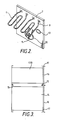
- FIG. 2 A specific embodiment of a back plate, fitted with components, is shown in Figure 2 and comprises a steel back plate 7 with grill elements 8 and 9, another element 10 surrounding a fan 11, and with a light 12; these components are attached to the back plate 7 via holes (not shown) punched in the back plate 7.
- the back plate 7 is preferably enamelled or painted after the holes have been punched, and before the components are fitted.
- the back plate 7 is not enamelled or painted until it has been attached, with components in place, to the rear frame 2 of a module, in order to ensure electrical continuity.
- the back plate 7 is normally welded or forms part of the rear of the oven cavity or cavity assembly, then it is all enamelled and then the components for that particular oven are fitted, this means that many different assembly lines are needed, or disruptions to assembly lines whilst model changes are effected.
- the back plates 7 are not fitted until near the end of the assembly line, thus cooker model and specification are not fixed until the end of assembly line and so all models run down the same line and no tooling changes are required for a large number of models of varying size, specification and fuel type.
- a second advantage of the present invention over the prior art is that the components, that is heating elements etc and associated wiring, are fitted to the back plate 7 before the back plate 7 is fitted to the module, hence working access is much freer and consequently assembly time much reduced.
- Another advantage of the present invention over the prior art is that the components, that is heating elements etc., fitted to the back plates 7 can be tested before the back plate 7 is fitted to the module; conventionally they are tested after fitting in the oven cavity, which can be problematic if any faults arise. Over all the present invention reduces production costs considerably.
- Figure 3 shows a side-on vertical cross-section of a small cavity module 13 and a larger cavity module 14, joined together by bolted joints 15 and with their back plates 16, fitted with components, already in place.
- the back plates 16 having been attached to the end frames 17 by bolting with rivets or screws (not shown) or by welding.
- Figure 4 shows some of the wide variety of cookers that can be produced from just two sizes of module by varying the components fitted to the back plate and by combining and configuring the modules in different ways.
- Figure 4(a) is of a single small module and could be used for:- a microwave or a table top oven with grill 18, the completed appliance being approximately 300mm in height.
- Figure 4(b) is of a single large module and could be used for a main oven with a grill 19, the completed appliance being nominally 600mm in height.
- Figure 4(c) is of two small modules mounted one above the other and could be used for a microwave 20 combined with a small oven with grill 21 and the completed appliance is nominally 600mm in height.
- Figure 4(d) is of a large module mounted above a small module and could be used for either a main oven 22 and a second small oven with a grill 23 or a main oven 22 and grill 23 for use as built in cookers, nominally 900mm in height or a free-standing main oven 22 with a warm drawer 23, and the completed appliances, including hob, would be nominally either 850 or 900mm in height depending on dimensions of plinth and feet.
- Figure 4(e) can be a free standing main oven 24 and a second oven with a grill 25 or a free-standing main oven 24 and grill only 25.
- the overall height of the completed appliance including a hob can be 850mm or 900mm depending on dimensions of plinth and feet.
- Figure 4(f) shows two large modules mounted one above the other and could be used for a double oven comprising two large ovens 26 and 27, the completed appliance being nominally 1200mm in height.
- Figure 4(g) shows two small modules mounted above a large module and could be used for a main oven 28, second oven with grill 29 and a microwave 30, the completed appliance being nominally 1200mm in height.
- three widths of cooker can be provided; 500, 550 and 600mm being the most desirable widths.
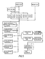
- Figure 5 shows a schematic layout of a possible production line, which utilizes the invention's method of assembly.
- oven cavity and back plate are described as being preferably made from steel, they could equally well be made from stainless steel, glass, ceramic or any other suitable material. It is also likely that popular combinations of modules could justify special front and back frames, to accommodate a plurality of modules in accordance with the relevant combination. If desired either one of the front and rear frame may be omitted. A thermal break may be provided between the front frame and the cavity wrap to allow for a high temperature self-cleaning construction.
- the cooking apparatus of this invention makes it possible to produce a wide range of cookers that will satisfy most, if not all, of the market demands, from only two basic modules plus a variety of back plates and, because the model and specifications are not fixed until the end of the production process, all the models can be produced on one assembly line without tooling changes, resulting in a cheaper and simpler manufacturing process.
- a further advantage of the invention lies in the possibility of adapting quickly to unforseen changes in market requirements as the core construction, that is the modules, will be common to existing production. Limited changes, for example to configuration, accommodation on back plates of novel energy inputting devices or other innovative components and facia, are sufficient to produce a new appliance. This results in faster response to the manufacturer to changing trends and lower costs of changed production equipment.
Landscapes
- Engineering & Computer Science (AREA)
- Chemical & Material Sciences (AREA)
- Combustion & Propulsion (AREA)
- Mechanical Engineering (AREA)
- General Engineering & Computer Science (AREA)
- Electric Ovens (AREA)
- Electric Stoves And Ranges (AREA)
Abstract
Description
- This invention relates to cooking apparatus and it relates in particular, to the construction of said cooking apparatus.
- At present there exists a wide variety of cooking apparatus, for example ovens, grills, combined over/grills and microwaves, manufactured to a wide variety of specifications and designs differently fuelled and, consequently, requiring many different assembly lines for their production.
- It is an object of the present invention to produce a large number of variants of cooking apparatus from only a few basic modular units, by combining these units in different ways.
- According to the present invention there is provided a cooking apparatus consisting of one or more cavity modules fitted together as desired, each of said modules when fitted with appropriate cooking means, being capable of carrying out one or more functions associated with the preparation of foodstuffs and comprising frame means and a cavity wrap casing providing the sides, top and bottom of the arrangement, the said module being provided with means receptive to the attachment of a back plate thereto.
- According to another form of the invention, each module includes frame means and a cavity wrap casing forming walls defining a cooking cavity, a back plate, cooking means supported on the back plate, means receptive to the attachment and detachment of the back plate, and a door affording access to the cavity.
- In a preferred embodiment of the invention the components required to produce a particular type of oven, for example, any one or more of: electric heating elements for an electric oven and/or grill; gas burners for a gas oven and/or grill; magnetron and wave guide for a microwave oven and a quartz halogen browning lamp for a browning foodstuff; fans and lights, are fitted to the back plate using attaching means; the back plate then being attached to the rear frame of the module. The back plate fitted with the desired components is preferably attached to the rear frame of the module towards the end of the assembly process.
- According to a further aspect of the invention there is provided a power unit for a cooking appliance, the power unit comprising a plate which carries heating means and which is adapted to be secured as an entity, to a cooking cavity of the appliance, the plate at least partially covering an aperture in said cavity.
- The front and rear frames of the modules are preferably identical; the bolt-holes on the rear frame may preferably be used to bolt on the aforementioned back plate and those on the front frame are preferably used for the attachment of a reversible left/right-handed door or a bottom hung door. It is further preferred that the said front and rear frames be made by pressing sheet material of enamelling grade.
- In a preferred embodiment of the invention the oven cavity is formed by bending a sheet, preferably of a material suitable for enamelling, at four places and joining the two ends together. The joint may be made by welding, lock seaming or by any other jointing technique known in the art. It is also preferred that a flange is thrown up around either end of the cavity wrap. This facilitates the joining of the end frames to the cavity wrap, which is preferably done by spot welding, lock seaming, stitching or any other joining means known in the art.
- In a further preferred embodiment of the invention the modules are enamelled after assembly, but before the back plates are fitted. In the cases of electric or gas ovens the back plates themselves may preferably, though not necessarily be enamelled or painted after the holes, via which the cooking components are fitted, are punched. The back plates are then bolted to the rear frame of the module. For microwave ovens the back plate is welded to the frame before being coated, in order to achieve electrical continuity.
- It is a preferred embodiment of this invention that only two sizes of cavity module are made (preferably one large, one small) which, when each is fitted with the various desired arrangement of cooking components, are combined in a variety of ways to produce a range of cookers which will satisfy most of the market demands.
- In order that the invention may be clearly understood and readily carried into effect, specific embodiments of the invention will now be described by way of example, with reference to the accompanying drawings, of which
- Figure 1 is a perspective view of the invention, showing how the cavity module is constructed,
- Figure 2 shows a perspective view of a specific embodiment of said further aspect of the invention,
- Figure 3 is a side on vertical cross-section of a particular application of the invention,
- Figure 4 shows, in vertical cross-section, various ways of combining the modular units of the invention,
- Figure 5, is a schematic layout of a possible production line for the invention.
- Figure 1 shows how the module of the invention is constructed with front and rear frames 1 and 2 respectively, formed from pressed steel. The front and rear frames 1 and 2 are identical, with identical bolt-holes for the attachment of reversible left/right-handed door and a back plate (not shown) respectively and with inwardly projecting
flanges - The front and rear frames 1 and 2 are attached to a cavity wrap 3, which is formed by bending typically a 0.4 or 0.9mm thick sheet of enamelling grade material at four places 4 and joining the two ends together to form a
seam 5. Theseam 5 is lockseamed, stitched or spot welded, or joined by any other suitable jointing technique known in the art. The cavity 3 is also provided withflanges 6 to facilitate the joining of the end frames 1 and 2 to the cavity wrap 3. The end frames 1 and 2 are joined to the cavity wrap 3, viaflanges 6, by spot welding, stitching, lockseaming or any other joining technique known in the art. Thus forming an inherently strong mechanically stiff component. After fabrication the modules are enamelled and are ready to have the back plates (not shown) fitted. Up to this point all modules are produced on the one component line, since the type of cooker for which any individual module is intended is not decided until the back plate, fitted with the desired components, is attached. As an alternative jointing arrangement, which may be preferred in some circumstances, the end frames 1 and 2, instead of the cavity wrap 3 are provided with flanges. - The back plates are of three basic types; gas, electric and microwave and are produced at a sub-assembly line sited towards the end of the main assembly line in order to fix the specification of a cooker as late as possible in the production process.
- A specific embodiment of a back plate, fitted with components, is shown in Figure 2 and comprises a steel back plate 7 with
grill elements 8 and 9, anotherelement 10 surrounding afan 11, and with alight 12; these components are attached to the back plate 7 via holes (not shown) punched in the back plate 7. In the cases of gas and electric ovens the back plate 7 is preferably enamelled or painted after the holes have been punched, and before the components are fitted. However, for microwave ovens the back plate 7 is not enamelled or painted until it has been attached, with components in place, to the rear frame 2 of a module, in order to ensure electrical continuity. - In conventional ovens the back plate 7 is normally welded or forms part of the rear of the oven cavity or cavity assembly, then it is all enamelled and then the components for that particular oven are fitted, this means that many different assembly lines are needed, or disruptions to assembly lines whilst model changes are effected.
- In the case of the present invention the back plates 7 are not fitted until near the end of the assembly line, thus cooker model and specification are not fixed until the end of assembly line and so all models run down the same line and no tooling changes are required for a large number of models of varying size, specification and fuel type. A second advantage of the present invention over the prior art is that the components, that is heating elements etc and associated wiring, are fitted to the back plate 7 before the back plate 7 is fitted to the module, hence working access is much freer and consequently assembly time much reduced. Another advantage of the present invention over the prior art is that the components, that is heating elements etc., fitted to the back plates 7 can be tested before the back plate 7 is fitted to the module; conventionally they are tested after fitting in the oven cavity, which can be problematic if any faults arise. Over all the present invention reduces production costs considerably.
- As well as providing a variety of ovens from one basic module by fitting various different back plates 7, it is also possible to extend the range yet further by joining modules together.
- Figure 3 shows a side-on vertical cross-section of a small cavity module 13 and a
larger cavity module 14, joined together by boltedjoints 15 and with theirback plates 16, fitted with components, already in place. Theback plates 16 having been attached to theend frames 17 by bolting with rivets or screws (not shown) or by welding. Thus, since the modules from which the cooker core is formed are strong and mechanically stiff, so are combinations of said modules. - Figure 4 shows some of the wide variety of cookers that can be produced from just two sizes of module by varying the components fitted to the back plate and by combining and configuring the modules in different ways.
- Figure 4(a) is of a single small module and could be used for:- a microwave or a table top oven with
grill 18, the completed appliance being approximately 300mm in height. Figure 4(b) is of a single large module and could be used for a main oven with agrill 19, the completed appliance being nominally 600mm in height. Figure 4(c) is of two small modules mounted one above the other and could be used for amicrowave 20 combined with a small oven withgrill 21 and the completed appliance is nominally 600mm in height. Figure 4(d) is of a large module mounted above a small module and could be used for either amain oven 22 and a second small oven with agrill 23 or amain oven 22 andgrill 23 for use as built in cookers, nominally 900mm in height or a free-standingmain oven 22 with awarm drawer 23, and the completed appliances, including hob, would be nominally either 850 or 900mm in height depending on dimensions of plinth and feet. Figure 4(e) can be a free standingmain oven 24 and a second oven with agrill 25 or a free-standingmain oven 24 and grill only 25. The overall height of the completed appliance including a hob can be 850mm or 900mm depending on dimensions of plinth and feet. Figure 4(f) shows two large modules mounted one above the other and could be used for a double oven comprising twolarge ovens main oven 28, second oven withgrill 29 and amicrowave 30, the completed appliance being nominally 1200mm in height. In addition, by appropriate cooker design three widths of cooker can be provided; 500, 550 and 600mm being the most desirable widths. - Figure 5 shows a schematic layout of a possible production line, which utilizes the invention's method of assembly.
- Other possible embodiments of the invention are, for example, a small electric oven with a single flat element attached to the back plate and a small table top oven with a hob on top. Also, although the oven cavity and back plate are described as being preferably made from steel, they could equally well be made from stainless steel, glass, ceramic or any other suitable material. It is also likely that popular combinations of modules could justify special front and back frames, to accommodate a plurality of modules in accordance with the relevant combination. If desired either one of the front and rear frame may be omitted. A thermal break may be provided between the front frame and the cavity wrap to allow for a high temperature self-cleaning construction.
- It should also be noted that, in the case of a microwave oven, it is not necessary to weld the back plate to the oven cavity provided the quarter wave choke technique is used with bolting, or other configurations of pressings, to prevent microwave leakage.
- Thus, the cooking apparatus of this invention makes it possible to produce a wide range of cookers that will satisfy most, if not all, of the market demands, from only two basic modules plus a variety of back plates and, because the model and specifications are not fixed until the end of the production process, all the models can be produced on one assembly line without tooling changes, resulting in a cheaper and simpler manufacturing process. A further advantage of the invention lies in the possibility of adapting quickly to unforseen changes in market requirements as the core construction, that is the modules, will be common to existing production. Limited changes, for example to configuration, accommodation on back plates of novel energy inputting devices or other innovative components and facia, are sufficient to produce a new appliance. This results in faster response to the manufacturer to changing trends and lower costs of changed production equipment.
Claims (10)
electric heating elements for an electric oven and/or grill; gas burners for a gas oven and/or grill; magnetron and wave guide for a microwave oven and a quartz halogen browning lamp for a browning foodstuff.
Applications Claiming Priority (2)
| Application Number | Priority Date | Filing Date | Title |
|---|---|---|---|
| GB868617773A GB8617773D0 (en) | 1986-07-21 | 1986-07-21 | Cooking apparatus |
| GB8617773 | 1986-07-21 |
Publications (1)
| Publication Number | Publication Date |
|---|---|
| EP0254500A1 true EP0254500A1 (en) | 1988-01-27 |
Family
ID=10601433
Family Applications (1)
| Application Number | Title | Priority Date | Filing Date |
|---|---|---|---|
| EP87306344A Withdrawn EP0254500A1 (en) | 1986-07-21 | 1987-07-17 | Improvements relating to cooking apparatus |
Country Status (4)
| Country | Link |
|---|---|
| EP (1) | EP0254500A1 (en) |
| JP (1) | JPS6488034A (en) |
| AU (1) | AU7591487A (en) |
| GB (1) | GB8617773D0 (en) |
Cited By (11)
| Publication number | Priority date | Publication date | Assignee | Title |
|---|---|---|---|---|
| WO2003054449A1 (en) * | 2001-12-21 | 2003-07-03 | BSH Bosch und Siemens Hausgeräte GmbH | Cooking device muffle and a method for the production of a cooking device muffle |
| ES2215425A1 (en) * | 2001-02-15 | 2004-10-01 | Lackey, S.A. | Furnace body e.g. oven body, has plate provided with envelope unit that folds hearth, side walls and vault part of firing chamber, where ends of envelope unit is fixed and laminated with rear part of enamel body by welding part |
| EP1764560A1 (en) * | 2005-09-15 | 2007-03-21 | Whirlpool Corporation | Domestic oven |
| WO2007147867A3 (en) * | 2006-06-21 | 2008-06-12 | Arcelik As | An oven |
| WO2008064992A3 (en) * | 2006-11-30 | 2008-07-31 | Bsh Bosch Siemens Hausgeraete | Domestic appliance wall arrangement and method for fixing wall parts in a domestic appliance |
| WO2010029088A1 (en) * | 2008-09-12 | 2010-03-18 | Arcelik Anonim Sirketi | An oven casing assembly |
| ITPD20100003A1 (en) * | 2010-01-14 | 2011-07-15 | Unox Spa | COOKING OVEN FOR FOOD, IN PARTICULAR FOR COLLECTIVITY SERVICES |
| EP2840321A1 (en) * | 2013-08-19 | 2015-02-25 | Electrolux Appliances Aktiebolag | Oven muffle for a domestic oven |
| IT201700088481A1 (en) * | 2017-08-01 | 2019-02-01 | Dometic Sweden Ab | MODULAR KITCHEN FOR RECREATIONAL VEHICLE AND ITS MANUFACTURING METHOD |
| CN112914348A (en) * | 2021-03-01 | 2021-06-08 | 广东美的厨房电器制造有限公司 | Cooking device |
| CN112954840A (en) * | 2021-03-01 | 2021-06-11 | 广东美的厨房电器制造有限公司 | Cooking device |
Citations (3)
| Publication number | Priority date | Publication date | Assignee | Title |
|---|---|---|---|---|
| US1586158A (en) * | 1926-01-06 | 1926-05-25 | Moore Company Ltd D | Oven for electric ranges |
| US3033188A (en) * | 1958-08-08 | 1962-05-08 | Sears Roebuck & Co | Cooking range |
| GB2107160A (en) * | 1981-06-16 | 1983-04-20 | Sharp Kk | Microwave ovens |
-
1986
- 1986-07-21 GB GB868617773A patent/GB8617773D0/en active Pending
-
1987
- 1987-07-17 EP EP87306344A patent/EP0254500A1/en not_active Withdrawn
- 1987-07-20 AU AU75914/87A patent/AU7591487A/en not_active Abandoned
- 1987-07-21 JP JP18210287A patent/JPS6488034A/en active Pending
Patent Citations (3)
| Publication number | Priority date | Publication date | Assignee | Title |
|---|---|---|---|---|
| US1586158A (en) * | 1926-01-06 | 1926-05-25 | Moore Company Ltd D | Oven for electric ranges |
| US3033188A (en) * | 1958-08-08 | 1962-05-08 | Sears Roebuck & Co | Cooking range |
| GB2107160A (en) * | 1981-06-16 | 1983-04-20 | Sharp Kk | Microwave ovens |
Cited By (13)
| Publication number | Priority date | Publication date | Assignee | Title |
|---|---|---|---|---|
| ES2215425A1 (en) * | 2001-02-15 | 2004-10-01 | Lackey, S.A. | Furnace body e.g. oven body, has plate provided with envelope unit that folds hearth, side walls and vault part of firing chamber, where ends of envelope unit is fixed and laminated with rear part of enamel body by welding part |
| WO2003054449A1 (en) * | 2001-12-21 | 2003-07-03 | BSH Bosch und Siemens Hausgeräte GmbH | Cooking device muffle and a method for the production of a cooking device muffle |
| EP1764560A1 (en) * | 2005-09-15 | 2007-03-21 | Whirlpool Corporation | Domestic oven |
| WO2007147867A3 (en) * | 2006-06-21 | 2008-06-12 | Arcelik As | An oven |
| WO2008064992A3 (en) * | 2006-11-30 | 2008-07-31 | Bsh Bosch Siemens Hausgeraete | Domestic appliance wall arrangement and method for fixing wall parts in a domestic appliance |
| WO2010029088A1 (en) * | 2008-09-12 | 2010-03-18 | Arcelik Anonim Sirketi | An oven casing assembly |
| ITPD20100003A1 (en) * | 2010-01-14 | 2011-07-15 | Unox Spa | COOKING OVEN FOR FOOD, IN PARTICULAR FOR COLLECTIVITY SERVICES |
| EP2840321A1 (en) * | 2013-08-19 | 2015-02-25 | Electrolux Appliances Aktiebolag | Oven muffle for a domestic oven |
| IT201700088481A1 (en) * | 2017-08-01 | 2019-02-01 | Dometic Sweden Ab | MODULAR KITCHEN FOR RECREATIONAL VEHICLE AND ITS MANUFACTURING METHOD |
| EP3438548A1 (en) | 2017-08-01 | 2019-02-06 | Dometic Sweden AB | Modular cooker for recreational vehicle and method for manufacturing it |
| CN112914348A (en) * | 2021-03-01 | 2021-06-08 | 广东美的厨房电器制造有限公司 | Cooking device |
| CN112954840A (en) * | 2021-03-01 | 2021-06-11 | 广东美的厨房电器制造有限公司 | Cooking device |
| CN112954840B (en) * | 2021-03-01 | 2023-11-03 | 广东美的厨房电器制造有限公司 | cooking device |
Also Published As
| Publication number | Publication date |
|---|---|
| GB8617773D0 (en) | 1986-08-28 |
| AU7591487A (en) | 1988-01-28 |
| JPS6488034A (en) | 1989-04-03 |
Similar Documents
| Publication | Publication Date | Title |
|---|---|---|
| US5190026A (en) | Modular countertop cooking system | |
| EP0254500A1 (en) | Improvements relating to cooking apparatus | |
| EP0429822B1 (en) | Combined microwave and forced convection oven | |
| US5886330A (en) | Microwave oven having filtered air exhaust passages | |
| JPS6135847Y2 (en) | ||
| CN108236354A (en) | A kind of steam box oven microwave oven all-in-one machine | |
| KR20070108022A (en) | Heating device and cooking apparatus including the same | |
| EP4148329B1 (en) | Cooking appliance and a method of operating the cooking appliance | |
| CA2319278C (en) | Microwave oven | |
| US4609801A (en) | Cavity construction for microwave oven | |
| GB2197457A (en) | Cooking appliances | |
| EP0573750B1 (en) | Microwave oven | |
| CN100422647C (en) | High frequency heating device | |
| RU2175467C2 (en) | Magnetron oven with heater | |
| NL8303532A (en) | HIGH-FREQUENT HEATING DEVICE. | |
| JP2002228156A (en) | Electrical component chamber structure of microwave oven | |
| EP1445986B1 (en) | Microwave oven, more particularly oven which barbecues food | |
| US3257543A (en) | Combination oven and surface unit | |
| AU2006295058B2 (en) | Control cabinets for food processing systems | |
| US7547864B2 (en) | Microwave oven having plural magnetrons with cooling air flow | |
| EP1560464B1 (en) | Wall-mounted microwave oven | |
| JPH0438161Y2 (en) | ||
| CN222718247U (en) | Integrated kitchen range | |
| CN216147866U (en) | Cavity structure for containing cooking food materials and cooking equipment | |
| KR19990039540A (en) | Cabinet assembly of microwave oven |
Legal Events
| Date | Code | Title | Description |
|---|---|---|---|
| PUAI | Public reference made under article 153(3) epc to a published international application that has entered the european phase |
Free format text: ORIGINAL CODE: 0009012 |
|
| AK | Designated contracting states |
Kind code of ref document: A1 Designated state(s): AT BE CH DE ES FR GB GR IT LI LU NL SE |
|
| 17P | Request for examination filed |
Effective date: 19880317 |
|
| 17Q | First examination report despatched |
Effective date: 19890420 |
|
| STAA | Information on the status of an ep patent application or granted ep patent |
Free format text: STATUS: THE APPLICATION IS DEEMED TO BE WITHDRAWN |
|
| 18D | Application deemed to be withdrawn |
Effective date: 19891003 |
|
| RIN1 | Information on inventor provided before grant (corrected) |
Inventor name: WATROBA, DAVID BRIAN Inventor name: CROSSLEY, PETER WILLIAM Inventor name: BROOKS, STEVE MARTIN Inventor name: BUTTERY, MICHAEL HARCOURT CHRISTIANS |