EP0258956A2 - Système commandé de la qualité d'un rayon d'un oscilloscope - Google Patents
Système commandé de la qualité d'un rayon d'un oscilloscope Download PDFInfo
- Publication number
- EP0258956A2 EP0258956A2 EP87301380A EP87301380A EP0258956A2 EP 0258956 A2 EP0258956 A2 EP 0258956A2 EP 87301380 A EP87301380 A EP 87301380A EP 87301380 A EP87301380 A EP 87301380A EP 0258956 A2 EP0258956 A2 EP 0258956A2
- Authority
- EP
- European Patent Office
- Prior art keywords
- trace
- attribute
- control data
- addresses
- count
- Prior art date
- Legal status (The legal status is an assumption and is not a legal conclusion. Google has not performed a legal analysis and makes no representation as to the accuracy of the status listed.)
- Withdrawn
Links
- 230000004044 response Effects 0.000 claims description 10
- 238000006073 displacement reaction Methods 0.000 claims 6
- 230000008859 change Effects 0.000 description 14
- 238000010894 electron beam technology Methods 0.000 description 6
- 229940000425 combination drug Drugs 0.000 description 4
- 238000010586 diagram Methods 0.000 description 2
- 238000012986 modification Methods 0.000 description 2
- 230000004048 modification Effects 0.000 description 2
- QHGVXILFMXYDRS-UHFFFAOYSA-N pyraclofos Chemical compound C1=C(OP(=O)(OCC)SCCC)C=NN1C1=CC=C(Cl)C=C1 QHGVXILFMXYDRS-UHFFFAOYSA-N 0.000 description 2
- 238000005070 sampling Methods 0.000 description 2
- OAICVXFJPJFONN-UHFFFAOYSA-N Phosphorus Chemical compound [P] OAICVXFJPJFONN-UHFFFAOYSA-N 0.000 description 1
- 238000007792 addition Methods 0.000 description 1
- 230000009286 beneficial effect Effects 0.000 description 1
- 230000000694 effects Effects 0.000 description 1
- 238000000034 method Methods 0.000 description 1
- 230000008520 organization Effects 0.000 description 1
- 238000012163 sequencing technique Methods 0.000 description 1
- 239000007787 solid Substances 0.000 description 1
Images
Classifications
-
- G—PHYSICS
- G01—MEASURING; TESTING
- G01R—MEASURING ELECTRIC VARIABLES; MEASURING MAGNETIC VARIABLES
- G01R13/00—Arrangements for displaying electric variables or waveforms
- G01R13/20—Cathode-ray oscilloscopes
- G01R13/22—Circuits therefor
- G01R13/28—Circuits for simultaneous or sequential presentation of more than one variable
Definitions
- the present invention relates in general to multiple trace oscilloscopes and in particular to an apparatus for controlling the attributes of each trace.
- the path of an electron beam across the screen of a cathode-ray tube appears as a "trace" of glowing phosphor on the screen.
- the "attributes" of a trace relate to its appearance on the screen including its shape and intensity, and determine signals which control the vertical and horizontal deflection of the electron beam as well as its intensity.
- a multiple trace oscilloscope a single electron beam creates multiple traces on a cathode-ray tube screen, each trace having different attribute combinations. For example when traces represent different oscilloscope input waveforms, the vertical deflection of the beam is responsive to different vertical input signals for each trace.
- the horizontal sweep of the beam may also be accomplished by different horizontal sweep signals for each trace so that different waveforms can be simultaneously displayed using different horizontal time scales. Different signals may furthermore be used to control the intensity of the beam for each trace so that some traces appear brighter than others
- the traces are periodically updated (refreshed) utilizing either an "alternating" mode or a "chop" mode of trace update.
- the oscilloscope updates one trace during each sweep of the beam across the screen so that several sweeps are required to update all of the traces once.
- the oscilloscope updates traces during each sweep by alternately updating sections of different traces as the beam sweeps once over the screen. Therefore when the chop mode is employed, each trace is actually "chopped," having horizontal gaps occurring during the times that the beam is updating other traces.
- the alternation in trace update occurs rapidly so that the gaps in each trace are small enough so each trace has a solid appearance.
- the oscilloscope selects attributes for each trace utilizing attribute control switches for selecting the appropriate signals to be transmitted to vertical, horizontal and "Z axis" amplifiers for controlling the vertical and horizontal deflection and the intensity of the electron beam. Prior to updating each trace, the oscilloscope adjusts the selections made by these attribute control switches to set the desired attributes for the trace.
- the attributes for each trace are predetermined by an operator utilizing knobs or push-buttons on the front panel of the oscilloscope which send signals indicating the attributes the operator wants for each trace to a state machine.
- the state machine has a number of output states, each corresponding to a different permissible trace attribute combination.
- the oscilloscope Each time the oscilloscope switches from updating one trace to updating a next trace, its sends a clock signal to the state machine causing the state machine to enter a next state determined according to the nature of the input signals from the front panel knobs or push buttons.
- the state machine output comprises a set of data bits which control the attribute control switches, causing them to select the appropriate vertical, horizontal and intensity control signals for the next trace to be updated.
- the state machine must have one state corresponding to each permissible combination of trace attributes.
- a trace attribute control state machine would require a prohibitively large number of states in order to permit any trace to have any possible combination of attributes. Since such a large state machine is impractical, multiple trace oscilloscopes permit only limited combinations of trace attributes for each trace. In addition, since the "next state" that a state machine enters is determined by the current state that it is in and by the input data provided during the current state, such state machines typically limit the order in which states can be entered and therefore limit the combinations of traces which can be displayed at the same time.
- a trace attribute controller for a multiple trace oscilloscope includes a random access memory (RAM) for storing, at separate addresses, trace attribute control data corresponding to each of multiple traces created by an electron beam traversing a cathode ray tube screen.
- a programmable counter counts a clock signal generated each time the beam updates a trace and addresses the RAM with its count output. The count indicates the next trace to be updated and when the RAM is addressed by the count, the RAM reads out the attribute control data corresponding to that trace.
- the attribute control data is then utilized to operate attribute control switches controlling attributes of the trace by selecting the appropriate signals controlling the vertical and horizontal deflection and the intensity of the beam as it updates the trace.
- the attributes of each trace may be independently determined and each trace may be assigned any possible combination of attributes by storing appropriate attribute control data in the RAM.
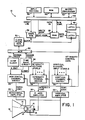
- oscilloscope 10 is adapted to display multiple traces on a cathode-ray tube (CRT) 12 screen wherein separate excursions of an electron beam across the CRT screen appear as separate "traces" on the screen.
- CRT cathode-ray tube
- the horizontal movement of the beam is controlled by a voltage applied across a pair of horizontal deflection plates 14 and the vertical motion of the beam is controlled by another voltage applied across a pair of vertical deflection plates 16.
- the intensity of the beam is controlled by a voltage applied to an electrode 18 in CRT 12.
- the voltage applied across the horizontal deflection plates 14 is generated by a horizontal amplifier 20 in response to an input horizontal control signal supplied by a horizontal channel switch 28.
- the horizontal channel switch selects the horizontal control signal supplied to the horizontal amplifier 20 from between "A" and "B" sweep signals generated by a time base circuit 30.
- the voltage applied across the vertical deflection plates 16 of the CRT 12 is generated by a vertical amplifier 22 in response to an input vertical control signal transmitted through a vertical channel switch 26.
- the vertical channel switch 26 selects the vertical control signal sent to amplifier 22 from among a plurality of vertical channel input signals, typically generated by a device under test (not shown).
- the voltage applied to the electrode 18 of CRT 12 for controlling beam intensity is produced by a "Z axis" amplifier 24 in response to an intensity control signal from an intensity channel switch 36 which selects the intensity control signal from among a plurality of input intensity control voltage levels.
- the multiple trace oscilloscope 10 periodically refreshes (updates) each trace in order to keep the trace visible on the CRT screen. Different traces are updated sequentially utilizing either an "alternating" mode or a "chop" mode of trace update.
- the oscilloscope 10 utilizes either the A or the B sweep signal from the time base circuit 30 as the horizontal control signal for each trace and in the alternating mode the oscilloscope updates one trace during each sweep of the beam across the screen.
- the switching positions of switches 26, 28 and 36 may be changed after each sweep to select the appropriate beam control input signals for the next trace to be updated.
- a "chop clock” 32 causes the oscilloscope to change the switching positions of switches 26, 28 and 36 many times during each sweep so that sections of each trace driven by the A or the B sweep signal are regularly updated during each sweep.
- each trace control its appearance on the screen, including its shape and intensity, and are described in terms of the sources of the horizontal, vertical and intensity control signals.
- the switch positions of the attribute control switches i.e., horizontal channel switch 28, vertical channel switch 26, and intensity control switch 36
- the attributes for each trace are predetermined by an operator utilizing control knobs, push buttons or other input devices 38 suitably mounted on the front panel of the oscilloscope.
- Input devices 38 transmit signals indicating the attributes the operator has selected for each trace over a computer bus 40 to a microprocessor 42.
- Microprocessor 42 also accesses a read only memory (ROM) 44 and a dual-port random access memory (RAM) 46 via bus 40.
- ROM read only memory
- RAM dual-port random access memory
- the microprocessor 42 controls the attributes for each trace displayed on CRT 12 by storing appropriate "attribute control data" at an address in RAM 46 corresponding to the trace.
- oscilloscope 10 is capable of simultaneously displaying up to eight separate traces and therefore RAM 46 has at least eight addresses, one for each trace.
- the microprocessor changes the attribute control data stored at the RAM 46 address corresponding to the trace.
- the microprocessor 42 controls the read and write (R/W) operation of RAM 46 through control lines of bus 40, accesses the data inputs terminals of RAM 46 by way of data lines of bus 40, and addresses RAM 46 for a data write operation via address lines of bus 40.
- the address lines of bus 40 are connected to a write address input port of RAM 46.
- the attribute control data for the trace is read out of RAM 46 and latched by a latch 48 onto switching control inputs of horizontal channel switch 28, vertical channel switch 26, and intensity channel switch 36, causing the switches to select the appropriate horizontal, vertical and intensity control signals for the trace.
- the attribute control data for the next trace to be updated is read out of RAM 46 and latched by latch 48 so as to readjust the settings of switches 26, 28, and 36 to select the appropriate attributes for the next trace.
- a portion of the trace attribute data is also applied as input to time base circuit 30 for controlling trigger levels, delay times, and adjustable characteristics of the A and B sweep outputs.
- An additional latch 49 loaded by data from microprocessor 42 through bus 40, controls the switching state of a multiplexer 50 having two "CHANGE TRACE" indicating signal inputs, one from the chop clock 32 and one from the time base circuit 30.
- the chop clock 32 periodically transmits its CHANGE TRACE signal to the multiplexer 50 several times during each horizontal sweep of the beam 13 while time base circuit 30 transmits its CHANGE TRACE output signal to multiplexer 50 only once at the end of each full sweep of the beam across the screen of CRT 12.
- Both signals indicate that the oscilloscope 10 has completed updating (all or a portion of) one trace and is about to begin updating (all or a portion of) a next trace, although the chop clock 32 produces its CHANGE TRACE signal more often than the time base circuit 30 produces its CHANGE TRACE signal.
- the A and/or B sweeps produced by the time base circuit 30 control horizontal beam deflection, and the data in latch 49 is set such that the multiplexer 50 always selects the CHANGE TRACE signal output of time base circuit 30.
- the data in latch 49 is set so that the CHANGE TRACE output of the chop clock 32 is selected by the multiplexer 50.
- multiplexer 50 forwards the selected CHANGE TRACE signal generated by the time base circuit 30 (or the chop clock 32) to a clock pulse generator 52.
- Clock pulse generator 52 produces a controlled width CLOCK signal pulse in response to each CHANGE TRACE signal from multiplexer 50 and the CLOCK signal pulse is applied to the control input of latch 48 which receives the data output of RAM 46 as its input.
- the leading edge of the CLOCK signal pulse causes latch 48 to latch the addressed attribute control data output of RAM 46 onto the control inputs of the attribute control switches 26, 28 and 36, and the time base circuit 30 so as to set the attributes for the trace being updated.
- the CLOCK signal output pulse of the clock generator 52 is also applied to an input of an address generator circuit 54.
- the address generator 54 changes an output address applied to the read address port of RAM 46 so as to address a different storage location in RAM 46 corresponding to a next trace to be updated.
- the RAM 46 then reads out the attribute control data for the next trace, the data being applied to the input of latch 48.
- the clock generator 52 When the time base circuit 30 (or the chop clock 32) generates another CHANGE TRACE output signal to signify completion of a current trace update, the clock generator 52 generates another CLOCK signal pulse, the leading edge of which causes latch 48 to latch the current attribute control data output of RAM 46 to set the trace attributes for the next trace to be updated.
- the trailing edge of the CLOCK signal pulse causes address generator 54 to read out the appropriate RAM 46 address of attribute data for yet another trace to be updated.
- address generator 54 produces a sequence of addresses in response to a sequence of CLOCK pulses and these addresses cause RAM 46 to read out a sequence of attribute control data words, each word controlling the attribute of a different trace.
- Latch 48 acts as a one stage pipeline to buffer the attribute control data output of RAM 46 onto the control inputs of switches 26, 28 and 36 and time base circuit 30.
- address generator 54 resets its address output to the address of the attribute control data for the first trace updated and the address sequence is generated again starting with the next CLOCK pulse.
- all traces are repeatedly updated in sequential fashion.
- Address generator 54 suitably comprises a programmable counter which generates output addresses by simply counting trailing edges of the CLOCK signal pulse output of clock generator 52, the current count comprising the address output of the generator. When the count reaches a limit determined by count limit data provided by microprocessor 42 via bus 40, address generator 54 resets the count to zero.
- the microprocessor 42 stores the appropriate attribute control data for the five traces in the first five addresses in RAM 46, i.e., addresses zero to four, and sets the count limit for address generator 54 to four.
- the address generator 54 then produces a sequence of five addresses in response to a sequence of five CLOCK signal pulses from clock generator 52, starting with address zero and ending at address four. On the trailing edge of the next CLOCK signal pulse, address generator 54 resets its count to zero and resumes counting up in response to each subsequent CLOCK signal pulse. In this fashion the addressing of RAM 46 is continuously cycled from address zero to address four and back to address zero as the five traces are repeatedly updated. The number of traces to be displayed may be changed simply by changing the count limit of address generator 54 and appropriately adjusting the data in RAM 46.
- address generator 54 may be implemented utilizing a state machine, programmed by microprocessor 42 by way of bus 40, or any other means for repeatedly producing a predetermined sequence of addresses in response to a sequence of CLOCK signal pulses from the clock generator 52 wherein each address of the sequence corresponds to a separate trace to be displayed on CRT 12. It is not necessary that the addresses be sequential.
- the vertical channel switch determines which input signal may be applied to a digitizing circuit for producing a sequence of waveform data representing the input signal.
- the waveform data is stored in memory and utilized to control the shape of a "trace" on a digital oscilloscope screen.
- the sampling rate of the digitizer is controlled by a time base circuit and increasing the sampling rate in a digital oscilloscope has the same effect on the horizontal time scale of the trace as increasing the sweep rate in an analog oscilloscope.
- the output of latch 48 of FIG. 1 could also provide control signals to the vertical channel switch and time base circuit of a digital oscilloscope so as to control the various attributes of each trace, while the time base circuit would be adapted to provide an appropriate CHANGE TRACE signal to a CLOCK pulse generator 52.
- the trace attribute control system of the present invention is adapted to rapidly change the trace attributes between each trace update. Moreover, since the attributes for each trace are entirely controlled by data stored in RAM 46, and since the attribute data in RAM 46 for each trace can be independently adjusted, the trace attributes for any one trace may be adjusted independently of the trace attributes for any other trace, any trace may be assigned any possible combination of trace attributes, and any combination of traces having different attributes may be displayed simultaneously.
Landscapes
- Physics & Mathematics (AREA)
- General Physics & Mathematics (AREA)
- Controls And Circuits For Display Device (AREA)
- Debugging And Monitoring (AREA)
- Devices For Executing Special Programs (AREA)
- Holo Graphy (AREA)
- Analysing Materials By The Use Of Radiation (AREA)
Applications Claiming Priority (2)
| Application Number | Priority Date | Filing Date | Title |
|---|---|---|---|
| US06/903,917 US4774438A (en) | 1986-09-05 | 1986-09-05 | Oscilloscope trace attribute control system |
| US903917 | 1986-09-05 |
Publications (2)
| Publication Number | Publication Date |
|---|---|
| EP0258956A2 true EP0258956A2 (fr) | 1988-03-09 |
| EP0258956A3 EP0258956A3 (fr) | 1989-11-29 |
Family
ID=25418248
Family Applications (1)
| Application Number | Title | Priority Date | Filing Date |
|---|---|---|---|
| EP87301380A Withdrawn EP0258956A3 (fr) | 1986-09-05 | 1987-02-18 | Système commandé de la qualité d'un rayon d'un oscilloscope |
Country Status (3)
| Country | Link |
|---|---|
| US (1) | US4774438A (fr) |
| EP (1) | EP0258956A3 (fr) |
| JP (1) | JPS6367575A (fr) |
Cited By (2)
| Publication number | Priority date | Publication date | Assignee | Title |
|---|---|---|---|---|
| EP0367345A1 (fr) * | 1988-11-04 | 1990-05-09 | Laboratoires D'electronique Philips | Analyseur logique avec double déclenchement |
| EP0552506A1 (fr) * | 1992-01-23 | 1993-07-28 | Tektronix Holland N.V. | Procédé d'affichage d'une forme d'onde d'au moins un signal d'entrée et des informations attribuées sur l'écran d'un tube à rayons cathodiques d'un oscilloscope et un oscilloscope pour la mise en oeuvre du procédé |
Families Citing this family (7)
| Publication number | Priority date | Publication date | Assignee | Title |
|---|---|---|---|---|
| CH681156A5 (fr) * | 1989-05-02 | 1993-01-29 | Sulzer Ag | |
| US6151559A (en) * | 1997-06-21 | 2000-11-21 | Williams; Thomas H. | System and method for characterizing undesirable noise of a signal path within a selected frequency band |
| US9633492B2 (en) | 2010-08-18 | 2017-04-25 | Snap-On Incorporated | System and method for a vehicle scanner to automatically execute a test suite from a storage card |
| US8463953B2 (en) | 2010-08-18 | 2013-06-11 | Snap-On Incorporated | System and method for integrating devices for servicing a device-under-service |
| US8983785B2 (en) * | 2010-08-18 | 2015-03-17 | Snap-On Incorporated | System and method for simultaneous display of waveforms generated from input signals received at a data acquisition device |
| US8560168B2 (en) | 2010-08-18 | 2013-10-15 | Snap-On Incorporated | System and method for extending communication range and reducing power consumption of vehicle diagnostic equipment |
| US9117321B2 (en) | 2010-08-18 | 2015-08-25 | Snap-On Incorporated | Method and apparatus to use remote and local control modes to acquire and visually present data |
Family Cites Families (11)
| Publication number | Priority date | Publication date | Assignee | Title |
|---|---|---|---|---|
| US3971011A (en) * | 1975-08-07 | 1976-07-20 | Tektronix, Inc. | Multiple-line display signal generating apparatus having a single line position control |
| US4093995A (en) * | 1976-03-26 | 1978-06-06 | Norland Corporation | Random access memory apparatus for a waveform measuring apparatus |
| JPS5437787A (en) * | 1977-08-31 | 1979-03-20 | Iwatsu Electric Co Ltd | Waveform comparative display method using crt |
| JPS5440033A (en) * | 1977-09-05 | 1979-03-28 | Mitsubishi Electric Corp | Character display device |
| JPS54114129A (en) * | 1978-02-27 | 1979-09-06 | Nec Corp | Display control unit |
| US4198683A (en) * | 1978-05-01 | 1980-04-15 | Tektronix, Inc. | Multiple waveform storage system |
| JPS57136170A (en) * | 1981-02-18 | 1982-08-23 | Hitachi Denshi Ltd | Alternate sweeping method for oscilloscope |
| JPS5866864A (ja) * | 1981-10-17 | 1983-04-21 | Trio Kenwood Corp | プログラマブルオツシロスコ−プ |
| JPS5975156A (ja) * | 1982-10-21 | 1984-04-27 | テクトロニクス・インコ−ポレイテツド | デジタル・ストレ−ジ・オシロスコ−プ |
| JPS59231454A (ja) * | 1983-06-15 | 1984-12-26 | Fujitsu Ltd | 多現象オシロスコ−プのチヤンネル識別方式 |
| JPS60209112A (ja) * | 1984-03-31 | 1985-10-21 | Shimadzu Corp | プロセスデ−タ表示装置 |
-
1986
- 1986-09-05 US US06/903,917 patent/US4774438A/en not_active Expired - Lifetime
-
1987
- 1987-02-18 EP EP87301380A patent/EP0258956A3/fr not_active Withdrawn
- 1987-09-02 JP JP62220087A patent/JPS6367575A/ja active Pending
Cited By (3)
| Publication number | Priority date | Publication date | Assignee | Title |
|---|---|---|---|---|
| EP0367345A1 (fr) * | 1988-11-04 | 1990-05-09 | Laboratoires D'electronique Philips | Analyseur logique avec double déclenchement |
| FR2638865A1 (fr) * | 1988-11-04 | 1990-05-11 | Labo Electronique Physique | Analyseur logique avec double declenchement |
| EP0552506A1 (fr) * | 1992-01-23 | 1993-07-28 | Tektronix Holland N.V. | Procédé d'affichage d'une forme d'onde d'au moins un signal d'entrée et des informations attribuées sur l'écran d'un tube à rayons cathodiques d'un oscilloscope et un oscilloscope pour la mise en oeuvre du procédé |
Also Published As
| Publication number | Publication date |
|---|---|
| US4774438A (en) | 1988-09-27 |
| JPS6367575A (ja) | 1988-03-26 |
| EP0258956A3 (fr) | 1989-11-29 |
Similar Documents
| Publication | Publication Date | Title |
|---|---|---|
| KR0160277B1 (ko) | 비디오 디스플레이 조정 및 온-스크린 메뉴시스템 | |
| EP0004554B1 (fr) | Dispositif de visualisation à balayage à trame à plusieurs formats d'affichage | |
| US4714919A (en) | Video display with improved smooth scrolling | |
| US4357604A (en) | Variable size character display | |
| US4107665A (en) | Apparatus for continuous variation of object size on a raster type video screen | |
| US6473701B1 (en) | Alternate triggering in digital oscilloscopes | |
| EP0063865B1 (fr) | Convertisseur pour scanner numérique à fonction d'amortissement aléatoire | |
| US4087808A (en) | Display monitor for computer numerical control systems | |
| EP0258956A2 (fr) | Système commandé de la qualité d'un rayon d'un oscilloscope | |
| JP2627691B2 (ja) | 表示装置 | |
| US3765009A (en) | Apparatus for displaying waveforms of time-varying signals emloying a television type display | |
| US7216046B2 (en) | Method of generating a variable persistence waveform database | |
| JPH01224673A (ja) | 波形表示装置 | |
| GB1283706A (en) | Apparatus for producing on the image screen of a display unit a visual diagrammatic representation of the variation as a function of time of a series of measured values present in digital form | |
| US4816813A (en) | Raster scan emulation of conventional analog CRT displays | |
| US5119083A (en) | Matrix display apparatus and display data supply circuit for storing display data to be supplied to matrix display apparatus | |
| US4890237A (en) | Method and apparatus for signal processing | |
| US4686523A (en) | Cursor display for oscilloscopes | |
| EP0099644A2 (fr) | Dispositif d'affichage comportant des générateurs de vecteurs | |
| JPS6390775A (ja) | オシロスコープ | |
| EP0132925B1 (fr) | Système de diagnostic pour un dispositif d'affichage de type à balayage de trames | |
| US6201527B1 (en) | Technique for displaying enveloped waveform | |
| JPH0132466B2 (fr) | ||
| SU802989A1 (ru) | Устройство дл отображени ин-фОРМАции HA эКРАНЕ элЕКТРОННО- лучЕВОй ТРубКи | |
| SU911577A1 (ru) | Устройство дл регистрации аналоговых сигналов |
Legal Events
| Date | Code | Title | Description |
|---|---|---|---|
| PUAI | Public reference made under article 153(3) epc to a published international application that has entered the european phase |
Free format text: ORIGINAL CODE: 0009012 |
|
| AK | Designated contracting states |
Kind code of ref document: A2 Designated state(s): DE FR GB NL |
|
| PUAL | Search report despatched |
Free format text: ORIGINAL CODE: 0009013 |
|
| AK | Designated contracting states |
Kind code of ref document: A3 Designated state(s): DE FR GB NL |
|
| 17P | Request for examination filed |
Effective date: 19900320 |
|
| 17Q | First examination report despatched |
Effective date: 19920311 |
|
| STAA | Information on the status of an ep patent application or granted ep patent |
Free format text: STATUS: THE APPLICATION HAS BEEN WITHDRAWN |
|
| 18W | Application withdrawn |
Withdrawal date: 19930520 |
|
| RIN1 | Information on inventor provided before grant (corrected) |
Inventor name: ROGERS, GREGORY S. Inventor name: BENNINGTON-DAVIS, TIMOTHY E. |