EP0260959A2 - Strap fastener - Google Patents
Strap fastener Download PDFInfo
- Publication number
- EP0260959A2 EP0260959A2 EP87308204A EP87308204A EP0260959A2 EP 0260959 A2 EP0260959 A2 EP 0260959A2 EP 87308204 A EP87308204 A EP 87308204A EP 87308204 A EP87308204 A EP 87308204A EP 0260959 A2 EP0260959 A2 EP 0260959A2
- Authority
- EP
- European Patent Office
- Prior art keywords
- strap
- socket member
- plug
- fastener body
- stepped bore
- Prior art date
- Legal status (The legal status is an assumption and is not a legal conclusion. Google has not performed a legal analysis and makes no representation as to the accuracy of the status listed.)
- Granted
Links
Images




Classifications
-
- A—HUMAN NECESSITIES
- A44—HABERDASHERY; JEWELLERY
- A44B—BUTTONS, PINS, BUCKLES, SLIDE FASTENERS, OR THE LIKE
- A44B11/00—Buckles; Similar fasteners for interconnecting straps or the like, e.g. for safety belts
- A44B11/25—Buckles; Similar fasteners for interconnecting straps or the like, e.g. for safety belts with two or more separable parts
-
- A—HUMAN NECESSITIES
- A45—HAND OR TRAVELLING ARTICLES
- A45C—PURSES; LUGGAGE; HAND CARRIED BAGS
- A45C13/00—Details; Accessories
- A45C13/30—Straps; Bands
-
- A—HUMAN NECESSITIES
- A44—HABERDASHERY; JEWELLERY
- A44B—BUTTONS, PINS, BUCKLES, SLIDE FASTENERS, OR THE LIKE
- A44B11/00—Buckles; Similar fasteners for interconnecting straps or the like, e.g. for safety belts
- A44B11/006—Attachment of buckle to strap
-
- A—HUMAN NECESSITIES
- A44—HABERDASHERY; JEWELLERY
- A44B—BUTTONS, PINS, BUCKLES, SLIDE FASTENERS, OR THE LIKE
- A44B11/00—Buckles; Similar fasteners for interconnecting straps or the like, e.g. for safety belts
- A44B11/02—Buckles; Similar fasteners for interconnecting straps or the like, e.g. for safety belts frictionally engaging surface of straps
- A44B11/06—Buckles; Similar fasteners for interconnecting straps or the like, e.g. for safety belts frictionally engaging surface of straps with clamping devices
- A44B11/12—Buckles; Similar fasteners for interconnecting straps or the like, e.g. for safety belts frictionally engaging surface of straps with clamping devices turnable clamp
-
- A—HUMAN NECESSITIES
- A44—HABERDASHERY; JEWELLERY
- A44B—BUTTONS, PINS, BUCKLES, SLIDE FASTENERS, OR THE LIKE
- A44B11/00—Buckles; Similar fasteners for interconnecting straps or the like, e.g. for safety belts
- A44B11/25—Buckles; Similar fasteners for interconnecting straps or the like, e.g. for safety belts with two or more separable parts
- A44B11/26—Buckles; Similar fasteners for interconnecting straps or the like, e.g. for safety belts with two or more separable parts with push-button fastenings
-
- A—HUMAN NECESSITIES
- A45—HAND OR TRAVELLING ARTICLES
- A45F—TRAVELLING OR CAMP EQUIPMENT: SACKS OR PACKS CARRIED ON THE BODY
- A45F3/00—Travelling or camp articles; Sacks or packs carried on the body
- A45F3/04—Sacks or packs carried on the body by means of two straps passing over the two shoulders
-
- Y—GENERAL TAGGING OF NEW TECHNOLOGICAL DEVELOPMENTS; GENERAL TAGGING OF CROSS-SECTIONAL TECHNOLOGIES SPANNING OVER SEVERAL SECTIONS OF THE IPC; TECHNICAL SUBJECTS COVERED BY FORMER USPC CROSS-REFERENCE ART COLLECTIONS [XRACs] AND DIGESTS
- Y10—TECHNICAL SUBJECTS COVERED BY FORMER USPC
- Y10T—TECHNICAL SUBJECTS COVERED BY FORMER US CLASSIFICATION
- Y10T24/00—Buckles, buttons, clasps, etc.
- Y10T24/34—Combined diverse multipart fasteners
- Y10T24/3401—Buckle
- Y10T24/3423—Buckle and separable fastening means for attached fastener
- Y10T24/3424—Snap fastener
-
- Y—GENERAL TAGGING OF NEW TECHNOLOGICAL DEVELOPMENTS; GENERAL TAGGING OF CROSS-SECTIONAL TECHNOLOGIES SPANNING OVER SEVERAL SECTIONS OF THE IPC; TECHNICAL SUBJECTS COVERED BY FORMER USPC CROSS-REFERENCE ART COLLECTIONS [XRACs] AND DIGESTS
- Y10—TECHNICAL SUBJECTS COVERED BY FORMER USPC
- Y10T—TECHNICAL SUBJECTS COVERED BY FORMER US CLASSIFICATION
- Y10T24/00—Buckles, buttons, clasps, etc.
- Y10T24/45—Separable-fastener or required component thereof [e.g., projection and cavity to complete interlock]
- Y10T24/45225—Separable-fastener or required component thereof [e.g., projection and cavity to complete interlock] including member having distinct formations and mating member selectively interlocking therewith
- Y10T24/45471—Projection having movable connection between components thereof or variable configuration
- Y10T24/45524—Projection having movable connection between components thereof or variable configuration including resiliently biased projection component or surface segment
- Y10T24/45545—Projection having movable connection between components thereof or variable configuration including resiliently biased projection component or surface segment forming total external surface of projection
- Y10T24/4555—Projection having movable connection between components thereof or variable configuration including resiliently biased projection component or surface segment forming total external surface of projection and encircling hollow central area
- Y10T24/45571—Projection having movable connection between components thereof or variable configuration including resiliently biased projection component or surface segment forming total external surface of projection and encircling hollow central area having dome-shaped head and expansion slit along side
Definitions
- the present invention relates to a strap fastener for use on shoulder bags, rucksacks, school knapsacks or other bags for connecting the end of a belt or strap to the body of a bag.
- Straps on knapsacks in common use are secured at their opposite ends in place by sewn seams or rivets via suitable covering tabs as illustrated in Figure 18 of the accompanying drawings in which the knapsack is indicated by K, the strap by S and the tabs by T.
- K the knapsack
- S the strap
- T the tabs
- the prior art strapped knapsack has a further drawback in that because they are fixedly connected, the straps would be swerved to the sides if worn by a wide-shouldered person as indicated by phantom lines in Figure 18 or would otherwise fail to fit comfortably to wearers of different constitution.
- the present invention seeks to provide means for eliminating the foregoing difficulties of the prior art and to this end, more specifically to provide a strap fastener which will enable removal of worn or damaged straps and attachment of new counterparts with utmost ease.
- the present invention further seeks to provide a strap fastener which will enable adjustment of the straps on for example a knapsack to fit different physical characteristics of the users.
- a strap fastener for connecting a strap to the fabric of a bag, comprising: a socket member adapted to be mounted on the fabric of the bag and having a stepped bore; and a fastener body having means for retaining the strap, and a plug projecting from the back of said fastener body, said plug including an enlarged head snappingly fittable in said stepped bore in said socket member to couple said fastener body with said socket member, said fastener body in coupled condition being rotatable about the axis of said plug with respect to said socket member.
- the fastener body may have a projection disposed adjacent to the plug and receivable in an elongate groove formed in the socket member to extend arcuately about the axis of the stepped bore to a limited angular extent.
- the socket member may be attached to the fabric of the bag by means of a mounting plate disposed on the fabric opposite to the socket member. With the mounting plate thus provided, the fastener body undergoes smaller frictional resistance imposed by the mounting plate than by the fabric of the bag when the fastener body is angularly displaced with respect to the socket member.
- a strap fastener 10 which comprises a fastener body 11, a mounting plate 12 and a socket member 13 all molded of synthetic resin.
- the fastener body 11 includes a base plate 14 having a laterally outwardly extending lug 15 at one or its upper end, a pair of co-axial pins 16 at the other or its lower end, a laterally outwardly extending locking prong 17 intermediate between the lug 15 and the pin 16, and a laterally inwardly extending plug 18 opposite to the prong 17.
- a flange 19 having a slit 20 extends upwardly from the lug 15.
- the base plate 14 is provided adjacent to the lug 15 with a laterally elongated slot 21 so that the upper end portion of the base plate 14 posesses a certain degree of resiliency which is large enough to enable the lug 15 to tilt about its distal end upwardly away from the prong 17.
- the fastener body 11 further includes a cover plate 22 having a plurality of laterally elongated openings 23, 24, 25, 26 for the passage therethrough of a strap S, a pair of apertured lower flange portions 27 pivotally connected to the respective pins 16 of the base plate 14, and an upper flange portion 28 having a locking projection 29 engageable in complementarily shaped recess 30 formed in the lower surface of the lug 15.
- the first opening 23 is defined between the flanged portions 27 and a first cross bar 31; the second opening 24 between the first cross bar 31 and a second cross bar 32; the third opening 25 between the second cross bar 32 and a third cross bar 33; and the fourth opening 26 between the third cross bar 33 and the upper flange portion 28.
- the second cross bar 32 is slightly off-set from the common upper plane of the cover plate 22 so as to make the strap S lie substantially flush with the upper surface of the cover 22.
- the third cross bar 33 has a longitudinal locking ridge 33 a extending along its rear edge and projecting into the third opening 25.
- the plug 18, which extends laterally centrally from the base plate 14 in opposition to the locking prong 17, has a hollow cylindrical configuration and includes a stem portion 18 a integral with the base plate 14 and an enlarged head portion 18 b separated by an interrupted annular shoulder 18 c from the stem portion 18 a .
- the hollow cylindrical plug 18 further includes a plurality (four in the illustrated embodiment) of longitudinal slits 18 d in a criss-cross formation, as better shwon in Figure 4, to render the plug 18 resilient and radially inwardly deformable.
- the head portion 18 b has a tapered end 18 e .
- the base plate 14 and the cover plate 22 may be conveniently, though not exclusively, fabricated by injection-molding in assembled condition.
- the mounting plate 12 to be interposed between the fastener body 11 and the socket member 13 is generally rectangular in shape and has a central aperture 12 a for receiving a portion of the socket member 13 and a plurality of laterally extending anchoring posts 12 b each with an axial blind hole 12c, there being four of these posts equally spaced around the central aperture 12 a as better shown in Figure 8.
- the socket member 13 which constitutes another part of the strap fastener 10, includes a substantially rectangular plate 13 a and a cylindrical neck 34 extending centrally from the base plate 13 a .
- the socket member 13 further has a stepped bore 35 extending through the base plate 13 a and the neck 34.
- the stepped bore 35 is composed of a small-diameter portion 35 a extending concentrically through the cylindrical neck 34, and a large-diameter portion 35 b extnding through the base plate 13 a .
- the large- and small-diameter portions 35 b , 35 a are separated by an annular step 37 which is lockingly engageable with the interrupted annular shoulder 18 c when the plug 18 is snapped in the stepped bore 35.
- the inside diameter of the small-diameter portion 35 a is substantially the same as, preferably slightly larger than, the outside diameter of the cylindrical stem 18 a of the plug 18.
- the outside diameter of the head 18 b of the plug 18 is larger than the inside diameter of the small-diameter portion 35 a and is smaller than the inside diameter of the larger-diameter portion 35 b .
- the socket 13 is provided with a plurality (four in number in this embodiment) of countersunk holes 38 at locations registering with the anchoring posts 12 b of the mounting plate 12.
- the mounting plate 12 and the socket member 13 are first brought into coupling engagement with each other by inserting the neck 34 of the socket 13 into the central aperture 12 a of the mounting plate 12 through an opening in a substrate such as sheet of fabric or leather C of a knapsack, with the anchoring posts 12 b received in the corresponding holes 38.
- the lugs 12 b may be plastically deformed by press or with heat to swell out and anchor within the countersunk holes 38, thereby joining the mounting plate 12 and the socket member 13 with the fabric sheet C sandwiched therebetween, as better shown in Figure 10.
- the fastener body 11 is then taken into coupling engagement with the socket member 13, which has been united with the mounting plate 12, by inserting the plug 18 into the stepped bore 35.
- the head 18 b of the plug 18 advances along the small-diameter portion 35 a of the stepped bore 35, the head 18 b is resiliently deformed radially inwardly.
- a further forward movement of the plug 18 causes the head 18 b to be snapped into the large-diameter portion 35 b due to the resiliency of the plug 18.
- the interrupted annular shoulder 18 c is held in interlocking engagement with the step 37 to hold the fastener body 11 and the socket member 13 in coupled condition, as shown in Figure 11.
- the back of the fastener body 11 is held in contact with the face of the mounting plate 12.
- the fastener body 11 can be rotated at will in either direction about an axis of the plug 18 relative to the socket member 13 so as to adjust the lateral position of the strap S on the knapsack to suit the particular physical characteristics of the user. In this instance, the fastener body 11 undergoes smaller frictional resistance imposed by the mounting plate 12 than by the fabric C of the knapsack.
- the strap S can be also adjusted lengthwise by pulling its leading end in and out through the slot 21 in the base plate 14 of the fastener body 11, for which purpose and for removal or attachment of the strap S there may be used for example a screwdriver D (placed in the slit 20 in Figure 10 and then tilted in the direction of the arrow A) with which to unlock or release the locking projection 29 from the recess 30.
- a screwdriver D placed in the slit 20 in Figure 10 and then tilted in the direction of the arrow A
- FIGs 12 through 14 show a modified form of strap fastener 40 which comprises a strap holder 41 pivotably connected at one end as at 42 to a base plate 43 and at the other end with a cross bar 44 around which is passed the strap S.
- the base plate 43 carrying a plug 45 identical in construction and function with the plug 18 of Figure 1.
- a socket member 46 of the strap fastener 40 is substantially the same as the socket member 13 of Figure 1 with the exception that an elongate groove 47 extends arcuately in the face of a neck 48 to a limited angular extent about the axis of a stepped bore 49.
- the groove 47 loosely receives a projection 50 on the back of the base plate 43.
- the fastener body 41 is rotatable only within the limited angular extent with respect to the socket member 46 and hence the fabric C of a bag.
- Figures 15 through 17 show another modified form of strap fastener 51 which comprises a fastener body or buckle 52 composed of a male part 53 and a female part 54 releasably engageable with each other.
- the male part 53 has at one end a cross bar 55 for mounting the strap S and at the other end a hook 56 releasably engageable with an abutment strip 57 formed on the female part 54.
- the female part 54 includes a plug 58 extending from the back thereof and a projection 59 disposed adjacent to the plug 58.
- the plug 58 is identical in construction and function with the plug 45 of Figure 13.
- the projection 59 is received in an arcuately extending groove 61 in the face of a neck 62 of the of the socket member 60.
- the angular movement of the fastener body 52 relative to the socket member 60 is limited to a certain extent by engagement of the projection 59 with ends of the arcuate groove 61.
Landscapes
- Buckles (AREA)
- Purses, Travelling Bags, Baskets, Or Suitcases (AREA)
- Portable Outdoor Equipment (AREA)
Abstract
Description
- The present invention relates to a strap fastener for use on shoulder bags, rucksacks, school knapsacks or other bags for connecting the end of a belt or strap to the body of a bag.
- Straps on knapsacks in common use are secured at their opposite ends in place by sewn seams or rivets via suitable covering tabs as illustrated in Figure 18 of the accompanying drawings in which the knapsack is indicated by K, the strap by S and the tabs by T. With the straps thus permanently secured to the fabric or leather web of the knapsacks, it is literally difficult to replace the straps per se when worn or damaged without tearing the tabs off, demanding purchase of a new whole knapsack. The prior art strapped knapsack has a further drawback in that because they are fixedly connected, the straps would be swerved to the sides if worn by a wide-shouldered person as indicated by phantom lines in Figure 18 or would otherwise fail to fit comfortably to wearers of different constitution.
- The present invention seeks to provide means for eliminating the foregoing difficulties of the prior art and to this end, more specifically to provide a strap fastener which will enable removal of worn or damaged straps and attachment of new counterparts with utmost ease.
- The present invention further seeks to provide a strap fastener which will enable adjustment of the straps on for example a knapsack to fit different physical characteristics of the users.
- According to the present invention, there is provided a strap fastener for connecting a strap to the fabric of a bag, comprising: a socket member adapted to be mounted on the fabric of the bag and having a stepped bore; and a fastener body having means for retaining the strap, and a plug projecting from the back of said fastener body, said plug including an enlarged head snappingly fittable in said stepped bore in said socket member to couple said fastener body with said socket member, said fastener body in coupled condition being rotatable about the axis of said plug with respect to said socket member.
- The fastener body may have a projection disposed adjacent to the plug and receivable in an elongate groove formed in the socket member to extend arcuately about the axis of the stepped bore to a limited angular extent. The socket member may be attached to the fabric of the bag by means of a mounting plate disposed on the fabric opposite to the socket member. With the mounting plate thus provided, the fastener body undergoes smaller frictional resistance imposed by the mounting plate than by the fabric of the bag when the fastener body is angularly displaced with respect to the socket member.
- These and other objects and features of the invention will be better understood from the following detailed description taken in connection with the accompanying drawings, in which like reference numerals are taken to refer to like or corresponding parts throughout the several views.
- Figure 1 is an exploded cross-sectional view of a strap fastener embodying the present invention;
- Figure 2 is a front elevational view of a body of the strap fastener shown in Figure 1;
- Figure 3 is a right side view of Figure 2;
- Figure 4 is a rear view of Figure 2;
- Figure 5 is a side elevational view of a socket member constituting part of the strap fastener;
- Figure 6 is a front elevational view of the socket member;
- Figure 7 is a cross-sectional view taken along line XII - XII of Figure 6;
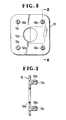
- Figure 8 is a front elevational view of a mounting plate constituting another part of the strap fastener;
- Figure 9 is a cross-sectional view taken along line IX - IX of Figure 8;
- Figures 10 and 11 are cross-sectional views illustrative of the operation of the strap fastener of Figure 1;
- Figure 12 is a front elevational view of a modified strap fastener according to the present invention;
- Figure 13 is a cross-sectional view taken along line XIII - XIII of Figure 12;
- Figure 14 is a rear view of Figure 12;
- Figure 15 is a front elevational view of another modified form of strap fastener;
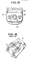
- Figure 16 is a cross-sectional view taken along line XVI - XVI of Figure 15;
- Figure 17 is a rear view of Figure 15; and
- Figure 18 is a perspective view of a knapsack having straps secured in a manner known in the art.
- Referring now to the drawings and Figure 1 in particular, there is shown a
strap fastener 10 which comprises afastener body 11, amounting plate 12 and asocket member 13 all molded of synthetic resin. Thefastener body 11 includes abase plate 14 having a laterally outwardly extendinglug 15 at one or its upper end, a pair ofco-axial pins 16 at the other or its lower end, a laterally outwardly extendinglocking prong 17 intermediate between thelug 15 and thepin 16, and a laterally inwardly extendingplug 18 opposite to theprong 17. Aflange 19 having aslit 20 extends upwardly from thelug 15. Thebase plate 14 is provided adjacent to thelug 15 with a laterallyelongated slot 21 so that the upper end portion of thebase plate 14 posesses a certain degree of resiliency which is large enough to enable thelug 15 to tilt about its distal end upwardly away from theprong 17. - The
fastener body 11 further includes acover plate 22 having a plurality of laterallyelongated openings lower flange portions 27 pivotally connected to therespective pins 16 of thebase plate 14, and anupper flange portion 28 having alocking projection 29 engageable in complementarilyshaped recess 30 formed in the lower surface of thelug 15. Thefirst opening 23 is defined between theflanged portions 27 and afirst cross bar 31; the second opening 24 between thefirst cross bar 31 and asecond cross bar 32; the third opening 25 between thesecond cross bar 32 and athird cross bar 33; and the fourth opening 26 between thethird cross bar 33 and theupper flange portion 28. Thesecond cross bar 32 is slightly off-set from the common upper plane of thecover plate 22 so as to make the strap S lie substantially flush with the upper surface of thecover 22. Thethird cross bar 33 has alongitudinal locking ridge 33a extending along its rear edge and projecting into the third opening 25. With the strap S passed through any of the openings 23 - 26, thecover plate 22 is rotated about thepins 16 in the direction of the arrow into coupling engagement with thebase plate 14 as better shown in Figure 3 when thelocking projection 29 is snapped into therecess 30 to hold thecover 22 and theplate 14 retentively together, while thelocking prong 17 enters into the third opening 25 and holds the strap S immovably against the side wall of thethird cross bar 33. In this instance, thelocking ridge 33a on thethird cross bar 33 bites into the web of the strap S. - The
plug 18, which extends laterally centrally from thebase plate 14 in opposition to thelocking prong 17, has a hollow cylindrical configuration and includes astem portion 18a integral with thebase plate 14 and an enlargedhead portion 18b separated by an interruptedannular shoulder 18c from thestem portion 18a. The hollowcylindrical plug 18 further includes a plurality (four in the illustrated embodiment) oflongitudinal slits 18d in a criss-cross formation, as better shwon in Figure 4, to render theplug 18 resilient and radially inwardly deformable. Thehead portion 18b has atapered end 18e. - The
base plate 14 and thecover plate 22 may be conveniently, though not exclusively, fabricated by injection-molding in assembled condition. - The
mounting plate 12 to be interposed between thefastener body 11 and thesocket member 13 is generally rectangular in shape and has acentral aperture 12a for receiving a portion of thesocket member 13 and a plurality of laterally extendinganchoring posts 12b each with an axialblind hole 12c, there being four of these posts equally spaced around thecentral aperture 12a as better shown in Figure 8. - The
socket member 13, which constitutes another part of thestrap fastener 10, includes a substantiallyrectangular plate 13a and acylindrical neck 34 extending centrally from thebase plate 13a. Thesocket member 13 further has astepped bore 35 extending through thebase plate 13a and theneck 34. Thestepped bore 35 is composed of a small-diameter portion 35a extending concentrically through thecylindrical neck 34, and a large-diameter portion 35b extnding through thebase plate 13a. The large- and small-diameter portions annular step 37 which is lockingly engageable with the interruptedannular shoulder 18c when theplug 18 is snapped in thestepped bore 35. The inside diameter of the small-diameter portion 35a is substantially the same as, preferably slightly larger than, the outside diameter of thecylindrical stem 18a of theplug 18. The outside diameter of thehead 18b of theplug 18 is larger than the inside diameter of the small-diameter portion 35a and is smaller than the inside diameter of the larger-diameter portion 35b. As shown in Figure 6, thesocket 13 is provided with a plurality (four in number in this embodiment) ofcountersunk holes 38 at locations registering with theanchoring posts 12b of themounting plate 12. - With this construction, the
mounting plate 12 and thesocket member 13 are first brought into coupling engagement with each other by inserting theneck 34 of thesocket 13 into thecentral aperture 12a of themounting plate 12 through an opening in a substrate such as sheet of fabric or leather C of a knapsack, with the anchoringposts 12b received in thecorresponding holes 38. Thelugs 12b may be plastically deformed by press or with heat to swell out and anchor within thecountersunk holes 38, thereby joining themounting plate 12 and thesocket member 13 with the fabric sheet C sandwiched therebetween, as better shown in Figure 10. - The
fastener body 11 is then taken into coupling engagement with thesocket member 13, which has been united with themounting plate 12, by inserting theplug 18 into thestepped bore 35. As thehead 18b of theplug 18 advances along the small-diameter portion 35a of thestepped bore 35, thehead 18b is resiliently deformed radially inwardly. A further forward movement of theplug 18 causes thehead 18b to be snapped into the large-diameter portion 35b due to the resiliency of theplug 18. In this instance, the interruptedannular shoulder 18c is held in interlocking engagement with thestep 37 to hold thefastener body 11 and thesocket member 13 in coupled condition, as shown in Figure 11. The back of thefastener body 11 is held in contact with the face of themounting plate 12. - The
fastener body 11 can be rotated at will in either direction about an axis of theplug 18 relative to thesocket member 13 so as to adjust the lateral position of the strap S on the knapsack to suit the particular physical characteristics of the user. In this instance, thefastener body 11 undergoes smaller frictional resistance imposed by themounting plate 12 than by the fabric C of the knapsack. - The strap S can be also adjusted lengthwise by pulling its leading end in and out through the
slot 21 in thebase plate 14 of thefastener body 11, for which purpose and for removal or attachment of the strap S there may be used for example a screwdriver D (placed in theslit 20 in Figure 10 and then tilted in the direction of the arrow A) with which to unlock or release thelocking projection 29 from therecess 30. - Figures 12 through 14 show a modified form of
strap fastener 40 which comprises astrap holder 41 pivotably connected at one end as at 42 to abase plate 43 and at the other end with across bar 44 around which is passed the strap S. Thebase plate 43 carrying aplug 45 identical in construction and function with theplug 18 of Figure 1. Asocket member 46 of thestrap fastener 40 is substantially the same as thesocket member 13 of Figure 1 with the exception that anelongate groove 47 extends arcuately in the face of aneck 48 to a limited angular extent about the axis of astepped bore 49. When theplug 45 is snapped in thestepped bore 49, thegroove 47 loosely receives aprojection 50 on the back of thebase plate 43. With thegroove 47 and theprojection 50 thus provided, thefastener body 41 is rotatable only within the limited angular extent with respect to thesocket member 46 and hence the fabric C of a bag. - Figures 15 through 17 show another modified form of
strap fastener 51 which comprises a fastener body orbuckle 52 composed of amale part 53 and afemale part 54 releasably engageable with each other. Themale part 53 has at one end across bar 55 for mounting the strap S and at the other end ahook 56 releasably engageable with anabutment strip 57 formed on thefemale part 54. Thefemale part 54 includes aplug 58 extending from the back thereof and aprojection 59 disposed adjacent to theplug 58. Theplug 58 is identical in construction and function with theplug 45 of Figure 13. When theplug 58 is snapped with asocket member 60, theprojection 59 is received in anarcuately extending groove 61 in the face of a neck 62 of the of thesocket member 60. The angular movement of thefastener body 52 relative to thesocket member 60 is limited to a certain extent by engagement of theprojection 59 with ends of thearcuate groove 61.
Claims (7)
Applications Claiming Priority (4)
| Application Number | Priority Date | Filing Date | Title |
|---|---|---|---|
| JP143679/86U | 1986-09-19 | ||
| JP14367986 | 1986-09-19 | ||
| JP1986187821U JPH0641450Y2 (en) | 1986-09-19 | 1986-12-05 | Belt fixture |
| JP187821/86U | 1986-12-05 |
Publications (3)
| Publication Number | Publication Date |
|---|---|
| EP0260959A2 true EP0260959A2 (en) | 1988-03-23 |
| EP0260959A3 EP0260959A3 (en) | 1988-09-21 |
| EP0260959B1 EP0260959B1 (en) | 1991-01-23 |
Family
ID=26475347
Family Applications (1)
| Application Number | Title | Priority Date | Filing Date |
|---|---|---|---|
| EP87308204A Expired - Lifetime EP0260959B1 (en) | 1986-09-19 | 1987-09-16 | Strap fastener |
Country Status (10)
| Country | Link |
|---|---|
| US (1) | US4793031A (en) |
| EP (1) | EP0260959B1 (en) |
| JP (1) | JPH0641450Y2 (en) |
| KR (1) | KR900002374Y1 (en) |
| AU (1) | AU574299B2 (en) |
| CA (1) | CA1319495C (en) |
| DE (1) | DE3767625D1 (en) |
| HK (1) | HK61793A (en) |
| MY (1) | MY101354A (en) |
| SG (1) | SG40493G (en) |
Cited By (14)
| Publication number | Priority date | Publication date | Assignee | Title |
|---|---|---|---|---|
| GB2236141A (en) * | 1989-09-14 | 1991-03-27 | Martin Francis Grant | A releasable connector |
| GB2254266A (en) * | 1991-04-01 | 1992-10-07 | Richard Zawitz | Multi-segment annular device |
| GB2256894A (en) * | 1991-06-18 | 1992-12-23 | Titus Int Ltd | Fixing device for securing panels together. |
| FR2679422A1 (en) * | 1991-07-25 | 1993-01-29 | Yoshida Kogyo Kk | Buckle |
| FR2686782A1 (en) * | 1992-01-31 | 1993-08-06 | Velay Moulages | System for closure between a fixed part and a movable part |
| GB2333751A (en) * | 1998-01-26 | 1999-08-04 | Kao Jui Chien | Tool Suspension Rack Assembly |
| FR2814045A1 (en) | 2000-09-20 | 2002-03-22 | Promiles | BACKPACK EQUIPPED WITH AN ANGULAR SHOCK ABSORBER BETWEEN THE BACK OF THE BAG AND THE STRAP AND / OR BELT ASSEMBLY |
| FR2842080A1 (en) * | 2002-07-12 | 2004-01-16 | Exel Ind | "DEVICE FOR QUICK CONNECTION OF A STRAP TO A PORTABLE OBJECT" |
| FR2933279A1 (en) * | 2008-07-07 | 2010-01-08 | Delsey Soc | Luggage carrying device, has luggage anchoring unit including fixation unit fixing strap or reduced-length flexible string that is mounted on support, in rotary manner, where tapered ring is interposed between body and fixation unit |
| WO2010108728A1 (en) | 2009-03-23 | 2010-09-30 | Hirsch Armbaender Gmbh | Band, in particular wristwatch band, having a moveable closure |
| CN105263356A (en) * | 2012-09-05 | 2016-01-20 | 朴帅 | Variable shoulder strap bag, shoulder strap assembly used for the bag, and pivotable device |
| CN106263303A (en) * | 2015-06-23 | 2017-01-04 | 北面服饰公司 | Closure system |
| CN108136235A (en) * | 2015-08-20 | 2018-06-08 | 3M创新有限公司 | Buckle for connection strap band and the respirator beam tool including the buckle |
| US20190150574A1 (en) * | 2014-05-06 | 2019-05-23 | Illinois Tool Works Inc. | Web-connecting assembly having a release button |
Families Citing this family (18)
| Publication number | Priority date | Publication date | Assignee | Title |
|---|---|---|---|---|
| JPH0711608Y2 (en) * | 1989-02-21 | 1995-03-22 | 株式会社アサヒ | Belt attachment |
| JP2525838Y2 (en) * | 1989-04-11 | 1997-02-12 | 株式会社 ニフコ | buckle |
| US5258015A (en) * | 1991-05-03 | 1993-11-02 | American Cyanamid Company | Locking filament caps |
| CA2148974A1 (en) * | 1994-05-13 | 1995-11-14 | Richard P. Brault | Turntable mechanism for a cutting tool |
| US6038747A (en) * | 1999-02-03 | 2000-03-21 | Illinois Tool Works Inc. | Pack waist-belt and buckles therefor |
| US6393672B1 (en) * | 2000-09-19 | 2002-05-28 | Joseph Anscher | D-ring assembly |
| JP2003210424A (en) * | 2002-01-28 | 2003-07-29 | Seiko Instruments Inc | Bio-information observing device |
| US7013497B1 (en) * | 2002-03-15 | 2006-03-21 | Athletic Specialties, Inc. | Strap-securing device |
| TWI227106B (en) * | 2003-11-28 | 2005-01-21 | Inventec Multimedia & Telecom | Housing structure with ring button |
| US20080078792A1 (en) * | 2006-09-29 | 2008-04-03 | Fernando Tages | All Plastic Belt or Strap Clip With Levered Release Arm Operative With Button Mount for Cell Phone or Personal Electronic Device and Method |
| US8567742B2 (en) * | 2011-07-22 | 2013-10-29 | Aquatherm Industries, Inc. | Mounting bracket protection device |
| EP2928339B1 (en) * | 2012-12-05 | 2017-06-14 | Preziosi Point SAGL | Watchstrap, fastening system for a watchstrap and corresponding watch |
| JP6929281B2 (en) * | 2015-11-11 | 2021-09-01 | スリーエム イノベイティブ プロパティズ カンパニー | Jaw strap connector |
| USD794254S1 (en) | 2015-11-11 | 2017-08-08 | 3M Innovative Properties Company | Chinstrap connector for safety helmet |
| TWI589496B (en) * | 2016-09-05 | 2017-07-01 | Guan-Yu Lai | Fixtures |
| US10869518B1 (en) * | 2020-05-05 | 2020-12-22 | Lionhead Helmet Intellectual Properties, Lp | Chin strap assembly for a protective helmet |
| US20220117394A1 (en) * | 2020-10-15 | 2022-04-21 | Arnold Packaging Company | Elastic strap anchor assembly |
| US20260083204A1 (en) * | 2024-09-25 | 2026-03-26 | Gregory A. DUARTE | Clip device for stabilizing items |
Family Cites Families (17)
| Publication number | Priority date | Publication date | Assignee | Title |
|---|---|---|---|---|
| US1237201A (en) * | 1916-09-25 | 1917-08-14 | Charles Green Jr | Fastener. |
| US1503445A (en) * | 1924-01-15 | 1924-07-29 | Providence Stock Company | Bracelet |
| US1696156A (en) * | 1927-11-14 | 1928-12-18 | Scovill Manufacturing Co | Floating-trim stud |
| US1696586A (en) * | 1928-02-29 | 1928-12-25 | Scovill Manufacturing Co | Fastener slide |
| US1904055A (en) * | 1932-04-18 | 1933-04-18 | Scovill Manufacturing Co | Detachable fastener |
| US2486652A (en) * | 1944-07-01 | 1949-11-01 | Scovill Manufacturing Co | Belt buckle with slidable gripper element |
| DE835357C (en) * | 1951-02-06 | 1952-03-31 | Knopf Und Metallwarenfabrik G | Buckle with slider |
| NL266672A (en) * | 1960-07-08 | 1900-01-01 | ||
| US3237257A (en) * | 1964-03-26 | 1966-03-01 | United Carr Inc | Plastic buckle |
| US3406431A (en) * | 1967-05-25 | 1968-10-22 | Coleman Engineering Company In | Releasable fastener for camera cover |
| GB1200245A (en) * | 1968-01-19 | 1970-07-29 | Carr Fastener Co Ltd | Strap buckle |
| US3886632A (en) * | 1974-01-30 | 1975-06-03 | Kidde Co Presto Lock Div | Buckle |
| CA1127581A (en) * | 1978-02-06 | 1982-07-13 | David B. Bartholic | Preparation of fcc charge from residual fractions |
| DE3305884A1 (en) * | 1983-02-19 | 1984-08-23 | Itw-Ateco Gmbh, 2000 Norderstedt | DETACHABLE LOCK |
| CA1247568A (en) * | 1984-01-13 | 1988-12-28 | Greg E. Lowe | Method and structure for attaching adjustable backpack straps |
| DE8425406U1 (en) * | 1984-08-28 | 1985-01-10 | Dewitz, Albrecht von, 7992 Tettnang | DEVICE FOR FASTENING THE STRAPS OF A BACKPACK |
| JPH0130883Y2 (en) * | 1984-12-11 | 1989-09-21 |
-
1986
- 1986-12-05 JP JP1986187821U patent/JPH0641450Y2/en not_active Expired - Lifetime
-
1987
- 1987-09-03 MY MYPI87001535A patent/MY101354A/en unknown
- 1987-09-08 AU AU78149/87A patent/AU574299B2/en not_active Ceased
- 1987-09-16 DE DE8787308204T patent/DE3767625D1/en not_active Expired - Lifetime
- 1987-09-16 EP EP87308204A patent/EP0260959B1/en not_active Expired - Lifetime
- 1987-09-17 KR KR2019870015879U patent/KR900002374Y1/en not_active Expired
- 1987-09-18 CA CA000547239A patent/CA1319495C/en not_active Expired - Fee Related
- 1987-09-21 US US07/098,943 patent/US4793031A/en not_active Expired - Fee Related
-
1993
- 1993-04-08 SG SG404/93A patent/SG40493G/en unknown
- 1993-06-23 HK HK617/93A patent/HK61793A/en unknown
Cited By (29)
| Publication number | Priority date | Publication date | Assignee | Title |
|---|---|---|---|---|
| GB2236141A (en) * | 1989-09-14 | 1991-03-27 | Martin Francis Grant | A releasable connector |
| GB2254266A (en) * | 1991-04-01 | 1992-10-07 | Richard Zawitz | Multi-segment annular device |
| GB2254266B (en) * | 1991-04-01 | 1995-01-11 | Richard Zawitz | Multi-segment annular device |
| GB2256894B (en) * | 1991-06-18 | 1994-11-16 | Titus Int Ltd | Fixing device |
| GB2256894A (en) * | 1991-06-18 | 1992-12-23 | Titus Int Ltd | Fixing device for securing panels together. |
| US5226808A (en) * | 1991-06-18 | 1993-07-13 | Titus International Limited | Fixing device |
| FR2679422A1 (en) * | 1991-07-25 | 1993-01-29 | Yoshida Kogyo Kk | Buckle |
| FR2686782A1 (en) * | 1992-01-31 | 1993-08-06 | Velay Moulages | System for closure between a fixed part and a movable part |
| GB2333751A (en) * | 1998-01-26 | 1999-08-04 | Kao Jui Chien | Tool Suspension Rack Assembly |
| FR2814045A1 (en) | 2000-09-20 | 2002-03-22 | Promiles | BACKPACK EQUIPPED WITH AN ANGULAR SHOCK ABSORBER BETWEEN THE BACK OF THE BAG AND THE STRAP AND / OR BELT ASSEMBLY |
| EP1190642A1 (en) * | 2000-09-20 | 2002-03-27 | Promiles | Backpack with an angular damper between the back of the backpack and the shoulder straps and/or the belt unit |
| US6637631B2 (en) | 2000-09-20 | 2003-10-28 | Decathlon | Knapsack fitted with an angular damper between the back of the bag and the strap and/or belt assembly |
| FR2842080A1 (en) * | 2002-07-12 | 2004-01-16 | Exel Ind | "DEVICE FOR QUICK CONNECTION OF A STRAP TO A PORTABLE OBJECT" |
| FR2933279A1 (en) * | 2008-07-07 | 2010-01-08 | Delsey Soc | Luggage carrying device, has luggage anchoring unit including fixation unit fixing strap or reduced-length flexible string that is mounted on support, in rotary manner, where tapered ring is interposed between body and fixation unit |
| WO2010108728A1 (en) | 2009-03-23 | 2010-09-30 | Hirsch Armbaender Gmbh | Band, in particular wristwatch band, having a moveable closure |
| EP2893834A4 (en) * | 2012-09-05 | 2016-05-25 | Sol Park | Variable shoulder strap bag, shoulder strap assembly used for the bag, and pivotable device |
| CN105263356A (en) * | 2012-09-05 | 2016-01-20 | 朴帅 | Variable shoulder strap bag, shoulder strap assembly used for the bag, and pivotable device |
| CN105263356B (en) * | 2012-09-05 | 2017-07-07 | 株式会社Xix | The deformable bag of shoulder belt, its shoulder strap assembly for using and rotatable connection type equipment |
| US20190150574A1 (en) * | 2014-05-06 | 2019-05-23 | Illinois Tool Works Inc. | Web-connecting assembly having a release button |
| US11071356B2 (en) * | 2014-05-06 | 2021-07-27 | Illinois Tool Works Inc. | Web-connecting assembly having a release button |
| EP3178345A1 (en) * | 2015-06-23 | 2017-06-14 | The North Face Apparel Corp. | Fastener |
| US9750328B2 (en) | 2015-06-23 | 2017-09-05 | The North Face Apparel Corp. | Fastener systems |
| EP3300621A1 (en) * | 2015-06-23 | 2018-04-04 | The North Face Apparel Corp. | Wearable pack with adjustable tensile member and adjusment mechanism |
| EP3181004A3 (en) * | 2015-06-23 | 2017-08-30 | The North Face Apparel Corp. | Adjustable length strap |
| CN106263303B (en) * | 2015-06-23 | 2020-05-29 | 北面服饰公司 | Fastener system |
| CN106263303A (en) * | 2015-06-23 | 2017-01-04 | 北面服饰公司 | Closure system |
| CN108136235A (en) * | 2015-08-20 | 2018-06-08 | 3M创新有限公司 | Buckle for connection strap band and the respirator beam tool including the buckle |
| US10702024B2 (en) | 2015-08-20 | 2020-07-07 | 3M Innovative Properties Company | Buckle for connecting strap and respirator harness including the same |
| CN108136235B (en) * | 2015-08-20 | 2021-10-01 | 3M创新有限公司 | Buckle for connecting straps and respirator harness including the buckle |
Also Published As
| Publication number | Publication date |
|---|---|
| KR900002374Y1 (en) | 1990-03-26 |
| SG40493G (en) | 1993-06-11 |
| US4793031A (en) | 1988-12-27 |
| AU7814987A (en) | 1988-03-31 |
| EP0260959A3 (en) | 1988-09-21 |
| EP0260959B1 (en) | 1991-01-23 |
| DE3767625D1 (en) | 1991-02-28 |
| CA1319495C (en) | 1993-06-29 |
| MY101354A (en) | 1991-09-05 |
| JPS63127409U (en) | 1988-08-19 |
| HK61793A (en) | 1993-07-02 |
| JPH0641450Y2 (en) | 1994-11-02 |
| AU574299B2 (en) | 1988-06-30 |
| KR880011426U (en) | 1988-08-25 |
Similar Documents
| Publication | Publication Date | Title |
|---|---|---|
| EP0260959B1 (en) | Strap fastener | |
| US5150504A (en) | Universal tether apparatus | |
| US4827578A (en) | Harness | |
| EP1018609B1 (en) | Cord fastener | |
| US6510592B1 (en) | Clip for attaching pouches and similar devices | |
| US4924557A (en) | Harness | |
| US5490309A (en) | Fastener assembly | |
| US4932362A (en) | One finger quick release animal collar | |
| US5735024A (en) | Fastening mechanism for connecting articles and the like together | |
| US5143266A (en) | Harness | |
| US5471716A (en) | Buckle | |
| EP1325690B1 (en) | Attachment structure for buckles | |
| US5144695A (en) | Baseball cap retention device | |
| EP3641582B1 (en) | Magnet hook | |
| US6085393A (en) | Badge strap attachment | |
| US20180153266A1 (en) | Removable Belt Buckle System | |
| US5491911A (en) | Fastening means to secure a gaiter to a shoe | |
| US6290112B1 (en) | Belt mounted key holder | |
| US6145172A (en) | Locking device for a side-release buckle | |
| KR20000076673A (en) | Modular attachment system | |
| EP0761115A2 (en) | Belt with micro-adjustment buckle means | |
| CA2068783C (en) | Snap-fit button | |
| US11925242B2 (en) | Buckle with pull ring | |
| US4704772A (en) | Snap-fit clasp fastener for bags | |
| EP0300660B1 (en) | Swivel joint |
Legal Events
| Date | Code | Title | Description |
|---|---|---|---|
| PUAI | Public reference made under article 153(3) epc to a published international application that has entered the european phase |
Free format text: ORIGINAL CODE: 0009012 |
|
| AK | Designated contracting states |
Kind code of ref document: A2 Designated state(s): DE FR GB IT |
|
| PUAL | Search report despatched |
Free format text: ORIGINAL CODE: 0009013 |
|
| 17P | Request for examination filed |
Effective date: 19880627 |
|
| AK | Designated contracting states |
Kind code of ref document: A3 Designated state(s): DE FR GB IT |
|
| 17Q | First examination report despatched |
Effective date: 19900618 |
|
| GRAA | (expected) grant |
Free format text: ORIGINAL CODE: 0009210 |
|
| AK | Designated contracting states |
Kind code of ref document: B1 Designated state(s): DE FR GB IT |
|
| ITF | It: translation for a ep patent filed | ||
| REF | Corresponds to: |
Ref document number: 3767625 Country of ref document: DE Date of ref document: 19910228 |
|
| ET | Fr: translation filed | ||
| PLBE | No opposition filed within time limit |
Free format text: ORIGINAL CODE: 0009261 |
|
| STAA | Information on the status of an ep patent application or granted ep patent |
Free format text: STATUS: NO OPPOSITION FILED WITHIN TIME LIMIT |
|
| 26N | No opposition filed | ||
| ITPR | It: changes in ownership of a european patent |
Owner name: CAMBIO RAGIONE SOCIALE;YKK CORPORATION |
|
| REG | Reference to a national code |
Ref country code: FR Ref legal event code: CD |
|
| PGFP | Annual fee paid to national office [announced via postgrant information from national office to epo] |
Ref country code: FR Payment date: 19950619 Year of fee payment: 9 |
|
| PGFP | Annual fee paid to national office [announced via postgrant information from national office to epo] |
Ref country code: GB Payment date: 19950907 Year of fee payment: 9 |
|
| PGFP | Annual fee paid to national office [announced via postgrant information from national office to epo] |
Ref country code: DE Payment date: 19951031 Year of fee payment: 9 |
|
| PG25 | Lapsed in a contracting state [announced via postgrant information from national office to epo] |
Ref country code: GB Effective date: 19960916 |
|
| PG25 | Lapsed in a contracting state [announced via postgrant information from national office to epo] |
Ref country code: FR Effective date: 19960930 |
|
| GBPC | Gb: european patent ceased through non-payment of renewal fee |
Effective date: 19960916 |
|
| PG25 | Lapsed in a contracting state [announced via postgrant information from national office to epo] |
Ref country code: DE Effective date: 19970603 |
|
| REG | Reference to a national code |
Ref country code: FR Ref legal event code: ST |
|
| REG | Reference to a national code |
Ref country code: FR Ref legal event code: ST |
|
| PG25 | Lapsed in a contracting state [announced via postgrant information from national office to epo] |
Ref country code: IT Free format text: LAPSE BECAUSE OF NON-PAYMENT OF DUE FEES;WARNING: LAPSES OF ITALIAN PATENTS WITH EFFECTIVE DATE BEFORE 2007 MAY HAVE OCCURRED AT ANY TIME BEFORE 2007. THE CORRECT EFFECTIVE DATE MAY BE DIFFERENT FROM THE ONE RECORDED. Effective date: 20050916 |