EP0261344B1 - Plateforme de support extensible et très basse - Google Patents
Plateforme de support extensible et très basse Download PDFInfo
- Publication number
- EP0261344B1 EP0261344B1 EP87110822A EP87110822A EP0261344B1 EP 0261344 B1 EP0261344 B1 EP 0261344B1 EP 87110822 A EP87110822 A EP 87110822A EP 87110822 A EP87110822 A EP 87110822A EP 0261344 B1 EP0261344 B1 EP 0261344B1
- Authority
- EP
- European Patent Office
- Prior art keywords
- pair
- linkages
- end portion
- base
- platform
- Prior art date
- Legal status (The legal status is an assumption and is not a legal conclusion. Google has not performed a legal analysis and makes no representation as to the accuracy of the status listed.)
- Expired - Lifetime
Links
- 238000013459 approach Methods 0.000 claims description 2
- 230000008878 coupling Effects 0.000 claims 1
- 238000010168 coupling process Methods 0.000 claims 1
- 238000005859 coupling reaction Methods 0.000 claims 1
- 239000012530 fluid Substances 0.000 description 5
- 241000219098 Parthenocissus Species 0.000 description 2
- 230000000712 assembly Effects 0.000 description 2
- 238000000429 assembly Methods 0.000 description 2
- 125000006850 spacer group Chemical group 0.000 description 2
- 241000935985 Certhiidae Species 0.000 description 1
- 238000005452 bending Methods 0.000 description 1
- 238000010276 construction Methods 0.000 description 1
- 230000007423 decrease Effects 0.000 description 1
- 230000007812 deficiency Effects 0.000 description 1
- 230000000694 effects Effects 0.000 description 1
- 239000000463 material Substances 0.000 description 1
- 230000003340 mental effect Effects 0.000 description 1
- 210000003205 muscle Anatomy 0.000 description 1
- 238000009877 rendering Methods 0.000 description 1
- 238000005303 weighing Methods 0.000 description 1
Images


Classifications
-
- B—PERFORMING OPERATIONS; TRANSPORTING
- B66—HOISTING; LIFTING; HAULING
- B66F—HOISTING, LIFTING, HAULING OR PUSHING, NOT OTHERWISE PROVIDED FOR, e.g. DEVICES WHICH APPLY A LIFTING OR PUSHING FORCE DIRECTLY TO THE SURFACE OF A LOAD
- B66F7/00—Lifting frames, e.g. for lifting vehicles; Platform lifts
- B66F7/06—Lifting frames, e.g. for lifting vehicles; Platform lifts with platforms supported by levers for vertical movement
- B66F7/08—Lifting frames, e.g. for lifting vehicles; Platform lifts with platforms supported by levers for vertical movement hydraulically or pneumatically operated
-
- B—PERFORMING OPERATIONS; TRANSPORTING
- B64—AIRCRAFT; AVIATION; COSMONAUTICS
- B64F—GROUND OR AIRCRAFT-CARRIER-DECK INSTALLATIONS SPECIALLY ADAPTED FOR USE IN CONNECTION WITH AIRCRAFT; DESIGNING, MANUFACTURING, ASSEMBLING, CLEANING, MAINTAINING OR REPAIRING AIRCRAFT, NOT OTHERWISE PROVIDED FOR; HANDLING, TRANSPORTING, TESTING OR INSPECTING AIRCRAFT COMPONENTS, NOT OTHERWISE PROVIDED FOR
- B64F5/00—Designing, manufacturing, assembling, cleaning, maintaining or repairing aircraft, not otherwise provided for; Handling, transporting, testing or inspecting aircraft components, not otherwise provided for
- B64F5/10—Manufacturing or assembling aircraft, e.g. jigs therefor
-
- B—PERFORMING OPERATIONS; TRANSPORTING
- B66—HOISTING; LIFTING; HAULING
- B66F—HOISTING, LIFTING, HAULING OR PUSHING, NOT OTHERWISE PROVIDED FOR, e.g. DEVICES WHICH APPLY A LIFTING OR PUSHING FORCE DIRECTLY TO THE SURFACE OF A LOAD
- B66F7/00—Lifting frames, e.g. for lifting vehicles; Platform lifts
- B66F7/06—Lifting frames, e.g. for lifting vehicles; Platform lifts with platforms supported by levers for vertical movement
- B66F7/0625—Lifting frames, e.g. for lifting vehicles; Platform lifts with platforms supported by levers for vertical movement with wheels for moving around the floor
-
- B—PERFORMING OPERATIONS; TRANSPORTING
- B66—HOISTING; LIFTING; HAULING
- B66F—HOISTING, LIFTING, HAULING OR PUSHING, NOT OTHERWISE PROVIDED FOR, e.g. DEVICES WHICH APPLY A LIFTING OR PUSHING FORCE DIRECTLY TO THE SURFACE OF A LOAD
- B66F7/00—Lifting frames, e.g. for lifting vehicles; Platform lifts
- B66F7/06—Lifting frames, e.g. for lifting vehicles; Platform lifts with platforms supported by levers for vertical movement
- B66F7/0691—Asymmetric linkages, i.e. Y-configuration
Definitions
- This invention relates to a low profile lift assembly having a horizontal support platform that is movable toward and away from a base in parallel relationship thereto.
- the assembly has unique extension structure which significantly decreases the ratio of collapsed height to extended height, maximizes the permissible load on the operating components and reduces the amount of force necessary to overcome resistance to movement when the assembly is extended from its initially fully collapsed state.
- the portable work stand thereby presented is especially useful for supporting a mechanic in a horizontal position or for carrying a load such as the engine of an aircraft or an automobile, and includes a number of linkages which provide substantially equal support over the entire area of the work platform regardless of the degree of extension of the latter from the base.
- Aircraft mechanics and similar workers have long felt a need for a roller creeper having a platform which can be extended upwardly to enable the user to more conveniently work on the underside of an aircraft which is normally substantially higher from the ground than the underside of an automobile or truck.
- Conventional practice of mechanics has been to raise the effective height of typical creepers in incremental units by adding books, boxes, boards or other make-shift members to the top of the creeper until a proper elevation is approximately attained.
- Such practice is inconvenient at best and usually cannot provide support for the worker at just the right height in steady fashion and free of risk.
- comfort of the mechanic is an often overlooked factor which can greatly contribute to work productivity in terms of both the time necessary to complete the job as well as the overall quality of the work once finished.
- a mechanic working on the underside of aircraft without proper support at a comfortable working distance from the aircraft components constantly shifts his or her body to relieve muscle stress and fatigue, and these body movements, whether consciously or unconsciously initiated, substantially increase the time necessary to complete the job and also contribute somewhat to mental stress since the normal train of thought is consequently interrupted.
- a wheeled dolly available which is provided with a vertically extensible support platform for carrying tools, engines or other items and that is selectively movable both in vertical as well as in horizontal directions.
- a dolly for removing engines from vehicles should be lightweight and thus readily portable, while having sufficient strength to safely carry the engine at a height convenient for performing work functions thereon, rendering unnecessary the practice of transferring the engine from the dolly to a work table once the engine is removed from the vehicle.
- a portable wheeled dolly which can be rolled up a ramp into the fuselage, and wherein a work supporting surface can be raised a sufficient height in order to met the engine as it is uncoupled from its normal elevated position with respect to the helicopter deck.
- Scissors lifts often comprise two pairs of elongated, rigid links, one pair of which is pivotally connected to the base and shiftably connected to the platform, and the other pair of which is pivotally connected to the platform and shiftably connected to the base.
- a hydraulic piston and cylinder assembly secured to the base and coupled to the linkages is operable such that extension or retraction of the piston shifts the platform either away from or toward the base.
- adjacent ends of the linkages simultaneously shift toward one another. The result is that the raised platform is no longer supported equally in all corners by the linkages; one end of the platform in effect "overhangs" the linkages.
- scissors lift tables are often manufactured of relatively heavy materials and are derated in capacity so that loads carried by the unsupported, or cantilevered region of the platform cannot tip over the assembly. As can be appreciated, such scissors lift tables are consequently heavy and cannot be readily transported by a single person.
- the present invention represents a significant advance in the art by provision of a support platform assembly having two pairs of opposite linkage sets which provide substantially equal support to all areas of the platform regardless of the elevation of the latter. Furthermore, relatively lightweight components may be used so that the assembly can easily be manually transported when necessary. The ratio of the extended height to the collapsed height of the support platform is significantly increased and is approximately twice that of the known comparable art when load bearing to weight and complexity factors are taken into account.
- the assembly of the present invention is of sufficient strength for supporting an engine, a worker, or a number of tools as may be necessary.
- the linkage sets include four spaced, generally parallel linkages which extend between the platform and the base, as well as four relatively short links which are pivotally connected to the linkages at bisecting locations thereon.
- the links are also pivotally connected to either the base or the support platform.
- a hydraulic piston and cylinder assembly is coupled by swivel members to torque arms fixedly connected to the short links, and the torque arms are strategically positioned to improve the mechanical advantage of the linkages and links.
- the torque arms considerably reduce the amount of force which the hydraulic piston and cylinder assembly must exert to force the links apart when the platform is initially raised from a fully collapsed position.
- the lifting force has been reduced from approximately 7,300 pounds to approximately 2,600 pounds.
- the addition of the swivel members which interconnect the piston and cylinder assembly and the torque arms also enables the use of a longer piston and cylinder assembly than would otherwise be possible because of the limited distance between the support points for the assembly when the linkages are fully collapsed.
- the cylinder and piston are each provided with trunnions which pivotally carry the swivel members, and both of the trunnions are engageable with stops connected to the platform and base respectively which provide support for the trunnions as the piston is extended and resist the tendency of the piston and cylinder assembly to rotate and "right itself", and thereby assist the torque arms in causing swinging movement of the links and linkages.
- the addition of the stops in the above example has been found to further reduce the force necessary to shift the linkages apart, from the aforesaid value of 2,600 pounds when the torque arms alone are utilized to a value of 1,200 pounds when the stops are added.
- a spring yieldably biases the swivel members away from positions wherein the longitudinal axes of the latter are parallel with the axis of the piston. Misalignment of the swivel members relative to the line of force presented by the piston improves the mechanical advantage of the links, linkages and swivel member during retraction of the piston as the assembly is collapsed.
- a lug fixedly coupled to each of the swivel members is engageable with corresponding torque arms to limit the inclination of the longitudinal axis of the hydraulic cylinder and piston assembly relative to both of the swivel members.
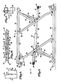
- An extensible support platform assembly broadly designated 20, is illustrated in Figs. 1-10 and includes a base 22 and a platform means or platform 24, the latter of which includes a removable flat top 26.
- the base 22 (Figs. 1-5) is generally rectangular and tubular, and has two side bars 28, two end bars 30 connected to the side bars 28, two intermediate bars 32 (Figs. 2-4) which join the side bars 28, and a first stop means or stop 34 which is mounted atop on of the intermediate bars 32.
- the base 22 also carries four wheels 36 located to retain base 22 above the level of the ground.
- the platform means 24, similar to the base 22 is tubular and generally rectangular, and includes two spaced side bars 40 (see e.g., Fig. 2), two end bars 42 joined to the side bars 40, two intermediate bars 44 interconnecting the side bars 40 and a second stop means or stop 46 which is mounted to the underside of one of the intermediate bars 44.
- the platform 24, including the bars 40, 42 and 44 extends in a normally horizontal plane thereby defining a work supporting surface which is parallel to a plane that passes through the longitudinal axes of bars 28, 30 and 32 of base 22.
- Two spaced linkages 48 comprising a first pair of linkages, each have a lower segment connected to the base 22 by pivots 50 for swinging movement about a common horizontal axis as illustrated in Figs. 1 and 3-5.
- Each of the first pair of linkages 48 is also shiftably coupled to the platform 24 by means of two rollers 52 which are received in C shaped channels 53 forming as part one of the side bars 40.
- the rollers 52 are coupled to elements 55 fixed to upper segments of respective linkages 48, and a horizontal rod 57 securely interconnects the two elements 55.
- two spaced linkages 56 comprising a second pair of linkages, are each connected at an upper portion thereof to one of the side bars 40 of platform 24 by means of pivots 58.
- the linkages 56 are also shiftably connected to the base 22 by rollers 60 which resemble rollers 52 and which are received in a C-shaped channel 61 forming a portion of side bars 28 of base 22.
- Rollers 60 are coupled to elements 63 fixed to a lower portion of a respective linkage 56, and the linkages 56 swing in an arc as rollers 60 shift along channel 61.
- a rod 65 fixedly interconnects the two elements 63.
- Each of a first pair of link means comprising relatively short links 64, is coupled at a lower end portion thereof by a respective pivot 66 to an intermediate region of one of the first pair of linkages 48.
- An upper end of each of the links 64 is connected by a pivot 68 to one of the side bars 40 of the platform 24, and all of the pivots 66, 68 are oriented for swinging movement of the links 64 about horizontal axes.
- pivot 66 is located at a midpoint along the length of the respective linkage 48 to bisect the latter and to form an isoceles triangle, although it is at least theoretically possible to locate the pivots 66 at another position along the length of linkages 48 somewhat spaced from the midpoint thereof.
- Two links 70 comprising a second pair of link means, each have an upper portion that is coupled by pivots 72 to a midpoint of one of the linkages 56.
- a lower portion of each link 70 is connected by a pivot 74 to one of the side bars 28 of base 22.
- Pivots 72, 74 are oriented for swinging movement of the respective link 70 about horizontal axes, and the links 70, along with a lower region of the linkages 56 and a portion of the side bars 28 of base 22, also form an isoceles triangle.
- the linkages 48 swing in an arc about pivots 50 and rollers 52 while linkages 56 swing in an arc about pivots 58 and rollers 60 to thereby move the platform 24 either toward or away from the base 22 while maintaining the platform 24 in parallel relationship with the base 22.
- the first pair of links 64 swing in vertical planes about pivots 66, 68 while the second pair of links 70 swing in vertical planes about pivots 72, 74.
- Extensible means 76 comprising a hydraulically powered piston and cylinder assembly has a cylinder 78 and a reciprocable piston 80 (Figs. 5 and 6).
- a trunnion 82 is secured to an end of the piston 80 and comprises a first end portion of the extensible means 76.
- a trunnion 84 similar to trunnion 82 is fixed to the end of the cylinder 78 remote from piston 80 and comprises a second end portion of the extensible means 76.
- a first elongated swivel member 86 and a third elongated swivel member 88 are both pivotally coupled to trunnion 82 for swinging movement about a common horizontal axis.
- Coil springs 90 are secured to trunnion 82 and engage pins 92 affixed to members 86, 88 for biasing the latter in a clockwise direction about trunnion 82 when viewed in the direction shown in Fig. 5.
- a second elongated swivel member 94 and a fourth elongated swivel member 96 are pivotally coupled to the trunnion 84 of the second end portion of the extensible means 76 for swinging movement about a common horizontal axis.
- a first torque arm means including an arm 102, interconnects the first swivel member 86 and one of the first pair of links 64.
- the first torque arm means also includes a third torque arm 104 (Fig. 2) that interconnects the third swivel member 88 and the remaining one of the first pair of links 64.
- the torque arms 102, 104 are connected by pivots 105 to swivel members 86, 88 respectively for swinging movement about a common horizontal axis.
- An upper portion of each of the torque arms 102, 104 is fixedly secured to a horizontally extending, somewhat bowed cross bar 108 (Fig. 2) which in turn is fixed at opposite ends to a lower region of a respective one of the two links 64.
- a second torque arm means pivotally interconnects the second swivel member 94 and the the second pair of links 70. More particularly, a second torque arm 110 and a fourth torque arm 112 are each coupled by pivots 114 to swivel members 94, 96 for swinging movement about a common horizontal axis, and a lower end of the torque arms 110, 112 is fixedly secured to a cross bar 116 (Fig. 2) which extends horizontally and which is fixed at each end to an upper region of both of the links 70.
- two elongated braces 118, 120 extend diagonally within assembly 20 and include a lower portion rigidly connected to a lower region of torque arms 102, 104 respectively adjacent pivots 105 and also include an upper portion that is fixed to an upper region of each of the first pair of links 64.
- braces 122, 124 extend diagonally within assembly 20 and include an upper portion fixedly coupled to an upper region of torque arms 110, 112 correspondingly adjacent pivots 114 and also include a lower portion mounted to a lower region of each of the second pair of links 70.
- a source of hydraulic pressure for powering the extensible means 76 may take the form of a hydraulic pump 126, as shown in Figs. 1-2 and 4-5.
- the pump 126 has a telescopically extensible handle 128 which is swingable about a horizontal axis. Swinging reciprocation of handle 128 causes pump 126 to develop fluid pressure that is then directed through one of two hoses (not shown) in accordance with a selected position of a switching valve 130.
- the hoses from the pump 126 are connected to opposite end segments of cylinder 78, so that piston 80 can be extended or retracted depending on the selected position of valve 130.
- Fig. 8 depicts in more detail one of the pivots 72 which interconnects an upper portion of one of the second pair of links 70 with an intermediate region of one of the second pair of linkages 56.
- the pivot 72 comprises an enlarged, tool-engaging head 132 and a threaded, reduced diameter portion 134 remote from head 132.
- a spacer 136 is secured to linkage 56 to maintain link 70 in nonbinding, spaced relationship to linkage 56.
- Pivot 66, interconnecting one of the links 64 and one of the linkages 48, is similar to pivot 72 as illustrated in Fig. 8 and this is not shown in detail.
- Fig. 9 illustrates the particular nature of one of the rollers 52 which rolls along one of the channels 53 as the assembly 20 is extended or collapsed.
- Roller 52 extends horizontally from the element 55 in opposite relation to outwardly extending rod 57, and element 55 is fixed to an upper portion of a respective one of the first pair of linkages 48 by means of an intermediate spacer 138.
- Rollers 60, elements 63 and the associated components are similar to rollers 52 and elements 55 and consequently are not also illustrated in detail.
- Extension of piston 80 causes all of the swivel members 86, 88, 94 and 96 to simultaneously exert a force on the corresponding torque arm 102, 104, 110 and 112, and in turn a force is exerted by the torque arms on the first pair of links 64 and the second pair of links 70 to cause all of the latter to swing in an arc about the first pair of linkages 48 and the second pair of linkages 56.
- the torque arms 102, 104, 110, 112 exert a rotary force on corresponding links 64, 70 as well as pressure in a generally horizontal direction.
- the torque produced by arms 102, 104, 110 and 112 reduces the force required to be generated by the cylinder 78 to about 40% of the value that would be required without such torque.
- a hydraulic piston and cylinder assembly hypothetically directly coupled between pivots 66 and 72 would have a very low mechanical advantage and exert severe pressure on the remaining components and interconnections thereof of the assembly, especially when the assembly is in a fully collapsed position and a significant "startup" force needs to be generated.
- swivel members 86, 88, 94 and 96 which function to transmit force from the extensible means 76 to respective torque arms 102, 104, 110 and 112, also permit the use of a longer cylinder 78 and piston 80 then would otherwise be possible.
- the dashed line identified as 140 in the schematic depiction of assembly 20 in Fig. 10 extends through pivots 106, 114 which are forced away from each other when platform 24 is raised, and it is noteworthy that this dashed line is not parallel with the axis of movement of extensible means 76.
- trunnions 82 and 84 engage stops 34, 46 which prevent the trunnions 82, 84 from further rotating in a clockwise direction, viewing Figs. 2-4.
- stops 34, 46 prevent the trunnions 82, 84 from further rotating in a clockwise direction, viewing Figs. 2-4.
- Swivel members 86, 88, 94 and 96 are instead caused to rotate about trunnions 82, 84 thereby further reducing the overall force which must be generated by the extensible means 76 to about 20% of the force that would be required in an otherwise comparable assembly without such torque arms, swivel members and trunnions in contact with the stops respectively fixed to the base and work platform.
- valve 130 is manually switched to allow hydraulic fluid pressure to flow toward the end of cylinder 78 remove from trunnion 84 whereby piston 80 withdraws intp cylinder 78.
- Retraction of piston 80 biases extensible means 76 in a clockwise direction, whereupon torque arms 102, 104, 110, 112 engage lugs 143 integrally formed in swivel members 86, 88, 94 and 96 correspondingly (see, e.g., lug 142 on swivel member 96 in Fig.
- Fig. 7 depicts in detail the lug 142 formed on fourth swivel member 96 and which is engageable with fourth torque arm 112, although similar lugs are disposed on swivel members 86, 88 and 94.
- springs 90 exert a rotary, clockwise force viewing Fig. 5 on swivel members 86, 88 while springs 98 exert a clockwise bias on swivel members 94, 96.
- the swivel members 86, 88, 94, 96 swing in arcs until the integrally formed lug thereon (i.e., such as lug 142) contacts respective torque arms 102, 104, 110 and 112.
- swivel members 86, 88, 94, 96 have reached a point of "cam over" with respect to the line of force generated by extensible means 76, and the lugs 142 thereafter stiffen respective swivel members 86, 88, 94, 96 to cause the latter to push instead of rotate.
- the lower bent portion of each of the first pair of linkages 48 in cooperation with the upper bent portion of each of the second pair of linkages 56 allows the assembly 20 to be more fully nested when collapsed than would otherwise be possible, since the bent portions clear sleeves 52 and 60 as well as the remaining, major regions of the linkages 48, 56.
- the lateral box in crossbars 108, 116 provides clearance for extensible means 76 when the assembly 20 is fully collapsed and also assists in preventing side bars 28, 40 from deflecting inward when the platform 24 is raised.
- the use of the torque arms 102, 104, 110 and 112, in combination with trunnions 82, 84 in contact with stops 34, 46 enables the assembly 20 to be extended from a fully collapsed state with a minimum of generated hydraulic pressure which in turn enables the use of relatively lighter weight tubing and interconnecting components than would otherwise be possible.
- the assembly 20 can be readily carried by the worker and yet have sufficient strength for supporting an engine or other relatively heavy loads.
- the assembly 20 when constructed in accordance with the principles of the present invention can conservatively support a load of over 600 pounds, while weighing only approximately 92 pounds.
- the platform 24 can be extended to a height for supporting a mechanic, an engine or other items at a convenient working position while the platform 24 is securely supported in all four corner regions by linkages, in contrast to prior art "scissors type" lift tables which become more unsteady as the table is extended. Furthermore, orientation of the torque arms, swivel members and various linkages is such that the platform 24 can be lowered to such an extent that the assembly 20 assumes an extremely low profile when collapsed, allowing the same to be received in space having low clearance such as underneath the frame of vehicles.
Landscapes
- Engineering & Computer Science (AREA)
- Life Sciences & Earth Sciences (AREA)
- Geology (AREA)
- Mechanical Engineering (AREA)
- Structural Engineering (AREA)
- Manufacturing & Machinery (AREA)
- Transportation (AREA)
- Aviation & Aerospace Engineering (AREA)
- Forklifts And Lifting Vehicles (AREA)
- Joining Of Building Structures In Genera (AREA)
Claims (9)
- Ensemble de plate-forme de support extensible à profil bas comprenant:
- une base s'étendant de manière générale dans un plan de référence;- un moyen de plate-forme s'étendant de manière générale dans un plan essentiellement parallèle au dit plan de référence et définissant une surface de support de travail;- une première paire de liaisons espacées, chacune étant reliée à pivotement à la dite base et accouplée à déplacement au dit moyen de plate-forme;- une seconde paire de liaisons espacées, chacune étant reliée à pivotement au dit moyen de plate-forme et accouplée à déplacement à la dite base;- chacune des dites premières paires de liaisons et chacune des dites secondes paires de liaisons étant allongées et présentant une région intermédiaire;- une première paire de moyens de liaison, chacun accouplé à pivotement à la dite région intermédiaire de l'une des dites premières paires de liaisons et chacun relié au dit moyen de plate-forme;- une seconde paire de moyens de liaison, chacun accouplé à pivotement à la dite région intermédiaire de l'une des dites secondes paires de liaisons et chacun relié à pivotement à la dite base;- la dite première paire de liaisons pouvant, au cours du mouvement de déplacement le long du dit moyen de plate-forme, et la dite seconde paire de liaisons pouvant, au cours du mouvement de déplacement le long de la dite base, tourner le long d'un arc respectivement autour du dit moyen de plate-forme et autour de la dite base, en vue de d'approcher ou d'éloigner le dit moyen de plate-forme de la dite base tout en maintenant le dit moyen de plate-forme dans une relation essentiellement coplanaire avec la dite base lorsque la dite première paire de moyens de liaison tourne le long d'un arc autour de la dite première paire de moyens de liaison, et lorsque la dite seconde paire de moyens de liaison tourne le long d'un arc autour de la dite seconde paire de liaisons et de la dite base;- un moyen extensible possédant une première portion d'extrémité et une seconde portion d'extrémité et approchable ou éloignable, de manière sélective le long d'un axe, de la dite première portion d'extrémité;- un membre pivotant allongé accouplé à pivotement à l'une des dites portions d'extrémité du dit moyen extensible, en vue d'un déplacement pivotant autour de ce dernier;- un moyen d'arbre de torsion reliant à pivotement le dit membre pivotant et une paire adjacente de l'une des dites première et seconde paires de moyens de liaison;- le dit moyen d'arbre de torsion étant positionné en vue d'exercer une torsion sur une paire adjacente du dit moyen de liaison lorsque la dite seconde portion d'extrémité du dit moyen extensible est éloignée de la dite première portion d'extrémité du dit moyen extensible en vue d'exercer une traction sur le dit membre pivotant et par là sur le dit moyen de bras de torsion, et en vue de provoquer le pivotement du dit premier moyen de liaison et du dit second moyen de liaison le long d'un arc tournant respectivement autour de la dite première paire de liaisons et de la dite seconde paire de liaisons; et- un moyen d'arrêt relié soit au dit moyen de plate-forme soit à la dite base, et pouvant s'accrocher avec respectivement l'une des dites secondes et l'une des dites premières portions d'extrémité du dit moyen extensible, en vue de soutenir le dit moyen extensible pendant son accrochage avec eux, et en vue de s'opposer à la rotation du dit moyen extensible autour d'un axe transversal à son axe de déplacement extensible lorsque la dite seconde portion d'extrémité du dit moyen extensible est éloignée de la dite première portion d'extrémité, en vue d'augmenter ainsi simultanément la traction sur le dit membre pivotant et d'aider le dit moyen de bras de torsion à exercer une torsion sur la dite paire adjacente de moyens de liaison, et en vue de provoquer simultanément le pivotement correspondant de la dite première paire de liaisons et de la dite seconde paire de liaisons autour de la dite base et du dit moyen de plate-forme, de manière à éloigner comme souhaité le dit moyen de plate-forme de la dite base. - Ensemble de plate-forme de support extensible à profil bas selon la revendication 1, caractérisé en ce que l'une des dites premières portions d'extrémité et la dite seconde portion d'extrémité du dit moyen extensible comprennent un tourillon accouplant à pivotement le dit membre pivotant au dit moyen extensible, et pouvant s'accrocher au dit moyen d'arrêt.
- Ensemble de plate-forme de support extensible à profil bas selon la revendication 1, caractérisé en ce qu'une butée est reliée à l'un des dits moyens de bras de torsion et au dit membre pivotant en vue de limiter l'inclinaison du dit membre pivotant par rapport au dit moyen extensible.
- Ensemble de plate-forme de support extensible à profil bas selon la revendication 1, caractérisé en ce qu'il comprend un moyen en vue d'écarter de manière peu résistante le dit membre pivotant depuis une position dans laquelle l'axe longitudinal du dit membre pivotant est parallèle au dit axe de déplacement de la dite seconde portion d'extrémité du dit moyen extensible éloignée de la dite première portion d'extrémité.
- Ensemble de plate-forme de support extensible à profil bas selon la revendication 1, caractérisé en ce que la dite première paire de liaisons et la dite seconde paire de liaisons comprennent chacune des premiers segments mutuellement parallèles, et des seconds segments mutuellement parallèles formant un angle avec les premiers segments respectifs, en vue d'augmenter l'espace libre entre la dite première paire de liaisons et la dite seconde paire de liaisons lorsque le dit moyen de plate-forme s'approche de la dite base.
- Ensemble de plate-forme de support extensible à profil bas comprenant:
- une base s'étendant de manière générale dans un plan de référence;- un moyen de plate-forme s'étendant de manière générale dans un plan essentiellement parallèle au dit plan de référence et définissant une surface de support de travail;- une première paire de liaisons espacées, chacune étant reliée à pivotement à la dite base et accouplée à déplacement au dit moyen de plate-forme;- une seconde paire de liaisons espacées, chacune étant reliée à pivotement au dit moyen de plate-forme et accouplée à déplacement à la dite base;- chacune des dites premières paires de liaisons et chacune des dites secondes paires de liaisons étant allongée et présentant une région intermédiaire;- une première paire de moyens de liaison, chacun accouplé à pivotement à la dite première région intermédiaire de l'une des dites premières paires de liaisons et chacun relié au dit moyen de plate-forme;- une seconde paire de moyens de liaison, chacun accouplé à pivotement à la dite région intermédiaire de l'une des dites secondes paires de liaisons et chacun relié à pivotement à la dite base;- la dite première paire de liaisons pouvant, au cours du mouvement de déplacement le long du dit moyen de plate-forme, et la dite seconde paire de liaison pouvant, au cours du mouvement de déplacement le long de la dite base, tourner le long d'un arc respectivement autour de la dite base et autour du dit moyen de plate-forme, en vue d'approcher ou d'éloigner le dit moyen de plate-forme de la dite base tout en maintenant le dit moyen de plate-forme dans une relation essentiellement coplanaire à la dite base lorsque la dite première paire de moyens de liaison tourne le long d'un arc autour des dits moyens de liaison, et lorsque la dite seconde paire de moyens de liaison tourne le long d'un arc autour de la dite seconde paire de liaisons et de la dite base;- un moyen extensible possédant une première portion d'extrémité et une seconde portion d'extrémité approchable et éloignable, de manière sélective le long d'un axe, de la dite première portion d'extrémité;- un premier membre allongé accouplé à pivotement à la dite première portion d'extrémité du dit moyen extensible, en vue d'un déplacement pivotant autour de ce dernier;- un second membre allongé accouplé à pivotement à la dite seconde portion d'extrémité du dit moyen extensible, en vue d'un déplacement pivotant autour de ce dernier;- un premier moyen d'arbre de torsion reliant à pivotement le dit premier membre et la dite première paire de moyens de liaison;- un second moyen d'arbre de torsion reliant à pivotement le dit second membre et la dite seconde paire de moyens de liaison;- le dit premier moyen d'arbre de torsion et le dit second moyen d'arbre de torsion étant positionnés en vue d'exercer une torsion respectivement sur le premier moyen de liaison et sur le second moyen de liaison lorsque la dite seconde portion d'extrémité du dit moyen extensible est éloignée de la dite première portion d'extrémité du dit moyen extensible en vue de provoquer le pivotement du dit premier moyen de liaison et du dit second moyen de liaison le long d'un arc tournant respectivement autour de la dite première paire de liaisons et autour de la dite seconde paire de liaisons, et en vue de provoquer simultanément le pivotement correspondant de la dite première paire de liaisons et de la dite seconde paire de liaisons autour de la dite base et du dit moyen de plate-forme, de manière à éloigner comme souhaité le dit moyen de plate-forme de la dite base. - Ensemble de plate-forme de support extensible à profil bas selon la revendication 6, caractérisé en ce qu'il comprend un premier moyen d'arrêt relié à la dite base et accrochable avec la dite première portion d'extrémité du dit moyen extensible pendant au moins une partie du temps pendant lequel la dite seconde portion d'extrémité du dit moyen extensible est approchée ou éloignée de la dite première portion d'extrémité; et un second moyen d'arrêt relié au dit moyen de plate-forme et accrochable avec la dite seconde portion d'extrémité du dit moyen extensible au cours d'au moins une partie du temps pendant lequel la dite seconde portion d'extrémité du dit moyen extensible est approchée ou éloignée de la dite première portion d'extrémité, le dit premier moyen d'arrêt et le dit second moyen d'arrêt pouvant pendant l'accrochage avec respectivement la dite première portion d'extrémité et la dite seconde portion d'extrémité être actionnés en vue de faciliter le mouvement correspondant de balancement du dit premier membre et du dit second membre autour du dit moyen extensible lorsque la dite première portion d'extrémité est éloignée de la dite seconde portion d'extrémité en vue de faciliter de ce fait le déplacement le long d'un arc de la dite première paire de moyens de liaison et de la dite seconde paire de moyens de liaison en vue d'éloigner le dit moyen de plate-forme de la dite base.
- Ensemble de plate-forme de support extensible à profil bas comprenant:
- une base s'étendant de manière générale dans un plan de référence;- un moyen de plate-forme s'étendant de manière générale dans un plan essentiellement parallèle au dit plan de référence et définissant une surface de support de travail;- une première paire de liaisons espacées, chacune étant reliée à pivotement à la dite base et accouplée à déplacement au dit moyen de plate-forme;- une seconde paire de liaisons espacées, chacune étant reliée à pivotement à la dite base et accouplée à déplacement au dit moyen de plate-forme;- chacune des dites premières paires de liaisons et chacune des dites secondes paires de liaisons étant allongée et présentant une région intermédiaire;- une première paire de moyens de liaison, chacun accouplé à pivotement à la dite première région intermédiaire de l'une des dites premières paires de liaisons et chacun relié au dit moyen de plate-forme;- une seconde paire de moyens de liaison, chacun accouplé à la dite région intermédiaire de l'une des dites secondes paires de liaisons et chacun relié à pivotement à la dite base;- la dite première paire de liaisons pouvant, au cours du mouvement de déplacement le long du dit moyen de plate-forme, et la dite seconde paire de liaison pouvant, au cours du mouvement de déplacement le long de la dite base, tourner le long d'un arc respectivement autour de la dite base et autour du dit moyen de plate-forme, en vue d'approcher ou d'éloigner le dit moyen de plate-forme de la dite base tout en maintenant le dit moyen de plate-forme dans une relation essentiellement parallèle à la dite base lorsque la dite première paire de moyens de liaison tourne le long d'un arc autour de la dite première paire de liaisons et du dit moyen de plate-forme, et lorsque la dite seconde paire de moyens de liaison tourne le long d'un arc autour de la dite seconde paire de liaisons et de la dite base;- un moyen extensible possédant une première portion d'extrémité et une seconde portion d'extrémité approchables ou éloignables, de manière sélective le long d'un axe, de la dite première portion d'extrémité;- un premier moyen reliant la dite première portion d'extrémité du dit moyen extensible et la dite première paire de moyens de liaison;- un second moyen reliant la dite seconde portion d'extrémité du dit moyen extensible et la dite seconde paire de moyens de liaison;- un premier moyen d'arrêt relié à la dite base et accrochable avec la dite première portion d'extrémité du dit moyen extensible pendant une partie du temps pendant lequel la dite seconde portion d'extrémité du dit moyen extensible est approchée ou éloignée de la dite première portion d'extrémité; et- un second moyen d'arrêt relié au dit moyen de plate-forme et accrochable avec la dite seconde portion d'extrémité du dit moyen extensible au cours d'une partie du temps pendant lequel la dite seconde portion d'extrémité du dit moyen extensible est approchée ou éloignée de la dite première portion d'extrémité, le dit premier moyen d'arrêt et le dit second moyen d'arrêt pouvant pendant l'accrochage avec respectivement la dite première portion d'extrémité et la dite seconde portion d'extrémité être actionnés en vue de soutenir le dit moyen extensible pendant son accrochage avec eux en vue de faciliter le mouvement correspondant de la dite première paire de liaisons et de la dite seconde paire de liaisons le long des dits arcs pour faciliter ainsi le rapprochement et l'éloignement du dit moyen de plate-forme de la dite base. - Ensemble de plate-forme de support extensible à profil bas selon la revendication 8, caractérisé en ce que le dit premier moyen reliant la dite première portion d'extrémité du dit membre et la dite première paire de moyens de liaison comprend un membre allongé accouplé à pivotement à la première portion d'extrémité, et un bras de torsion reliant à pivotement le dit premier membre et la dite première paire de moyens de liaison.
Applications Claiming Priority (2)
| Application Number | Priority Date | Filing Date | Title |
|---|---|---|---|
| US06/913,008 US4682750A (en) | 1986-09-26 | 1986-09-26 | Low profile extensible support platform |
| US913008 | 1986-09-26 |
Publications (3)
| Publication Number | Publication Date |
|---|---|
| EP0261344A2 EP0261344A2 (fr) | 1988-03-30 |
| EP0261344A3 EP0261344A3 (en) | 1990-01-17 |
| EP0261344B1 true EP0261344B1 (fr) | 1991-10-23 |
Family
ID=25432844
Family Applications (1)
| Application Number | Title | Priority Date | Filing Date |
|---|---|---|---|
| EP87110822A Expired - Lifetime EP0261344B1 (fr) | 1986-09-26 | 1987-07-25 | Plateforme de support extensible et très basse |
Country Status (5)
| Country | Link |
|---|---|
| US (1) | US4682750A (fr) |
| EP (1) | EP0261344B1 (fr) |
| JP (1) | JPS6392599A (fr) |
| CA (1) | CA1278564C (fr) |
| DE (1) | DE3774055D1 (fr) |
Cited By (1)
| Publication number | Priority date | Publication date | Assignee | Title |
|---|---|---|---|---|
| US9675508B2 (en) | 2014-08-25 | 2017-06-13 | Shawn Anthony Hall | Apparatus for lifting a chair |
Families Citing this family (39)
| Publication number | Priority date | Publication date | Assignee | Title |
|---|---|---|---|---|
| DE3729607C1 (de) * | 1987-09-04 | 1989-01-05 | Kloeckner Becorit Gmbh | Fuehrungssystem fuer die Zwangsfuehrung von zwei gegeneinander beweglichen Elementen |
| FR2663070B1 (fr) * | 1990-06-06 | 1992-09-18 | Compagnone Rocco | Systeme cinetique de deplacement notamment pour plate-forme modulaire equipant des salles polyvalentes. |
| ES2072806B1 (es) * | 1993-02-02 | 1997-11-16 | E P Y H S L | Mesa elevadora para el cambio, transporte y reparacion de motores, palas, helices y similares, aplicable en la industria aeronautica. |
| US6284139B1 (en) * | 1996-03-27 | 2001-09-04 | Vito Piccirillo | Peritoneal dialysis method |
| US5830113A (en) * | 1996-05-13 | 1998-11-03 | Ff Acquisition Corp. | Foldable treadmill and bench apparatus and method |
| US5868648A (en) * | 1996-05-13 | 1999-02-09 | Ff Acquisition Corp. | Foldable treadmill apparatus and method |
| USD387402S (en) * | 1996-05-13 | 1997-12-09 | Roadmaster Corporation | Foldable treadmill |
| USD392351S (en) | 1996-05-13 | 1998-03-17 | Roadmaster Corporation | Foldable treadmill base |
| US5855537A (en) * | 1996-11-12 | 1999-01-05 | Ff Acquisition Corp. | Powered folding treadmill apparatus and method |
| DE19921435A1 (de) * | 1999-05-08 | 2000-11-16 | Heckert Gmbh | Scherenhubtisch |
| JP4612940B2 (ja) * | 1999-09-28 | 2011-01-12 | 精工技研株式会社 | 入浴介護補助装置 |
| US6170408B1 (en) * | 1999-10-28 | 2001-01-09 | Scott Anthony Gombrich | Adaptive stand for a video monitor |
| US6578856B2 (en) * | 2000-01-10 | 2003-06-17 | W. Scott Kahle | Collapsible portable saw stand |
| USD466668S1 (en) | 2001-10-30 | 2002-12-03 | Fulton Performance Products, Inc. | Utility cart and stool |
| JP3859071B2 (ja) * | 2002-11-25 | 2006-12-20 | ジーイー・メディカル・システムズ・グローバル・テクノロジー・カンパニー・エルエルシー | 平行リンク型テーブルおよび断層画像撮影装置 |
| US7070189B2 (en) * | 2003-03-11 | 2006-07-04 | Myk Reid Grauss | Adjustable-height creeper with angled head piece |
| CA2930716C (fr) | 2004-05-17 | 2020-03-24 | Stertil B.V. | Un couvercle mobile destine a couvrir une fosse |
| US20060101645A1 (en) * | 2004-11-15 | 2006-05-18 | Stone Kevin T | Integrated cradle mounting system for a hybrid-electric drive |
| CN101535649A (zh) * | 2006-09-07 | 2009-09-16 | 开利公司 | 压缩机维护工具 |
| US8469152B2 (en) * | 2007-09-25 | 2013-06-25 | Hunter Engineering Company | Methods and systems for multi-capacity vehicle lift system |
| DE102008004918A1 (de) * | 2008-01-18 | 2009-07-30 | Hans Lachner | Hubvorrichtung |
| FR2952922B1 (fr) * | 2009-11-20 | 2012-05-25 | Snecma | Ensemble de manutention d'un module de moteur d'aeronef |
| USD639638S1 (en) | 2010-03-16 | 2011-06-14 | Shinn Fu Company Of America, Inc. | Caster assembly |
| US20110227302A1 (en) * | 2010-03-16 | 2011-09-22 | Shinn Fu Company Of America, Inc. | Low Profile Transformable Creeper |
| USD634502S1 (en) | 2010-03-16 | 2011-03-15 | Shinn Fu Company Of America, Inc. | Low profile creeper |
| USD668425S1 (en) * | 2011-03-29 | 2012-10-02 | Boomerang Systems, Inc. | Scissor assembly for a scissor lift |
| US8794580B1 (en) * | 2011-11-10 | 2014-08-05 | The United States Of America As Represented By The Secretary Of The Navy | Adjustable mounting bracket |
| US8985031B2 (en) * | 2012-06-19 | 2015-03-24 | Michael Gillotti | Desk top elevator |
| JP6066700B2 (ja) * | 2012-12-04 | 2017-01-25 | 北越工業株式会社 | 高所作業台 |
| US9049923B1 (en) * | 2013-01-10 | 2015-06-09 | Stand Tall, LLC | Powered height adjustable desktop |
| CA2845376A1 (fr) * | 2013-03-15 | 2014-09-15 | Holden International Inc. | Unite d'entrainement mobile pour entrainer un systeme visant a briser des substances durcies dans un wagon-tremie de chemin de fer |
| CN103708378A (zh) * | 2013-12-26 | 2014-04-09 | 中机中联工程有限公司 | 浮动输送装配车 |
| US20150328494A1 (en) * | 2014-05-16 | 2015-11-19 | Yedda Matthews | Work Me Out Bench |
| US9212038B1 (en) | 2014-10-07 | 2015-12-15 | Kelly Presti | Automated portable personal lift |
| US9555898B2 (en) | 2015-05-26 | 2017-01-31 | Boost Ideas Llc | Helicopter dolly |
| US20180222037A1 (en) * | 2017-05-15 | 2018-08-09 | Joel W. Hendrickson | Adjustable Height Creeper |
| CN108621104B (zh) * | 2018-07-23 | 2020-01-14 | 哈尔滨工业大学 | 一种大直径法兰面对接浮动支撑装置 |
| CH716767A2 (de) * | 2019-11-04 | 2021-05-14 | Locher Piper & Partner Gmbh | Faltbare Vorrichtungen zum Transportieren von Lasten. |
| US20240059429A1 (en) * | 2022-08-22 | 2024-02-22 | Knight Aerospace | Low-profile light-weight cargo loaders for use on cargo aircraft |
Family Cites Families (9)
| Publication number | Priority date | Publication date | Assignee | Title |
|---|---|---|---|---|
| GB554671A (en) * | 1942-02-20 | 1943-07-14 | Arthur William Chapman | Improvements relating to adjustable seats |
| US2805905A (en) * | 1954-06-29 | 1957-09-10 | Levitan Leo | Portable and adjustable stand |
| DE1107915B (de) * | 1958-12-24 | 1961-05-31 | Masch Trepel K G | Hebetisch mit Nuernberger Schere |
| US3110476A (en) * | 1960-03-20 | 1963-11-12 | American Mfg Company Inc | Thrust linkage supported tables |
| GB975154A (en) * | 1961-06-02 | 1964-11-11 | Mann Egerton & Company Ltd | Apparatus for lifting loads |
| US3555934A (en) * | 1968-03-04 | 1971-01-19 | Peter John Merino | Die supporting work table |
| US4130178A (en) * | 1977-03-28 | 1978-12-19 | Smith Raymond E Jun | Elevating device |
| SE450486B (sv) * | 1983-08-29 | 1987-06-29 | Edmo Torbjoern Ab | Lyftbordskonstruktion |
| US4558648A (en) * | 1983-09-20 | 1985-12-17 | Lift-R Technologies, Inc. | Energy-recycling scissors lift |
-
1986
- 1986-09-26 US US06/913,008 patent/US4682750A/en not_active Expired - Fee Related
-
1987
- 1987-05-25 CA CA000537812A patent/CA1278564C/fr not_active Expired - Fee Related
- 1987-07-25 DE DE8787110822T patent/DE3774055D1/de not_active Expired - Fee Related
- 1987-07-25 EP EP87110822A patent/EP0261344B1/fr not_active Expired - Lifetime
- 1987-07-27 JP JP62187466A patent/JPS6392599A/ja active Pending
Cited By (1)
| Publication number | Priority date | Publication date | Assignee | Title |
|---|---|---|---|---|
| US9675508B2 (en) | 2014-08-25 | 2017-06-13 | Shawn Anthony Hall | Apparatus for lifting a chair |
Also Published As
| Publication number | Publication date |
|---|---|
| EP0261344A3 (en) | 1990-01-17 |
| DE3774055D1 (de) | 1991-11-28 |
| US4682750A (en) | 1987-07-28 |
| EP0261344A2 (fr) | 1988-03-30 |
| JPS6392599A (ja) | 1988-04-23 |
| CA1278564C (fr) | 1991-01-02 |
Similar Documents
| Publication | Publication Date | Title |
|---|---|---|
| EP0261344B1 (fr) | Plateforme de support extensible et très basse | |
| AU580874B2 (en) | Device at a hydraulic lifting table | |
| US4577821A (en) | Lifting table | |
| US5087013A (en) | Foldable stand for threading machine | |
| US5215287A (en) | Vehicle lifter | |
| US7316043B2 (en) | Combined ramp and vehicle chocking construction | |
| US3582043A (en) | Mobile load lifter | |
| JPH10258993A (ja) | 関節接合型複式平行四辺形ブーム組立体を備えたリフト装置 | |
| JPH02188396A (ja) | 昇降装置 | |
| EP0326505A2 (fr) | Appui pliable pour une filière | |
| US5118246A (en) | Elevating tailgate for vehicle and process of handling it | |
| GB2278813A (en) | A truck with hand-operatable wheels | |
| US5450928A (en) | Lift used for maintenance and repair of automobiles | |
| US3369679A (en) | Stowable lift apparatus | |
| EP0266381B1 (fr) | Pont elevateur pour vehicules a moteur | |
| US4424985A (en) | Outrigger support arrangement | |
| US4699281A (en) | Telescopic boom mechanism | |
| US4913402A (en) | Automotive floor jack | |
| US20250091846A1 (en) | Portable loading dock | |
| CA1068675A (fr) | Verin a deux pantographes | |
| US3150784A (en) | Displaceable lifting platform for automotive vehicles | |
| US5004075A (en) | Lifting device for objects | |
| US4397498A (en) | Collapsible outrigger side extension for load bed | |
| US6991120B2 (en) | Device for raising and unfolding the mast and for raising the jib of a crane | |
| JPS6137900Y2 (fr) |
Legal Events
| Date | Code | Title | Description |
|---|---|---|---|
| PUAI | Public reference made under article 153(3) epc to a published international application that has entered the european phase |
Free format text: ORIGINAL CODE: 0009012 |
|
| AK | Designated contracting states |
Kind code of ref document: A2 Designated state(s): AT BE CH DE ES FR GB GR IT LI LU NL SE |
|
| RBV | Designated contracting states (corrected) |
Designated state(s): DE FR GB IT SE |
|
| PUAL | Search report despatched |
Free format text: ORIGINAL CODE: 0009013 |
|
| AK | Designated contracting states |
Kind code of ref document: A3 Designated state(s): DE FR GB IT SE |
|
| 17P | Request for examination filed |
Effective date: 19900411 |
|
| 17Q | First examination report despatched |
Effective date: 19910205 |
|
| GRAA | (expected) grant |
Free format text: ORIGINAL CODE: 0009210 |
|
| AK | Designated contracting states |
Kind code of ref document: B1 Designated state(s): DE FR GB IT SE |
|
| PG25 | Lapsed in a contracting state [announced via postgrant information from national office to epo] |
Ref country code: SE Effective date: 19911023 Ref country code: IT Free format text: LAPSE BECAUSE OF FAILURE TO SUBMIT A TRANSLATION OF THE DESCRIPTION OR TO PAY THE FEE WITHIN THE PRESCRIBED TIME-LIMIT;WARNING: LAPSES OF ITALIAN PATENTS WITH EFFECTIVE DATE BEFORE 2007 MAY HAVE OCCURRED AT ANY TIME BEFORE 2007. THE CORRECT EFFECTIVE DATE MAY BE DIFFERENT FROM THE ONE RECORDED. Effective date: 19911023 Ref country code: FR Effective date: 19911023 |
|
| REF | Corresponds to: |
Ref document number: 3774055 Country of ref document: DE Date of ref document: 19911128 |
|
| EN | Fr: translation not filed | ||
| PG25 | Lapsed in a contracting state [announced via postgrant information from national office to epo] |
Ref country code: GB Effective date: 19920725 |
|
| PLBE | No opposition filed within time limit |
Free format text: ORIGINAL CODE: 0009261 |
|
| STAA | Information on the status of an ep patent application or granted ep patent |
Free format text: STATUS: NO OPPOSITION FILED WITHIN TIME LIMIT |
|
| 26N | No opposition filed | ||
| GBPC | Gb: european patent ceased through non-payment of renewal fee |
Effective date: 19920725 |
|
| PGFP | Annual fee paid to national office [announced via postgrant information from national office to epo] |
Ref country code: DE Payment date: 19950623 Year of fee payment: 9 |
|
| PG25 | Lapsed in a contracting state [announced via postgrant information from national office to epo] |
Ref country code: DE Effective date: 19970402 |