EP0261471A2 - Dispositif d'emmagasinage de cadres espaceurs pour vitrages isolants - Google Patents
Dispositif d'emmagasinage de cadres espaceurs pour vitrages isolants Download PDFInfo
- Publication number
- EP0261471A2 EP0261471A2 EP87112863A EP87112863A EP0261471A2 EP 0261471 A2 EP0261471 A2 EP 0261471A2 EP 87112863 A EP87112863 A EP 87112863A EP 87112863 A EP87112863 A EP 87112863A EP 0261471 A2 EP0261471 A2 EP 0261471A2
- Authority
- EP
- European Patent Office
- Prior art keywords
- frame
- support bars
- frames
- lever
- guide
- Prior art date
- Legal status (The legal status is an assumption and is not a legal conclusion. Google has not performed a legal analysis and makes no representation as to the accuracy of the status listed.)
- Granted
Links
Images


Classifications
-
- B—PERFORMING OPERATIONS; TRANSPORTING
- B62—LAND VEHICLES FOR TRAVELLING OTHERWISE THAN ON RAILS
- B62B—HAND-PROPELLED VEHICLES, e.g. HAND CARTS OR PERAMBULATORS; SLEDGES
- B62B3/00—Hand carts having more than one axis carrying transport wheels; Steering devices therefor; Equipment therefor
- B62B3/10—Hand carts having more than one axis carrying transport wheels; Steering devices therefor; Equipment therefor characterised by supports specially adapted to objects of definite shape
-
- B—PERFORMING OPERATIONS; TRANSPORTING
- B65—CONVEYING; PACKING; STORING; HANDLING THIN OR FILAMENTARY MATERIAL
- B65G—TRANSPORT OR STORAGE DEVICES, e.g. CONVEYORS FOR LOADING OR TIPPING, SHOP CONVEYOR SYSTEMS OR PNEUMATIC TUBE CONVEYORS
- B65G47/00—Article or material-handling devices associated with conveyors; Methods employing such devices
- B65G47/52—Devices for transferring articles or materials between conveyors i.e. discharging or feeding devices
- B65G47/60—Devices for transferring articles or materials between conveyors i.e. discharging or feeding devices to or from conveyors of the suspended, e.g. trolley, type
- B65G47/61—Devices for transferring articles or materials between conveyors i.e. discharging or feeding devices to or from conveyors of the suspended, e.g. trolley, type for articles
-
- E—FIXED CONSTRUCTIONS
- E06—DOORS, WINDOWS, SHUTTERS, OR ROLLER BLINDS IN GENERAL; LADDERS
- E06B—FIXED OR MOVABLE CLOSURES FOR OPENINGS IN BUILDINGS, VEHICLES, FENCES OR LIKE ENCLOSURES IN GENERAL, e.g. DOORS, WINDOWS, BLINDS, GATES
- E06B3/00—Window sashes, door leaves, or like elements for closing wall or like openings; Layout of fixed or moving closures, e.g. windows in wall or like openings; Features of rigidly-mounted outer frames relating to the mounting of wing frames
- E06B3/66—Units comprising two or more parallel glass or like panes permanently secured together
- E06B3/673—Assembling the units
- E06B3/67365—Transporting or handling panes, spacer frames or units during assembly
Definitions
- the invention relates to a device for storing and in particular also for transporting spacer frames for insulating glass panes after manufacture and before their assembly with the individual panes of an insulating glass pane.
- these spacer frames are then to be fed to the further production of the insulating glass panes, frames of the same size being used again and again at the same location in the case of series production or when producing insulating glass panes of different sizes such frames may also have to be brought to different production sites. This has hitherto been accomplished in a labor-intensive and less efficient manner using conventional means of transport. It is particularly unfavorable if frames are already made in stock before they are then removed for further production.
- AT-PS 253 424 a device for handling, transporting and storing glass panels or the like. known, which is designed like a shelf and can be transported from one place to another with conventional means of transport.
- a transport frame for glass plates is known from US Pat. No. 3,937,329, which also allows the setting and support of several such glass plates and can be moved by means of wheels.
- the invention is therefore an object of the invention to provide a device of the type mentioned, the storage of a supply of spacer frames and, if necessary - especially in the case of a large distance between the frame production and their further use when assembling the insulating glass panes - also the transport of the frames to the subsequent Manufacturing sites allowed, the transfer of the frames for further processing should be largely mechanized.
- the device of the type mentioned is characterized in that it has an up and down adjustable suspension device for the frame, the like or at least two spaced support bars. at the same level, that it also has a receptacle for the finished frame below the suspension device, above which the support bars protrude approximately horizontally, that the support bars can be retracted in relation to the receptacle in their longitudinal direction, can be lowered in this position and at the height of the frame bounded free space can be pushed back and raised with the frame and that the suspension device also has a separating device for the frame it supports.
- This device thus allows many frames to be picked up, the frames being able to be picked up next to one another in the manner of index cards and possibly already sorted in size.
- the upstream production machine does not necessarily have to continuously produce frames of the same size, because the operator's pick-up allows the machine to be arranged according to the size. In the case of series production, in particular, the frames of the same size can then simply be placed one behind the other. If the receptacle of the device is filled or if the frames are required at a different location, the carrying bars can first be withdrawn from the storage surface, then lowered and then pushed back into the interior of the frame in this position.
- the frames When the frames are lifted, they will then advantageously aligned by the preferably parallel support bars with their upper frame legs each at the same height and parallel, so that later a removal device after separating the frame can capture each individual frame in the same way.
- the combination of features according to the invention thus permits rational storage and provision of the spacer frames for their further processing when assembling insulating glass panes.
- the separating device belonging to the invention on the suspension device represents a very considerable advantage because practically in the device according to the invention a device for transferring the respective individual frame to a means of transport or the like is thereby practically present. the subsequent production station is integrated.
- the device described above can advantageously be designed either as a stationary magazine or even as a transport device. In the latter case, the device can be transported from one place to another in any way. For example, she or the like with a forklift or an indoor crane. be included.
- a very particularly inexpensive and inexpensive device of the type according to the invention can be designed such that it is arranged as a magazine on a further-conveying or further-processing device for the frame, preferably a device for applying sealant to the frame, in particular stationary, and at least one means of conveyance with it a receptacle for the frame, preferably a trolley listened to the device in the area of the retracted Support bars fit.
- the entire device is practically in two parts, the important part with the support bars for storing the finished frames can expediently be provided in a stationary manner where the frames are also released for further processing.
- the transport between the production machine for the frame and this storage or magazine can then take place with the mentioned associated conveying means, preferably a trolley, from which the frames can be taken over by means of the carrying bars before they can then be passed on again by the device in the raised position .
- the receptacle is formed below the suspension device or on the trolley for parking the frame, preferably is a storage area.
- the frame could also be of brackets, suspension devices or the like. be included, but a particularly simple solution can be seen in providing a storage space for the frame, where the frames can be arranged like index cards and can thus be presorted when they are parked.
- the device for storing the frames could itself also serve to transport these frames at the same time.
- the device has a chassis with wheels. It can then be moved from one place to another regardless of other funding.
- a plurality of such devices can also be arranged simultaneously in the end region of a production machine, if this is input on the basis of it Programming, if necessary, emits frames of different sizes one after the other, but these are then each to be stored in the same size on such a device and to be transported further.
- a structurally particularly expedient embodiment of the invention can consist in that the suspension device is mounted on at least one, preferably two parallel, in particular vertical guide rods that can be moved back and forth and up and down, the guide rods preferably on an edge of the receptacle or the storage surface are arranged, and that on the opposite edge of the receptacle or storage space this limiting stanchions or the like. Supports are provided, which are preferably releasably attached.
- the vertical guide rods can expediently be hollow in cross section and open on one side, preferably U-shaped or C-shaped, the openings of the C-profiles facing each other and the suspension device for each guide rod can have a chassis which is used for the guided opening and closing Downward movement in the interior of this profile has engaging rollers, which also act on parallel, horizontal guide rods or support bars of the suspension device outside rollers for their horizontal displacement.
- a chassis on profiled columns or guide rods, the desired are different Movements of the support bars can be easily realized.
- two each of the support rails or their guidance from above and two castors from below can be provided on the chassis, so that these support rails are held securely in all horizontal positions and this chassis can be different from the weight of the support rails and possibly the attached frame can record moments.
- the four guide rollers of a chassis for the horizontal adjustment of the support bars are mounted on a plate which is set back or flush with the side of the guide rods facing the storage surface and preferably protrudes to the other side of the guide rod.
- the shifting back of the center of this roller arrangement relative to the guide rod allows the support bars to be retracted into the front contour of the guide bars, so that even frames which are attached to these guide bars can be gripped by the support bars. Destruction or deformation of such frames when lowering the support bars can thus be avoided, since these can be withdrawn sufficiently far by the aforementioned arrangement of the chassis.
- the vertical guide rods and the guide device for the suspensions are provided direction are designed such that in the uppermost position of the suspension device the support bars can be tilted downwards with their free end so far that the attached frame automatically slide against this free end due to the force of gravity, a stop being provided for this frame. In this way, a separate means of transport for conveying the suspended frames down from the support bars can be avoided.
- the support bars can be tilted by about 10 ° to 20 ° with respect to a horizontal.
- a lever can be pivotally mounted in the area of the stop for the frame on the support bars, which under one end engages under the foremost frame in the area of the stop and is acted upon by an actuating device, the pivoting path of the Lever in the area of the stop corresponds at least to the height of this stop.
- the transfer of an isolated frame is very easy, because it practically automatically becomes a means of funding, be it a chain equipped with hooks or the like. or also forward a conveyor belt and the corresponding transport element of this funding can be taken over.
- the "active" transfer by the device according to the invention takes place through the aforementioned inclination, which allows the frame to slide accordingly.
- the stop is set back relative to the end face of the lever, so that this end face in turn has a stop for the remaining frames it forms how the lever is in the lifting position with an isolated frame. This prevents the remaining frames from slipping prematurely, so that this lever has a double function. Only after the isolated frame has been released and the lever reset, can the other frames slide again up to the stop, the next frame now coming to rest on the fixed stop with an inner contour above the end of the lever which detects it in the next work cycle. This also ensures at the same time that the lever can engage in the inside of such a frame. Of course, the overhang is less than the frame width, so that it can not intervene in the next frame.
- a cam, tappet, in particular a pressure-operated tappet or the like can be used to act on the lever for gripping the foremost frame. be provided.
- a plunger or the like particularly a pressure medium-operated plunger or the like, is provided on each support spar, preferably in the interior of a support spar formed with a hollow profile, for acting on the lever.
- a plunger or the like particularly a pressure medium-operated plunger or the like
- the "active" transfer by the device itself is improved, because the actuation of the lever serving for separation is no longer carried out by a tappet or the like. is dependent, which could otherwise be arranged on the continuing means of transport.
- the plunger can be movable approximately in the direction of orientation of the support bar and preferably has a slope under the lever or the like at its free end.
- the lever, which is preferably acted upon by the tappet and its guide body with the inclined surface, preferably the underside, of the lever can also be chamfered and its inclination corresponds to that of the guide surface. This represents a particularly simple possibility of converting the longitudinal movement of a tappet into an upward pivoting movement of the lever without the need for complex intermediate links.
- the operation of the lever for lifting a frame can against a restoring force, preferably against a restoring spring. This simplifies the readjustment of the lever after the separation into the starting position.
- the support bars should be inclined in the up position for moving the individual frames to their separating device.
- the guide for the chassis of the guide bars can have a correspondingly oblique deviation in its upper end region. This is a particularly simple solution for tilting the support bars in the uppermost position, while keeping them horizontal in all other positions.
- a particularly expediently designed deviation of the guide for the undercarriage can be formed in that the guide rods for the undercarriage preferably carry inclines that are adjustable in height and / or with respect to their inclination as a tilting device and that the plate having the guide rollers for the spars against a restoring force , preferably against spring force, with respect to which the carriage having the guide rollers can be pivoted and has a deflection projection which cooperates with the run-up slope and acts rigidly thereon and which can optionally carry a role which cooperates with the slope. If, during the upward movement, the undercarriage protrudes into the area of the run-up slope, the plate carrying the spars is pivoted and tilted against the restoring force in order to achieve the desired inclined position. Thus the tilting movement is practically carried out automatically by the last part of the upward movement.
- the deflection projection and the pivot axis for the plate can be arranged laterally at their center and on a lever arm on the plate tension springs can be used to generate the restoring force, which are attached at their opposite ends to the slide which can be moved on the guide rod.
- the guide rods can have feet at their lower ends for their stationary installation, which feet can optionally be anchored to their base.
- the aforementioned chassis can also preferably be detachably attached to these feet.
- the feet can protrude on the guide rods parallel to the support bars and in particular in the direction of the support bars with respect to the guide rods in which the support bars with attached frames are located. In this way, the forces emanating from the weight of the frame can be absorbed particularly well by the feet.
- the trolley or trolleys expediently fit with their chassis and preferably a receptacle or a shelf between the feet of the guide rods below the support bars. In this way, such a trolley can be inserted beneath the support bars between the feet and complete the entire device or, above all, facilitate the transfer of the frames on the trolley to the spars.
- the parking space of the trolley is at least on two mutually opposite, when entering under the support bars arranged transversely to their course side edges, side boundaries and supports for leaning against the parked frame.
- This not only results in a structurally very simple trolley, which can also be very easily equipped and handled, but the frames can already be set up and supported in such a way that the support bars only have to be inserted into the frame opening in order to then lift them can.
- stanchions with gaps between them are provided as side boundaries of the trolley, the gaps in the lateral direction being larger than the corresponding dimension of the support bars.
- the support bars can easily enter the frame openings between these stanchions and be lifted upwards.
- the stanchion-like side boundaries of the storage surface of the device and / or the trolley or the like at least one crossbar bridging their spaces. wear, which rests on a support on the stanchions and is preferably unpaved in the vertical lifting direction. You can then support the leaned frame to the side, but can easily be lifted up after retracting the struts so as not to hinder the lifting of the frame.
- a cross bar that engages behind the frame package and parallel guides for this cross bar are provided for the parallel feed of the frames hanging on the bars, which parallel guides run at a distance above the upper frame legs, which is smaller than the thickness of these frames - from the inside of the frame to the outside of the frame.
- the guides for the crossbar can be pivoted upwards or pivoted upwards, particularly when the bars are lowered. In the pivoted-up position of the guides, the frames can thus be comfortably received by the lowered spars, as described above.
- the crossbar for the feed movement of the frame can be inclined with the spars and displaceable by gravity and / or motor force.
- the feed of the individual frames when they are fed to the separating device is therefore no longer exclusively dependent on their own weight.
- the frames reach the separating device correspondingly reliably.
- a modified embodiment can consist in that the frame for a parallel motor feed the spars are provided on these endless belts, on the top of which the frames rest - with their upper frame legs - or which may have catches for reaching behind, in particular the last frame in the feed direction, these endless belts of the carrying spars being driven synchronously. In such an embodiment, it may even be possible to dispense with the inclination of the support bars for the separation.
- the entire device can also take over the transport of the frames or it can be arranged partially stationary, while a simple trolley belonging to it is used for the transport, in which case advantageously several trolleys can serve the stationary magazine part or even several At different processing stations, for example, magazine parts arranged for different frame sizes can each be operated with the trolley, so that the number of magazine parts and the trolley does not have to match.
- the device 1 is advantageous as a memory. Furthermore, it can easily bridge the spatial distance from a frame bending device or another manufacturing device for frame 2 to the insulating glass pane production.
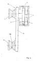
- the device 1 has an up and down adjustable suspension device 3 for the frame, which in particular has at least two, according to FIG. 1 even six or according to FIG. at the same level. It also has a shelf 5 or the like below the suspension device 3 and the support bars 4. for the completed frame 2, over which the support bars 4 protrude approximately horizontally according to FIG. 1.
- the support bars 4 are retractable with respect to the storage surface 5 in their longitudinal direction, which is indicated by dash-dotted lines when the support bars 4 are in the up position.
- the suspension device 3 also has a separating device 6 for the frames 2 carried by it, which is shown in more detail in FIGS. 6 to 8 and described in more detail below.
- the frames 2 as shown in FIGS. 1 to 3, can be placed one behind the other on the storage surface 5 of the device 1 in the manner of index cards, frames of different sizes being able to follow one another, but of course all series of the same size are temporarily stored in series production can.
- these parked frames can now be grasped and lifted by the support bars 4. If the support bars are initially in an upper position above the storage surface 5 in the starting position, they can according to the upper horizontal double arrow Pf 1 withdrawn, then lowered according to the vertical double arrow Pf 2 and now pushed forward approximately horizontally according to the third double arrow Pf 3, whereby they reach the inner openings of the parked frame 2. Then they can be raised again according to the double arrow Pf 2, after which they are in the suspended top position shown in FIG. 2.
- the recognizable oblique position of the support bars 4 in the up position will be explained in the following and serves to feed the frame 2 of the separating device 6 and the transfer device 7 in the simplest possible manner.
- the device 1 has a chassis with wheels 8. It could, however, also be transported by a forklift or other means of conveyance.
- storage would also be conceivable only on one guide rod 9 or, if necessary, also on more than two guide rods 9.
- the guide rods 9 are arranged on an edge of the storage surface 5, while on the opposite edge of this storage surface 5 these stanchions 10 or the like.
- Supports are provided, which can be detachably fastened in order to be able to avoid the support bars 4 which are to be inserted into the frame 2 in accordance with the arrow Pf 3.
- the frames 2 can thus be placed between the guide columns 9 and the stanchions 10 like index cards and stacked one behind the other.
- the vertical guide rods 9 are hollow in cross section and open on one side, namely C-shaped.
- the openings 11 of these C-profiles face each other.
- the suspension device 3 now has for each guide rod 9 a chassis designated as a whole with 12, which is shown in more detail in FIGS. 4 and 5 and has engaging rollers 13 for the guided upward and downward movement in the interior of the C-profile, according to FIG. Fig. 5 a total of four such roles for the different loads caused by the different positions of the support bars 4 once on one side and on the other side of these guide rods 9.
- other horizontal guide rods or the support bars 4 themselves of the suspension device 3 engage on the outside Rollers 14 for horizontal movement.
- the guide rod is hollow and open on one side, but U-shaped, and the chassis 12 engages with rollers 13 on the legs 17 of the guide rod 9 from the inside.
- the escape of the rollers 13 from the opening 11 of the guide rod 9 is prevented by the fact that the second guide rod 9 is arranged mirror-symmetrically to the first and a rigid spacer between two chassis in a manner not shown ensures a constant fixed distance.
- the plate 15 can be pivoted or tilted relative to the actual driving part with the rollers 13 about a horizontal axis 38, which is still to be explained with reference to FIG. 11, about the inclined position of the support bars 4 in FIG to allow their top position.
- the vertical guide rods 9 and the guide device for the suspension device 3 are designed such that, in the uppermost position of the suspension device 3, the support bars 4 according to FIG. 2 and also according to FIGS. 7 can be tilted downwards with their free end so far that the attached frame 2 automatically slide against this end due to the force of gravity, where a stop 16 for this frame 2 is provided on the respective support beam 4 and stands up (cf. before 6 to 8).
- the support bars 4 can be tilted by about 10 ° to 20 ° with respect to a horizontal.
- FIG. 9 shows a possible solution of how this tilting of the support bars 4 is achieved automatically in their up position.
- the guide for the chassis 12 of the guide columns or rods 9 has a correspondingly oblique deviation in its upper end region.
- each C-profile of the guide rod 9 has a partial punching 18 on the legs 17 facing the suspended frame 2, which can be reinforced if necessary and the tilting slope of the support bars 4 runs obliquely from bottom to top towards the outside.
- Fig. 9 it is clear how in this area of the partial punch 18, the entire chassis 12 and thus the associated support beam 4 are tilted because the rollers 13 follow this part cutout 18 which is folded forward, which is due to the weight of the support beam 4 the frame 2 happens.
- an adjusting screw 19 engaging on the guide rod 9 is provided on the upper free leg of the partial punching.
- a stop 20 for the chassis 12 is provided in the guide rod.
- a limit switch could possibly also be provided here.
- the bent-out part 18 of the guide is somewhat curved away from the guide rod 9.
- the chassis 12 preferably have coupled traction elements, in particular chain drives for their upward and downward movement.
- a corresponding drive motor 21 for these chain drives is indicated in FIG. 2.
- an air motor 21 if necessary also an electric motor, which can preferably be stopped under current, can be provided, which can hold the support bars 4 in their up position against the stop 20 while under drive energy. Special mechanical holding devices, which would be conceivable, are therefore unnecessary for the upright position of the support bars 4.
- Fig. 11 shows a preferred solution of how the tipping of the support bars 4 is automatically achieved in their up position.
- the guide rods 9 for the chassis 12 have an incline that is adjustable relative to a pin 40 with respect to their inclination via an arcuate elongated slot 39 41 protrude as a tilting device in the interior of the U-profile and that the plate 15 having the guide rollers 14 can be pivoted about the already mentioned axis 38 against the restoring force of tension springs 42 relative to the carriage or chassis having the guide rollers 13 and that cooperates with the ramp slope 41, has rigidly engaging deflection projection 43.
- the deflection projection 43 and the pivot axis 38 for the plate 15 are arranged laterally at their center in order to provide a sufficiently large engagement distance for the tension springs 42 engaging on a lever arm 44 on the plate 15, the opposite end of which having the rollers 13 Carriage 45 are attached.
- the guide rod 9 can also in its upper region remain undeformed.
- FIGS. 6 to 8 The separating device 6 for the frames 2 raised by the support bars 4 is shown in more detail in FIGS. 6 to 8, FIG. 6 also showing how a separated frame 2 is detected by a transfer device 7.
- a rocker arm 22 is pivotably mounted in each case in the area of the stop 16 for the frames 2 on the support bars 4, which under one end 23 engages under the foremost frame 2 in the area of the stop 16 and - in the exemplary embodiment at its opposite end 24 - is actuated by an actuating device 25, the pivoting path of the lever 22 in the region of the stop 16 corresponding at least to the height of this stop 16, so that the lever 22 moves a frame 2 from the contact position against the stop 16 beyond this, as shown in Fig. 7 u. 8 is indicated. 6 and 7, the side of the stop 16 facing away from the stop surface falls obliquely towards the top of the spar 4, so that the isolated frame 2 can automatically pass on until it can be gripped by the transfer device 7.
- a tappet 26 in particular a pressure-operated tappet or the like, can be used. be provided.
- Fig. 7 it can be clearly seen that the stop 16 is set back relative to the end face 27 of the lever 22, so that this end face 27 in turn forms a stop for the remaining frame 2 as long as the lever 22 with an isolated one Frame 2 is in the lifting position shown in FIG. 7. This can prevent the remaining frames from slipping already during the lifting of the frame 2 to be separated and disturbing the separation process.
- At least one bare and spherical slideway 28 for the frames 2 is arranged on the top of the support bars 4 in the longitudinal direction thereof in order to facilitate their downward sliding on the inclined bar 4 and to make them independent of any drive means.
- a groove 28a that takes this into account can be seen on the rollers 14 in FIG. 4, which encompass the spars somewhat.
- the rocker arm 22 is rocker-like and bent such that two lever arms 29 and 30 enclose an obtuse angle with each other on both sides of the bearing 31, the lever arm 30 facing away from the stop 16 according to the starting position.
- the frames 2 hang horizontally with a frame leg, at least two parallel support bars 4 are provided for each frame 2, each with a stop 16 and a lever 22 for separation.
- Actuation of the lever 22 for lifting a frame 2 expediently takes place against a restoring force, in the exemplary embodiment against a restoring spring 33.
- the lever 22 After the plunger 26 has been retracted, the lever 22 therefore automatically assumes its starting position, with its end face 27 being pivoted back out of the area of the frame 2, so that it reaches up to Stop slipping 16 can.
- the protrusion of the end face 27 with respect to the stop 16 is less than a frame width, so that it is ensured that the lever engages only in the foremost frame resting on the stop 16 and can lift it alone during the next work cycle.
- FIG. 7a A particularly favorable and preferred embodiment of the separating device 6 is shown in FIG. 7a.
- the lever 22 is designed as a one-sided lever, which cooperates in the same way with a plunger 26 and a projection 16 for separating the frames 2, as the pivot lever according to FIG. 7.
- matching parts also have the same reference numbers.
- the angled lever end 30 is missing and instead the spar 4 has a catch projection 46, from which the isolated frame 2 can be removed by means of the hook 32.
- the separating lever 22 can work completely unaffected by an individual frame that may be loaded on it.
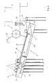
- a second embodiment of the device 1 according to the invention is shown in plan view, which in the essential features and construction details, that is, with respect to the suspension device 3 for the frame 2 with the up and down and back and forth adjustable support bars 4 and the separating device 6 corresponds to the device described above, which can be moved due to the rollers 8.
- the difference in device 1 according to FIG. 10 is that it is stationary as a magazine on a further conveying or further processing device for the frame 2, for example a device for applying sealant to the frame, and a means of conveyance with a receptacle 5 for it the frame 2 in the exemplary embodiment listens to a particularly advantageous trolley 35 which, according to this device 1.
- the receptacle 5 is also formed on the trolley 35 for parking the frames 2 in this device according to FIG. 10, preferably a smooth storage surface on which the frames 2 can in turn be set up in the form of index cards.
- the guide rods 9 have feet 36 at their lower end for their stationary installation, which feet can be anchored on their base.
- a combination of the two illustrated embodiments of devices 1 would of course also be conceivable, in that anchors for stationary installation or castors can be attached to these feet 36.
- the feet 36 project on the guide rods 9 according to FIG. 10 parallel to the support bars 4 and in the direction of the support bars 4 in relation to the guide bars 9, in which the support bars 4 with attached frames 2 are located, in order to better counteract the higher load then occurring to initiate the stand space.
- Fig. 10 makes it clear that the trolley 35 with its chassis and its shelf 5 fits between the feet 36 of the guide rods 9 below the support bars 4. So he can easily in this Be can be retracted richly in order to bring the frame 2 located on it into the area of the support bars 4, which can then pick up the frame in the manner already described, separate it and transfer it to the transfer device 7 or another further device.
- Fig. 10 it is also indicated that the storage surface 5 of the trolley 35 has two side edges 37 and supports for leaning against the parked frame 2 on two opposite side edges 37 arranged transversely to their course when entering under the support bars 4.
- the frames are already oriented in the direction in which they are required for the mounting by the support bars 4 when retracting.
- FIG. 10 these side boundaries 37 are shown only schematically from above. It is expedient if stanchions with intermediate spaces between them are provided as side boundaries 37 of the trolley 35, the intermediate spaces being larger in the lateral direction than the corresponding dimension of the support bars 4. Such stanchions thus form practically comb-like side boundaries, so that the support spars, which are likewise arranged in a comb-like or rake-like manner, can be moved between them, especially upwards, after they have been inserted into the frame openings.
- the stanchion-like side boundaries of the storage surface 5 of the device 1 according to FIG. 1 or of the trolley 35 carry at least one crossbar bridging their spaces, which can rest on a support on the stanchions and in the vertical lifting direction is preferably unpaved.
- the vertical frame legs can be on the Shelf 5 located frames are supported laterally on this rod, on the other hand, there would be no damage when lifting the support bars even if the lifting of this crossbar, which was actually required beforehand, would be forgotten.
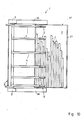
- FIGS. 12 and 13 show the plate 15 tilted by the run-up slope 41 of the guide rod 9 in an inclined position with a supporting bar 4 held by it in a corresponding inclined position for separating the frames of different widths and sizes 2 attached to it. Since these frames with different dimensions have different weights and, under certain circumstances, lie differently on the parallel support bars 4 and thus slightly different frictional forces can arise on the individual bars, with such very differently composed frame packs, deviations from the desired parallel orientation of the frames 2 could occur during the respective slipping on to the separating device. Therefore, in the exemplary embodiment according to FIGS.
- a cross bar 47 engaging behind the frame package and parallel guides 48 are provided for this cross bar 47, which parallel guides 48 are not only parallel to one another, but according to FIG. 12 in Use position also parallel to the spars 4 and at a distance above the upper frame legs of the suspended frame 2, which is smaller than the thickness of this frame between the inside of the frame and the outside of the frame. It can be clearly seen in FIG. 12 that this precludes the possibility that a rear frame 2 may overlap a frame in front of it is pushed, which could happen especially if the rear frame is larger and heavier than the one in front of it.
- the guides 48 can be swiveled upwards in accordance with the arrow Pf 12, especially when the uprights 4 are lowered, ie when they take up the frames, which can be done about the joint 50 with the aid of a working cylinder 49. Thus, with the uprights 4 lowered, the reception of the frames 2 is not hindered by these guides 48.
- the crossbar 47 for the advance movement of the frame 2 can be inclined together with the bars 4, as can be clearly seen in FIG. 12. It can be displaced either by gravity or, if necessary, also by motor force, in the first case simply the weight of the crossbar 47 and its uniform parallel guidance on the parallel guide rods 48 ensure the undisturbed advancement of the frames 2, the guide rods 48 preventing in an advantageous manner, that a rear frame 2 climbs over a front one.
- FIGS. 14 and 15 A modified embodiment for the advance of the frame 2 can be seen in FIGS. 14 and 15.
- the frame 2 on the bars 4 are provided with endless belts 51, the deflection roller 52 with the drive motor 53 of which can be seen above all in FIG.
- This drive is located on the side of the bars 4 facing away from the separating device, beyond the guide rod 9.
- the frames 2 can rest with their upper frame legs according to FIG. 14.
- the endless belts 51 of the support bars 4 are driven synchronously because they have the common driven deflection roller 52.
- Fig. 15 shows again clearly that the frame 2 of a frame package can have very different dimensions and thus their support on the support bars can be different, which is why such mechanical feed aids for the uniform parallel feed of these different frames are advantageous.
Landscapes
- Engineering & Computer Science (AREA)
- Mechanical Engineering (AREA)
- Chemical & Material Sciences (AREA)
- Combustion & Propulsion (AREA)
- Transportation (AREA)
- Civil Engineering (AREA)
- Structural Engineering (AREA)
- Warehouses Or Storage Devices (AREA)
- Securing Of Glass Panes Or The Like (AREA)
- Packaging Frangible Articles (AREA)
Priority Applications (1)
| Application Number | Priority Date | Filing Date | Title |
|---|---|---|---|
| AT87112863T ATE54716T1 (de) | 1986-09-23 | 1987-09-03 | Vorrichtung zum speichern von abstandhalterrahmen fuer isolierglasscheiben. |
Applications Claiming Priority (2)
| Application Number | Priority Date | Filing Date | Title |
|---|---|---|---|
| DE3632282A DE3632282C1 (de) | 1986-09-23 | 1986-09-23 | Vorrichtung zum Speichern von Abstandhalterrahmen fuer Isolierglasscheiben |
| DE3632282 | 1986-09-23 |
Publications (3)
| Publication Number | Publication Date |
|---|---|
| EP0261471A2 true EP0261471A2 (fr) | 1988-03-30 |
| EP0261471A3 EP0261471A3 (en) | 1989-01-04 |
| EP0261471B1 EP0261471B1 (fr) | 1990-07-18 |
Family
ID=6310142
Family Applications (1)
| Application Number | Title | Priority Date | Filing Date |
|---|---|---|---|
| EP87112863A Expired - Lifetime EP0261471B1 (fr) | 1986-09-23 | 1987-09-03 | Dispositif d'emmagasinage de cadres espaceurs pour vitrages isolants |
Country Status (3)
| Country | Link |
|---|---|
| EP (1) | EP0261471B1 (fr) |
| AT (1) | ATE54716T1 (fr) |
| DE (2) | DE3632282C1 (fr) |
Cited By (3)
| Publication number | Priority date | Publication date | Assignee | Title |
|---|---|---|---|---|
| CN107985445A (zh) * | 2017-12-29 | 2018-05-04 | 南阳淅减汽车减振器有限公司 | 一种汽车减震器贮油缸总成转运装置 |
| CN117468840A (zh) * | 2023-12-25 | 2024-01-30 | 福建省泉州亘重工贸有限公司 | 一种隔音保暖的装配式铝合金门窗及其装配方法 |
| AT527939B1 (de) * | 2024-08-05 | 2025-08-15 | Lisec Austria Gmbh | Rolle |
Families Citing this family (3)
| Publication number | Priority date | Publication date | Assignee | Title |
|---|---|---|---|---|
| AT391682B (de) * | 1987-10-05 | 1990-11-12 | Lisec Peter | Anlage zum foerdern von abstandhalterrahmen fuer isolierglas |
| DE3842082C1 (fr) * | 1988-12-14 | 1990-05-23 | Hermann Wiegand Gmbh, 6419 Rasdorf, De | |
| DE4438502C1 (de) | 1994-10-28 | 1996-02-08 | Fr Xaver Bayer Isolierglasfabr | Übergabevorrichtung für Abstandhalterrahmen |
Family Cites Families (10)
| Publication number | Priority date | Publication date | Assignee | Title |
|---|---|---|---|---|
| DE147417C (fr) * | ||||
| US3101852A (en) * | 1960-06-14 | 1963-08-27 | Pearne And Lacy Machine Compan | Rack unloader |
| FR1405317A (fr) * | 1964-05-26 | 1965-07-09 | Glaces De Boussois | Appareil pour la manutention, le transport et le stockage d'une matière en feuilles |
| US3799318A (en) * | 1971-10-04 | 1974-03-26 | Western Automation Corp | Conveyor loading apparatus |
| US3937329A (en) * | 1974-08-12 | 1976-02-10 | Cobbledick-Kibbe Glass Company | Sheet glass supporting rack |
| FR2287278A1 (fr) * | 1974-10-10 | 1976-05-07 | Saint Gobain | Procede et dispositif pour l'enduction des tranches d'un vitrage multiple |
| DE2712651C2 (de) * | 1977-03-23 | 1978-11-23 | Karl 7531 Neuhausen Lenhardt | Rahmenauflegestation in einer Anlage zum Zusammenbau von Isolierglas |
| IT7821840V0 (it) * | 1978-05-12 | 1978-05-12 | Tecnologico Italiano S A G S P | Dispositivo automatico per impilare, rispettivamente disimpilare pezzi a forma di pannello. |
| DE3221986A1 (de) * | 1982-06-11 | 1983-12-15 | Fr. Xaver Bayer Isolierglasfabrik Kg, 7807 Elzach | Maschine zum herstellen eines abstandhaltenden innenrahmens fuer eine isolierglasscheibe |
| AT385258B (de) * | 1983-09-05 | 1988-03-10 | Lisec Peter | Vorrichtung zum foerdern von tafel- oder rahmenfoermigen bauteilen, insbesondere von isolierglasrohlingen |
-
1986
- 1986-09-23 DE DE3632282A patent/DE3632282C1/de not_active Expired
-
1987
- 1987-09-03 AT AT87112863T patent/ATE54716T1/de not_active IP Right Cessation
- 1987-09-03 DE DE8787112863T patent/DE3763787D1/de not_active Expired - Fee Related
- 1987-09-03 EP EP87112863A patent/EP0261471B1/fr not_active Expired - Lifetime
Cited By (6)
| Publication number | Priority date | Publication date | Assignee | Title |
|---|---|---|---|---|
| CN107985445A (zh) * | 2017-12-29 | 2018-05-04 | 南阳淅减汽车减振器有限公司 | 一种汽车减震器贮油缸总成转运装置 |
| CN117468840A (zh) * | 2023-12-25 | 2024-01-30 | 福建省泉州亘重工贸有限公司 | 一种隔音保暖的装配式铝合金门窗及其装配方法 |
| CN117468840B (zh) * | 2023-12-25 | 2024-03-08 | 福建省泉州亘重工贸有限公司 | 一种隔音保暖的装配式铝合金门窗及其装配方法 |
| AT527939B1 (de) * | 2024-08-05 | 2025-08-15 | Lisec Austria Gmbh | Rolle |
| AT527939A4 (de) * | 2024-08-05 | 2025-08-15 | Lisec Austria Gmbh | Rolle |
| EP4691949A1 (fr) | 2024-08-05 | 2026-02-11 | LISEC Austria GmbH | Rouleau |
Also Published As
| Publication number | Publication date |
|---|---|
| ATE54716T1 (de) | 1990-08-15 |
| EP0261471A3 (en) | 1989-01-04 |
| DE3763787D1 (de) | 1990-08-23 |
| DE3632282C1 (de) | 1988-02-11 |
| EP0261471B1 (fr) | 1990-07-18 |
Similar Documents
| Publication | Publication Date | Title |
|---|---|---|
| DE2130968C2 (de) | Vorrichtung zum Verladen einer Fracht in ein Flugzeug5 | |
| AT394987B (de) | Vorrichtung zum sortieren von glastafelzuschnitten | |
| DE2516455C3 (de) | Vorrichtung zum Be- und Entladen von Stückgütern | |
| EP0675060B1 (fr) | Dispositif pour charger et décharger des objets en forme de plaques | |
| DE19636470C2 (de) | Vorrichtung zum Handhaben von Glasscheiben | |
| AT16353U1 (de) | Transporttasche sowie Verfahren zum Befüllen und Entleeren einer solchen Transporttasche | |
| DE3109174A1 (de) | Ausschleusvorrichtung fuer eine foerderbahn | |
| EP0132635B1 (fr) | Dispositif de chargement pour objets élongés | |
| DE19641860C2 (de) | Vorrichtung zum Umsetzen von Isolierglasscheiben | |
| DE2035952A1 (de) | Anordnung zum selbsttätigen und einzel nen Überfuhren einer Mehrzahl von Lasten in einzelne Gefache | |
| DE3107437A1 (de) | Einrichtung zum beschicken eines werkzeugmaschinenauflagetisches | |
| EP0261471B1 (fr) | Dispositif d'emmagasinage de cadres espaceurs pour vitrages isolants | |
| DE3225280A1 (de) | Werkstueck-beschickungseinrichtung | |
| DE4231103A1 (de) | Verfahren zum Transport einer flexographischen Druckplatte durch eine Bearbeitungsvorrichtung und Vorrichtung zur Herstellung flexographischer Druckplatten | |
| EP1389597B1 (fr) | Méthode et dispositif pour dépiler une pile d'articles disposés en plusieurs couches horizontales | |
| EP0038432B1 (fr) | Dispositif de désempilage de piles, notamment constituées de pièces de bois allongées | |
| DE19948574A1 (de) | Einrichtung zum Vereinzeln und Ausschleusen von in einer Reihe auf einer Rollenbahn abgelegten Stückgütern | |
| EP0470538B1 (fr) | Rayonnage pour le stockage d'écarteurs profilés pour vitres isolantes | |
| DE1981789U (de) | Vorrichtung zum stapeln von hoelzern, rahmen und platten in holzbearbeitungswerkstaetten. | |
| DE69504837T2 (de) | Eine magazinanordnung | |
| DE3336109A1 (de) | Vorrichtung zum stapeln, transport und befuellen von behaeltern | |
| DE2601000C3 (de) | Durchlaufkanal für Kommissionier-Durchlauflager | |
| DE2230328A1 (de) | Behaelter-fahrzeug | |
| DE202005014323U1 (de) | Vorrichtung zum Stapeln von Dachpfannen | |
| DE2944887C2 (de) | Vorrichtung zum Beladen von Paletten mit Stückgütern |
Legal Events
| Date | Code | Title | Description |
|---|---|---|---|
| PUAI | Public reference made under article 153(3) epc to a published international application that has entered the european phase |
Free format text: ORIGINAL CODE: 0009012 |
|
| AK | Designated contracting states |
Kind code of ref document: A2 Designated state(s): AT BE CH DE FR GB IT LI NL |
|
| PUAL | Search report despatched |
Free format text: ORIGINAL CODE: 0009013 |
|
| AK | Designated contracting states |
Kind code of ref document: A3 Designated state(s): AT BE CH DE FR GB IT LI NL |
|
| 17P | Request for examination filed |
Effective date: 19890114 |
|
| 17Q | First examination report despatched |
Effective date: 19890808 |
|
| GRAA | (expected) grant |
Free format text: ORIGINAL CODE: 0009210 |
|
| AK | Designated contracting states |
Kind code of ref document: B1 Designated state(s): AT BE CH DE FR GB IT LI NL |
|
| PG25 | Lapsed in a contracting state [announced via postgrant information from national office to epo] |
Ref country code: IT Free format text: LAPSE BECAUSE OF FAILURE TO SUBMIT A TRANSLATION OF THE DESCRIPTION OR TO PAY THE FEE WITHIN THE PRE;WARNING: LAPSES OF ITALIAN PATENTS WITH EFFECTIVE DATE BEFORE 2007 MAY HAVE OCCURRED AT ANY TIME BEFORE 2007. THE CORRECT EFFECTIVE DATE MAY BE DIFFERENT FROM THE ONE RECORDED.SCRIBED TIME-LIMIT Effective date: 19900718 Ref country code: NL Effective date: 19900718 Ref country code: BE Effective date: 19900718 Ref country code: GB Effective date: 19900718 Ref country code: FR Effective date: 19900718 |
|
| REF | Corresponds to: |
Ref document number: 54716 Country of ref document: AT Date of ref document: 19900815 Kind code of ref document: T |
|
| REF | Corresponds to: |
Ref document number: 3763787 Country of ref document: DE Date of ref document: 19900823 |
|
| EN | Fr: translation not filed | ||
| NLV1 | Nl: lapsed or annulled due to failure to fulfill the requirements of art. 29p and 29m of the patents act | ||
| GBV | Gb: ep patent (uk) treated as always having been void in accordance with gb section 77(7)/1977 [no translation filed] | ||
| PLBE | No opposition filed within time limit |
Free format text: ORIGINAL CODE: 0009261 |
|
| STAA | Information on the status of an ep patent application or granted ep patent |
Free format text: STATUS: NO OPPOSITION FILED WITHIN TIME LIMIT |
|
| 26N | No opposition filed | ||
| PGFP | Annual fee paid to national office [announced via postgrant information from national office to epo] |
Ref country code: GR Payment date: 19930730 Year of fee payment: 7 |
|
| PGFP | Annual fee paid to national office [announced via postgrant information from national office to epo] |
Ref country code: CH Payment date: 19941010 Year of fee payment: 8 |
|
| PG25 | Lapsed in a contracting state [announced via postgrant information from national office to epo] |
Ref country code: LI Effective date: 19950930 Ref country code: CH Effective date: 19950930 |
|
| PGFP | Annual fee paid to national office [announced via postgrant information from national office to epo] |
Ref country code: AT Payment date: 19951031 Year of fee payment: 9 |
|
| REG | Reference to a national code |
Ref country code: CH Ref legal event code: PL |
|
| PGFP | Annual fee paid to national office [announced via postgrant information from national office to epo] |
Ref country code: DE Payment date: 19960724 Year of fee payment: 10 |
|
| PG25 | Lapsed in a contracting state [announced via postgrant information from national office to epo] |
Ref country code: AT Effective date: 19960903 |
|
| PG25 | Lapsed in a contracting state [announced via postgrant information from national office to epo] |
Ref country code: DE Free format text: LAPSE BECAUSE OF NON-PAYMENT OF DUE FEES Effective date: 19980603 |