EP0263199A1 - Compresseur à membrane - Google Patents
Compresseur à membrane Download PDFInfo
- Publication number
- EP0263199A1 EP0263199A1 EP86114036A EP86114036A EP0263199A1 EP 0263199 A1 EP0263199 A1 EP 0263199A1 EP 86114036 A EP86114036 A EP 86114036A EP 86114036 A EP86114036 A EP 86114036A EP 0263199 A1 EP0263199 A1 EP 0263199A1
- Authority
- EP
- European Patent Office
- Prior art keywords
- diaphragm
- membrane
- diameter
- housing part
- plate
- Prior art date
- Legal status (The legal status is an assumption and is not a legal conclusion. Google has not performed a legal analysis and makes no representation as to the accuracy of the status listed.)
- Granted
Links
Images

Classifications
-
- F—MECHANICAL ENGINEERING; LIGHTING; HEATING; WEAPONS; BLASTING
- F04—POSITIVE - DISPLACEMENT MACHINES FOR LIQUIDS; PUMPS FOR LIQUIDS OR ELASTIC FLUIDS
- F04B—POSITIVE-DISPLACEMENT MACHINES FOR LIQUIDS; PUMPS
- F04B45/00—Pumps or pumping installations having flexible working members and specially adapted for elastic fluids
- F04B45/04—Pumps or pumping installations having flexible working members and specially adapted for elastic fluids having plate-like flexible members, e.g. diaphragms
Definitions
- the invention relates to a membrane compressor with a compressor housing, which is composed of a lower housing part and an upper housing part.
- a flexible membrane is firmly clamped with its edge between the lower housing part and the upper housing part.
- the membrane is inserted between a lower membrane plate and an upper membrane plate, the membrane plates having a smaller diameter than the membrane, so that the membrane remains flexible in the area of its edge.
- a connecting rod driven by an eccentric is connected to the diaphragm and the diaphragm plates in order to set them together in a stroke movement.
- the diaphragm, the upper diaphragm plate and the upper housing part delimit a working area, the upper diaphragm plate reaching almost to the upper inner wall of the upper part of the housing at top dead center and an annular channel-shaped dead space remaining in the area of the edge of the diaphragm. It there is also an inlet and an outlet for the medium to be compressed, which are connected to the working space.
- a piston chamber for receiving the diaphragm and the diaphragm plate in the bottom dead center.
- Membrane compressors of this type are used to convey or compress liquid or gaseous media.
- the drive power is between 1 watt and approx. 3 kw, so that such membrane compressors have a wide range of applications.
- smaller diaphragm compressors with drive powers of up to approximately 200 watts are often used as drive or actuation units for devices in the medical field due to their simple construction. For example, they serve as pumps for inhalers.
- the design goal of the membrane compressors currently on the market is to cover the largest possible area of application, which means that the highest possible pressure or the highest possible throughput of the flowing medium should be achieved with the available drive power.
- Conventional diaphragm compressors therefore achieve relatively high, maximum pressures that can be generated even with low drive power. This is expressed in a pressure-volume flow characteristic curve that rises steeply to high pressure values. The maximum pressure is reached with a volume flow of zero. In practice, this corresponds to the case that the outlet of the compressor is shut off, for example by locking.
- the pressure built up inside the work area reaches up to several times the normal operating pressure.
- Membrane compressor and devices connected to them must be designed for these high, possible pressure values, although normally no such loads are provided at all.
- connecting hoses and associated hose connections must be designed to be correspondingly complex in order to be able to cope with the possible maximum pressure.
- special connection techniques such as hose clamps are necessary.
- Such elaborate, constructive measures to protect against excess pressure are certainly to be represented when it comes to devices that are built as individual pieces or in small series. In the case of large series devices that are under strong price pressure, such additional expenses represent a considerable cost factor only for safety reasons, which can no longer be accepted.
- a membrane compressor of the type mentioned at the beginning It is solved in that the working chamber formed in the upper housing part of the compressor housing has a larger diameter than the piston chamber in the lower housing part, in that the diameter of the lower one Membrane plate is noticeably smaller than the diameter of the piston chamber, so that an annular gap remains between the lower membrane plate and the opposite inner wall of the lower housing part, and in that the diameter of the upper membrane plate corresponds at least to that of the lower membrane plate.
- This design of the diaphragm compressor according to the invention results in a dead space when the top dead center is reached, which is filled with compressed medium.
- This dead space immediately above the clamped edge of the membrane concentrically surrounds the upper diaphragm plate and is shifted outwards compared to conventional diaphragm compressors. Because the lower diaphragm plate does not reach all the way to the inner edge of the piston space in the lower housing part, the non-stiffened edge area of the flexible diaphragm is enlarged. When the maximum possible pressure is reached, for example when the outlet is blocked, in the dead space mentioned, the membrane can move downward into the annular gap between the lower membrane plate and the edge of the lower housing part; it thus represents overpressure protection.
- the diameter of the working space is approximately 5 to 15 percent larger than the diameter of the piston space.
- the diameter of the lower diaphragm plate is approximately 3 to 10 percent smaller than the diameter of the piston chamber.
- the diameter of the upper membrane plate is larger than the diameter of the lower membrane plate. This results in an increased compression ratio, so that the eccentricity of the driving eccentric can be reduced. Due to the reduced stroke, the edge areas of the membrane that are subjected to bending are less stressed, which leads to an increase in the membrane service life and also in the other moving components.
- a circumferential groove is expediently provided in the upper housing part, which receives the edge of the membrane. In this groove, the elastic membrane is held in its intended position in the pressed state.
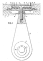
- the membrane compressor shown in Fig. 1 has a compressor housing (1) which is composed of a lower housing part (2) and an upper housing part (3).
- a circumferential groove (4) is provided in the housing upper part (3), which receives a membrane (5) made of a flexible material, for example rubber, with its edge (6).
- the membrane (5) is held in position within the groove (4) by pressing between the lower housing part (2) and the upper housing part (3).
- a lower membrane plate (7) or an upper membrane plate (8) lie on both sides of the membrane (5).
- the two diaphragm plates (7, 8) are torsionally rigid, so that the interposed diaphragm (5) remains elastically deformable only in the area of its edge (6).
- the diaphragm compressor is driven by a motor (not shown).
- An eccentric (10) is slid onto its motor shaft (9). The eccentric rotary movement is transmitted to a connecting rod (12) via a bearing (11).
- the free end of the connecting rod (12) is connected to the lower diaphragm plate (7), the upper diaphragm plate (8) and the interposed diaphragm (5) via an intermediate disc (13).
- a countersunk screw (14) ensures that the diaphragm plate (7, 8) and diaphragm (5) are securely attached to the connecting rod (12).
- a working space (15) is delimited by the uncovered areas of the membrane (5), the upper membrane plate (8) and the upper housing part (3).
- the medium to be compressed for example gas
- enters the working space (15) which it leaves through an outlet (17) after compression.
- a piston chamber (18) is divided by the membrane (5) from the working chamber (15), which is essentially embedded in the lower housing part (2). At the bottom dead center, this piston chamber (18) receives the diaphragm (5) and the diaphragm plate (7, 8).
- This dead space (19) denotes the dead space in which compressed medium remains when the upper diaphragm plate (8) comes to rest on the flat inner wall of the upper housing part (3) up to a gap of approx. 0.1 mm at the top dead center.
- This dead space (19) has the shape of an annular channel and is located in the region of the edge (6) of the membrane (5).
- Those delimiting lines of the lower diaphragm plate (7), the upper diaphragm plate (8) and the upper housing part (3) are shown in dashed lines, which run differently in a conventional diaphragm compressor than in the diaphragm compressor according to the invention shown here is.
- the upper diaphragm plate has a much smaller diameter than the lower diaphragm plate (7), while according to the invention the respective diameters are the same.
- the diameter of the working chamber 15 is larger than the diameter of the piston chamber 18; in conventional compressors, the respective diameters are approximately the same size.
- the increase in the diameter of the upper diaphragm plate (8) and the working space (15) in the upper housing part (3) in the same direction leads to a displacement of the dead space (19) radially outwards in comparison to conventional compressors (see dashed lines). This displacement of the dead space (19) to the outside is simultaneously associated with an increase in its volume by approximately 40 percent.
- the diameter of the lower membrane plate (7) is enlarged far into the area of the edge (6) of the membrane (5). If the pressure of the compressed medium in the dead space (19) reaches a certain critical value, the membrane (5) can move downwards into the annular gap (20) between the lower housing part (2) and the lower membrane plate (7), which automatically causes a pressure limitation .
- Fig. 2 illustrates the effects of the design changes made in the diaphragm compressor according to the invention compared to a conventional compressor.
- the pressure P built up in the working space (15) (cf. FIG. 1) is above the volume throughput a flowing medium, which flows from the inlet (16) to the outlet (17), applied.
- the characteristic curve K h of a conventional diaphragm compressor is drawn in, as can be seen in FIG. results. What is striking is the sharp increase in pressure P with a decrease in the flowing volume per unit of time. In the extreme case, the volume flow is equal to 0, which corresponds, for example, to the operation of the compressor with the outlet (17) closed. The pressure P rises to the maximum possible value. This pressure peak, which is possible at any time in conventional diaphragm compressors, must be taken into account; For example, special hose connections are required to connect a hose to the outlet (17). Because of the steepness of the characteristic curve K h , there is also a large scattering range SB h in the characteristic curve field. While the operating point B is shifted to a tolerable extent on a vertical parallel to the ordinate axis up or down, this spreading range has a much stronger effect with regard to the maximum pressure.
- the diaphragm compressor according to the invention has a characteristic curve K e , which likewise passes through the same operating point B.
- the characteristic curve K e is substantially flatter, namely almost straight.
- the maximum pressure that can be generated by the compressor is considerably lower; the spreading range SB e to be taken into account is correspondingly narrower.
- the same operating point B can be set with the membrane compressor according to the invention, because of the the pressure-volume flow characteristic curve K e, which runs much flatter, dangerous pressure peaks no longer occur even when the outlet (17) is completely shut off.
Landscapes
- Engineering & Computer Science (AREA)
- Mechanical Engineering (AREA)
- General Engineering & Computer Science (AREA)
- Reciprocating Pumps (AREA)
- Diaphragms And Bellows (AREA)
- Separation Using Semi-Permeable Membranes (AREA)
- Compressor (AREA)
Priority Applications (4)
| Application Number | Priority Date | Filing Date | Title |
|---|---|---|---|
| EP86114036A EP0263199B2 (fr) | 1986-10-10 | 1986-10-10 | Compresseur à membrane |
| AT86114036T ATE65299T1 (de) | 1986-10-10 | 1986-10-10 | Membrankompressor. |
| DE8686114036T DE3680339D1 (de) | 1986-10-10 | 1986-10-10 | Membrankompressor. |
| DE8626979U DE8626979U1 (de) | 1986-10-10 | 1986-10-10 | Membrankompressor |
Applications Claiming Priority (1)
| Application Number | Priority Date | Filing Date | Title |
|---|---|---|---|
| EP86114036A EP0263199B2 (fr) | 1986-10-10 | 1986-10-10 | Compresseur à membrane |
Publications (3)
| Publication Number | Publication Date |
|---|---|
| EP0263199A1 true EP0263199A1 (fr) | 1988-04-13 |
| EP0263199B1 EP0263199B1 (fr) | 1991-07-17 |
| EP0263199B2 EP0263199B2 (fr) | 1995-10-04 |
Family
ID=8195489
Family Applications (1)
| Application Number | Title | Priority Date | Filing Date |
|---|---|---|---|
| EP86114036A Expired - Lifetime EP0263199B2 (fr) | 1986-10-10 | 1986-10-10 | Compresseur à membrane |
Country Status (3)
| Country | Link |
|---|---|
| EP (1) | EP0263199B2 (fr) |
| AT (1) | ATE65299T1 (fr) |
| DE (1) | DE3680339D1 (fr) |
Citations (4)
| Publication number | Priority date | Publication date | Assignee | Title |
|---|---|---|---|---|
| FR392356A (fr) * | 1908-07-16 | 1908-11-25 | Martin Falk | Perfectionnements apportés aux pompes à vide à membrane |
| FR744350A (fr) * | 1933-04-14 | |||
| US3947156A (en) * | 1972-03-08 | 1976-03-30 | Erich Becker | Diaphragm pump, particularly for the generation of vacuum |
| DE8626979U1 (de) * | 1986-10-10 | 1986-11-20 | Brugger, Stephan, Dipl.-Wirtsch.-Ing.(FH), 8137 Berg | Membrankompressor |
-
1986
- 1986-10-10 DE DE8686114036T patent/DE3680339D1/de not_active Expired - Fee Related
- 1986-10-10 AT AT86114036T patent/ATE65299T1/de active
- 1986-10-10 EP EP86114036A patent/EP0263199B2/fr not_active Expired - Lifetime
Patent Citations (4)
| Publication number | Priority date | Publication date | Assignee | Title |
|---|---|---|---|---|
| FR744350A (fr) * | 1933-04-14 | |||
| FR392356A (fr) * | 1908-07-16 | 1908-11-25 | Martin Falk | Perfectionnements apportés aux pompes à vide à membrane |
| US3947156A (en) * | 1972-03-08 | 1976-03-30 | Erich Becker | Diaphragm pump, particularly for the generation of vacuum |
| DE8626979U1 (de) * | 1986-10-10 | 1986-11-20 | Brugger, Stephan, Dipl.-Wirtsch.-Ing.(FH), 8137 Berg | Membrankompressor |
Also Published As
| Publication number | Publication date |
|---|---|
| ATE65299T1 (de) | 1991-08-15 |
| DE3680339D1 (de) | 1991-08-22 |
| EP0263199B1 (fr) | 1991-07-17 |
| EP0263199B2 (fr) | 1995-10-04 |
Similar Documents
| Publication | Publication Date | Title |
|---|---|---|
| DE4203677C2 (de) | Spiralverdichter | |
| DE19603109C2 (de) | Kolben-Kältemittelkompressor mit verbesserter Dichtfunktion | |
| EP3482076B1 (fr) | Couvercle de tête de cylindre pour un compresseur de réfrigérant | |
| DE2308265A1 (de) | Rotations- bzw. drehkolbenverdichter anlage mit oelkreislauf und ventilanordnungen | |
| DE19530210C2 (de) | Taumelscheibenverdichter | |
| DE4333143A1 (de) | Kältemittelkompressor mit hin- und herbeweglichen Kolben | |
| DE102005055628A1 (de) | Linearer Kompressor | |
| DE19519763C2 (de) | Inhalationsgerätekompressor mit verbessertem Membransatz | |
| EP4004370B1 (fr) | Dispositif de soupape pour un compresseur à piston | |
| DE3633644A1 (de) | Kompressor mit variabler foerderleistung | |
| EP4155542A1 (fr) | Compresseur haute pression et système comprenant un compresseur haute pression | |
| DE3700919C2 (fr) | ||
| EP2357115B2 (fr) | Compresseur à air comprimé et procédé de fonctionnement d'un compresseur à air comprimé | |
| DE1922269A1 (de) | Summenleistungsregler | |
| EP0263199A1 (fr) | Compresseur à membrane | |
| DE8626979U1 (de) | Membrankompressor | |
| EP2885540A1 (fr) | Compresseur | |
| WO2004025123A1 (fr) | Pompe pour appareil de nettoyage haute pression | |
| EP0211096B1 (fr) | Réglage de puissance ou limitation de couple | |
| CH704934B1 (de) | Vakuumventil. | |
| AT3212U1 (de) | Radialkolbenpumpe | |
| EP1387957A1 (fr) | Machine a pistons elevateurs dotee d'une articulation | |
| DE3704588C2 (fr) | ||
| EP3039281A1 (fr) | Pompe à carburant haute pression et dispositif agissant sur la pression | |
| EP0375848B1 (fr) | Pompe de dosage |
Legal Events
| Date | Code | Title | Description |
|---|---|---|---|
| PUAI | Public reference made under article 153(3) epc to a published international application that has entered the european phase |
Free format text: ORIGINAL CODE: 0009012 |
|
| AK | Designated contracting states |
Kind code of ref document: A1 Designated state(s): AT BE CH DE ES FR GB GR IT LI LU NL SE |
|
| 17P | Request for examination filed |
Effective date: 19880621 |
|
| 17Q | First examination report despatched |
Effective date: 19881202 |
|
| GRAA | (expected) grant |
Free format text: ORIGINAL CODE: 0009210 |
|
| AK | Designated contracting states |
Kind code of ref document: B1 Designated state(s): AT BE CH DE ES FR GB GR IT LI LU NL SE |
|
| PG25 | Lapsed in a contracting state [announced via postgrant information from national office to epo] |
Ref country code: IT Free format text: LAPSE BECAUSE OF FAILURE TO SUBMIT A TRANSLATION OF THE DESCRIPTION OR TO PAY THE FEE WITHIN THE PRE;WARNING: LAPSES OF ITALIAN PATENTS WITH EFFECTIVE DATE BEFORE 2007 MAY HAVE OCCURRED AT ANY TIME BEFORE 2007. THE CORRECT EFFECTIVE DATE MAY BE DIFFERENT FROM THE ONE RECORDED.SCRIBED TIME-LIMIT Effective date: 19910717 Ref country code: GR Free format text: LAPSE BECAUSE OF FAILURE TO SUBMIT A TRANSLATION OF THE DESCRIPTION OR TO PAY THE FEE WITHIN THE PRESCRIBED TIME-LIMIT Effective date: 19910717 Ref country code: FR Effective date: 19910717 Ref country code: GB Effective date: 19910717 Ref country code: SE Effective date: 19910717 |
|
| REF | Corresponds to: |
Ref document number: 65299 Country of ref document: AT Date of ref document: 19910815 Kind code of ref document: T |
|
| REF | Corresponds to: |
Ref document number: 3680339 Country of ref document: DE Date of ref document: 19910822 |
|
| PG25 | Lapsed in a contracting state [announced via postgrant information from national office to epo] |
Ref country code: AT Effective date: 19911010 |
|
| PG25 | Lapsed in a contracting state [announced via postgrant information from national office to epo] |
Ref country code: LU Free format text: LAPSE BECAUSE OF NON-PAYMENT OF DUE FEES Effective date: 19911031 Ref country code: BE Effective date: 19911031 Ref country code: LI Effective date: 19911031 Ref country code: CH Effective date: 19911031 |
|
| EN | Fr: translation not filed | ||
| GBV | Gb: ep patent (uk) treated as always having been void in accordance with gb section 77(7)/1977 [no translation filed] | ||
| PLBI | Opposition filed |
Free format text: ORIGINAL CODE: 0009260 |
|
| BERE | Be: lapsed |
Owner name: BRUGGER STEPHAN Effective date: 19911031 |
|
| PG25 | Lapsed in a contracting state [announced via postgrant information from national office to epo] |
Ref country code: NL Effective date: 19920501 |
|
| PLBI | Opposition filed |
Free format text: ORIGINAL CODE: 0009260 |
|
| 26 | Opposition filed |
Opponent name: KNF- NEUBERGER GMBH Effective date: 19920331 |
|
| NLV4 | Nl: lapsed or anulled due to non-payment of the annual fee | ||
| 26 | Opposition filed |
Opponent name: KNF- NEUBERGER GMBH Effective date: 19920331 Opponent name: VEIT GMBH & CO. Effective date: 19920416 |
|
| REG | Reference to a national code |
Ref country code: CH Ref legal event code: PL |
|
| PUAH | Patent maintained in amended form |
Free format text: ORIGINAL CODE: 0009272 |
|
| STAA | Information on the status of an ep patent application or granted ep patent |
Free format text: STATUS: PATENT MAINTAINED AS AMENDED |
|
| 27A | Patent maintained in amended form |
Effective date: 19951004 |
|
| AK | Designated contracting states |
Kind code of ref document: B2 Designated state(s): AT BE CH DE ES FR GB GR IT LI LU NL SE |
|
| REG | Reference to a national code |
Ref country code: CH Ref legal event code: AEN Free format text: AUFRECHTERHALTUNG DES PATENTES IN GEAENDERTER FORM |
|
| PG25 | Lapsed in a contracting state [announced via postgrant information from national office to epo] |
Ref country code: ES Free format text: LAPSE BECAUSE OF FAILURE TO SUBMIT A TRANSLATION OF THE DESCRIPTION OR TO PAY THE FEE WITHIN THE PRESCRIBED TIME-LIMIT Effective date: 19960115 |
|
| EN | Fr: translation not filed | ||
| PGFP | Annual fee paid to national office [announced via postgrant information from national office to epo] |
Ref country code: DE Payment date: 19991124 Year of fee payment: 14 |
|
| PG25 | Lapsed in a contracting state [announced via postgrant information from national office to epo] |
Ref country code: DE Free format text: LAPSE BECAUSE OF NON-PAYMENT OF DUE FEES Effective date: 20010703 |
|
| PG25 | Lapsed in a contracting state [announced via postgrant information from national office to epo] |
Ref country code: ES Free format text: LAPSE BECAUSE OF FAILURE TO SUBMIT A TRANSLATION OF THE DESCRIPTION OR TO PAY THE FEE WITHIN THE PRESCRIBED TIME-LIMIT Effective date: 19911031 |