EP0264520A1 - Nivellierschuh - Google Patents
Nivellierschuh Download PDFInfo
- Publication number
- EP0264520A1 EP0264520A1 EP87101282A EP87101282A EP0264520A1 EP 0264520 A1 EP0264520 A1 EP 0264520A1 EP 87101282 A EP87101282 A EP 87101282A EP 87101282 A EP87101282 A EP 87101282A EP 0264520 A1 EP0264520 A1 EP 0264520A1
- Authority
- EP
- European Patent Office
- Prior art keywords
- leveling shoe
- spring element
- shoe according
- spring
- leveling
- Prior art date
- Legal status (The legal status is an assumption and is not a legal conclusion. Google has not performed a legal analysis and makes no representation as to the accuracy of the status listed.)
- Granted
Links
- 238000012423 maintenance Methods 0.000 claims description 2
- 230000036316 preload Effects 0.000 claims description 2
- 238000004519 manufacturing process Methods 0.000 description 3
- 230000015572 biosynthetic process Effects 0.000 description 1
- 230000000903 blocking effect Effects 0.000 description 1
- 230000006835 compression Effects 0.000 description 1
- 238000007906 compression Methods 0.000 description 1
- 238000013016 damping Methods 0.000 description 1
- 230000007812 deficiency Effects 0.000 description 1
- 238000003780 insertion Methods 0.000 description 1
- 230000037431 insertion Effects 0.000 description 1
- 238000009434 installation Methods 0.000 description 1
- 230000001020 rhythmical effect Effects 0.000 description 1
- 210000001550 testis Anatomy 0.000 description 1
- 238000004804 winding Methods 0.000 description 1
Images

Classifications
-
- F—MECHANICAL ENGINEERING; LIGHTING; HEATING; WEAPONS; BLASTING
- F16—ENGINEERING ELEMENTS AND UNITS; GENERAL MEASURES FOR PRODUCING AND MAINTAINING EFFECTIVE FUNCTIONING OF MACHINES OR INSTALLATIONS; THERMAL INSULATION IN GENERAL
- F16M—FRAMES, CASINGS OR BEDS OF ENGINES, MACHINES OR APPARATUS, NOT SPECIFIC TO ENGINES, MACHINES OR APPARATUS PROVIDED FOR ELSEWHERE; STANDS; SUPPORTS
- F16M7/00—Details of attaching or adjusting engine beds, frames, or supporting-legs on foundation or base; Attaching non-moving engine parts, e.g. cylinder blocks
Definitions
- the invention relates to a leveling shoe for height adjustment of machines and devices, with a foot plate, a vertically guided head plate and at least one wedge in between, which is displaceable relative to the foot and head plate by a screw spindle passing through it, the screw spindle being screwable in a pin, which is guided axially displaceably in the head and foot plates, the wedge and the foot and head plates being provided with guide strips on their mutual contact surfaces.
- Such a leveling shoe is known for example from DE-PS 1 297 409.
- This tried-and-tested leveling shoe consists of several components that fit against each other in a form-fitting manner. This applies to the contact surfaces between the wedge and top plate and between the wedge and base plate, in the direction of the screw spindle, but also to the sliding surfaces on the guide strips. The latter are slidably guided in corresponding longitudinal channels and are used for lateral fixation of the head, foot plate and wedge.
- the working speeds and other rhythmic swing changes result in a rapid play of forces and thus different types of vibration, which of course are also transferred to the leveling shoe.
- the invention now shows a way to make the dangerous resonance range ineffective. This is now achieved by changing the natural frequency of the leveling shoe.
- the natural frequency of its components had to be taken into account, since the components rest loosely on one another, whereby there are reasonable tolerances on the sliding surfaces due to the manufacturing process, which enable this natural frequency of the individual components.
- the natural frequency range of the various components of the leveling shoe so that individual parts of the leveling shoe always resonate. It is clearly understandable that this is only a disadvantage both for the sliding and guiding surfaces of the individual components and for the precise height dimension of the entire leveling shoe.
- the aim is to create a leveling shoe of the type mentioned at the beginning with which this disadvantage can be avoided.
- the leveling shoe according to the invention is characterized by tensioned spring elements arranged between the shoe components for resilient maintenance of their positive locking.
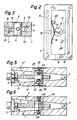
- the known leveling shoe shown in Figure 1 has a base plate 1, a top plate 2 and an intermediate wedge 3.
- Base and top plate 1 and 2 are provided with openings 4 and 5, with which the two plates 1 and 2 on a pin 6 vertically are guided.
- the head plate 2 is thus guided vertically relative to the foot plate 1 via this pin 6.
- the wedge 3 is penetrated by a screw spindle 7 when it projects through a through hole 8 and can be screwed into the threaded hole 9 of the pin 6. In this way, the wedge 3 is displaceable by the screw 7 relative to the two plates 1 and 2.
- the base plate 1, the top plate 2 and the wedge 3 are provided with guide grooves 10 which extend in the direction of the screw spindle 7 and in which guide strips 11 lie.
- the wedge 3 has contact surfaces 12 and 13 for surfaces 14 and 15 of the head plate 2 and the foot plate 1 which are intended to rest thereon.
- the guide strips 11 (insertion keys) allow the wedge to be displaced relative to the two plates 1 and 2 in the direction of the screw spindle 7 and represent a lateral guide, so that the three components 1, 2 and 3 are fixed in the horizontal, at right angles to the screw spindle 7.
- the lateral flanks of the guide strips 11 bear against the associated flanks of the respective channel 10.
- certain manufacturing tolerances must be allowed for the guidance of the guide strips 11 in the associated slide channel 10, so that a certain amount of play occurs.
- a spring element 16 designed as a leaf spring lies between the pin 6 and the wedge 3.
- the spring element 16 is therefore supported on one end on the pin 6 and on the other side on the wedge 3 and, in the illustration according to FIG. 2, presses the wedge 3 against the pin 6 to the left. Since the pin 6 is guided in the two openings 4 and 5 of the plates 1 and 2, the three components 1, 2 and 3 are thereby elastically clamped in the horizontal and at right angles to the screw spindle 7. As a result, the guide strips 11 are held with their flanks resiliently in positive engagement with the associated flanks of the channels 10.
- the bias of the spring element 16 can be changed in two ways.
- the support point of the spring element 16 on the pin 6 can be changed, wherein a screw 16 is adjustable in length in the pin 6.
- the pin-side support point of the spring element can thus be set at different distances from the pin 6, the wedge 3 being provided with a through hole 18 for access to the adjusting screw 17.
- a support point is adjusted.
- the bias of the spring element can also be achieved in that the spring element is arranged interchangeably, for installing another spring element with a different Fe dercharacteristics.
- FIG. 4 From Figure 4 it can be seen how the components of the leveling shoe are locked together vertically by tensioned spring elements.
- the same components are designated as in Figure 1.
- two spring elements 19 and 20 designed as leaf springs are provided, which are supported on one end on the pin 6 and on the other end on the foot or head plate 1 ⁇ , 2 ⁇ .
- the two plates 1 ⁇ and 2 ⁇ are provided with trough-shaped recesses 21 and 22 so that the spring elements 19, 20 with their fastening screws do not protrude beyond the base surface 23 of the base plate 1 ⁇ and the top surface 24 of the head plate 2 ⁇ .
- the components 1 ⁇ , 2 ⁇ and 3 are held in the vertical spring-elastic in their positive locking and thus blocked spring-elastic.
- the design according to FIG. 4 is expediently combined with the design according to FIG. 2, so that all components of the leveling shoe are locked together in the vertical and horizontal.
- FIG. 5 shows a further embodiment for blocking the components in the vertical.
- the spring elements 25 and 26 are designed as helical tension springs, which are supported on one end on the pin 6 ⁇ and the other end on insert plates 27 and 28 on the foot and head plate 1 ⁇ and 2 ⁇ .
- Countersunk screws 29, 30 sit in the plates 27, 28, and the turns of the springs 25, 26 can be screwed onto their passages. By screwing the screws 20, 30, the effective spring length of the springs 25, 26 is changed and thus the pretensioning of these spring elements 25, 26.
- the other ends of the springs 25, 26 are also located in threads that are located in the center of the pin 6 ⁇ .
- FIG. 7 indicates how a spring element acting in the vertical can be designed as a compression spring.
- the head plate 2 ′′′ is provided with a recess 32 in which a leaf spring 33 is located, which is engaged behind by the head 34 of a pin 6 ⁇ .
- the head 34 is in practice detachable from the pin 6 ⁇ .
- the interlocking of these components is maintained by the elastic locking of the individual components of the leveling shoe.
- the leveling shoe With an exciting frequency, the comparatively low natural frequency of the loosely lying components of the leveling shoe no longer has to be expected, but the leveling shoe, which is now in vibration as a block, has a different, higher natural frequency. This prevents undesired bouncing vibrations from occurring in the leveling shoe when passing through the natural frequency of the machine or the device standing on the leveling shoe.
- These avoided bouncing vibrations between the individual components of the leveling shoe previously had a deformation of the components, a constant enlargement of the Bearing play between the components and a change in the precise height alignment of the machine set by means of the leveling shoe.
- the now obtained other single frequency of the leveling shoe, which is present as a block, can still be changed by changing the preload of the spring elements.
- This variable prestressing of the spring elements will be carried out empirically, depending on the type of the machine lying on it and its working conditions.
- This adjustable prestressing of the spring elements can eliminate any manufacturing-related play between the components, which improves accuracy in the ⁇ m range. Such precision could only be achieved with extremely expensive, complex testicles in a different way.
- the leveling shoe, which is now available as a block in terms of vibrations also has, statically speaking, the advantage that it can be stored and transported as a block; ie the individual components of the leveling shoe are held together mechanically, so they can no longer fall apart.
Landscapes
- Engineering & Computer Science (AREA)
- General Engineering & Computer Science (AREA)
- Mechanical Engineering (AREA)
- Machine Tool Units (AREA)
- Clamps And Clips (AREA)
- Spinning Or Twisting Of Yarns (AREA)
- Wick-Type Burners And Burners With Porous Materials (AREA)
- Solid-Fuel Combustion (AREA)
- Footwear And Its Accessory, Manufacturing Method And Apparatuses (AREA)
- Sliding-Contact Bearings (AREA)
- Portable Nailing Machines And Staplers (AREA)
Abstract
Description
- Die Erfindung betrifft einen Nivellierschuh zur Höheneinstellung von Maschinen und Geräten, mit einer Fussplatte, einer vertikal dazu geführten Kopfplatte und zumindest einem dazwischenliegenden Keil, der durch eine ihn durchsetzende Schraubspindel gegenüber Fuss- und Kopfplatte verschiebbar ist, wobei die Schraubspindel in einem Zapfen verschraubbar ist, der axial vershiebbar in Kopf- und Fussplatte geführt ist, wobei der Keil sowie die Fuss- und Kopfplatte an ihren gegenseitigen Anlageflächen mit Führungsleisten versehen sind.
- Ein solcher Nivellierschuh ist zum Beispiel durch die DE-PS 1 297 409 bekannt. Dieser bewährte Nivellierschuh besteht aus mehreren Bauteilen, die formschlüssig aneinander anliegen. Dies betrifft die Auflageflächen zwischen Keil und Kopfplatte sowie zwischen Keil und Fussplatte, in Richtung der Schraubspindel, aber auch die Gleitflächen an den Führungsleisten. Letztere sind in entsprechenden Längsrinnen verschiebbar geführt und dienen zur seitlichen Fixierung von Kopf-, Fussplatte und Keil. Bei den vom Nivellierschuh getragenen Maschinen oder Geräten treten durch die Arbeitsdrehzahlen sowie durch andere rhythmische Schwungwechsel ein rasches Kräftespiel und damit verschiedene Schwingungsarten auf, die natürlich auch auf den Nivellierschuh übertragen werden. Um diese Schwingungen zu dämpfen, wurde bereits vorge schlagen die Bodenfläche der Fussplatte und die Deckfläche der Kopfplatte mit schwingungsdämpfenden Belägen zu versehen. Eine solche Massnahme kann natürlich nicht dann zufriedenstellend sein, wenn der Nivellierschuh nicht nur zur elastischen Lagerung dient, sondern zu einer präzisen Höheneinstellung der von ihm getragenen Maschine.
- Die Erfindung zeigt nunmehr einen Weg auf, um den gefährlichen Resonanzbereich unwirksam werden zu lassen. Dies wird nunmehr dadurch erreicht, dass die Eigenfrequenz des Nivellierschuhs verändert wird. Beim bekannten Nivellierschuh musste die Eigenfrequenz seiner Bauteile berücksichtigt werden, da die Bauteile lose aneinander anlagen, wobei herstellungsbedingte, zumutbare Toleranzen an den Gleitflächen vorhanden sind, die diese Eigenfrequenz der einzelnen Bauteile ermöglichen. Beim Hochfahren der vom Nivellierschuh getragenen Maschine kommt man nunmehr durch den Eigenfrequenzbereich der verschiedenen Bauteile des Nivellierschuhs, so dass immer wieder einzelne Partien des Nivelliershcuhs zur Resonanz kommen. Es ist klar verständlich, dass dies sowohl für die Gleit-und Führungsflächen der einzelnen Bauteile sowei auch für das präzise Höhenmass des gesamten Nivellierschuhs nur von Nachteil ist. Es wird die Schaffung eines Nivellierschuhs eingangs genannter Art bezweckt, mit dem dieser Nachteil vermieden werden kann.
- Der erfindungsgemässe Nivellierschuh ist gekennzeichnet durch zwischen den Schuhbauteilen angeordnete, gespannte Federelemente zur federelastischen Aufrechterhaltung ihres Formschlusses.
- Im folgenden werden der bekannte Nivellierschuh eingangs genannter Art sowie mehrere Ausführungsbeispiele des erfindungsgemässen Nivellierschuhs anhand von Zeichnungen erläutert. Es zeigen:
- Figur 1 der bekannte Nivellierschuh eingangs genannter Art, in einer schaubildlichen Explosionsdarstellung, wobei dieser Nivellierschuh erfindungsgemäss ausge staltet werden kann,
- Figur 2 einen Teil des Nivellierschuhs nach Figur 1 mit der erfindungsgemässen Massnahme, in Draufsicht,
- Figur 3 einen Vertikalschnitt durch den Bauteil nach Figur 2,
- Figur 4 einen Längs-Vertikalschnitt durch den Nivellierschuh nach Figur 1, mit der erfindungsgemässen Massnahme
- Figur 5 eine gleiche Schnittdarstellung wie in Figur 4, bei einer anderen Ausführungsform des erfindungsgemässen Nivellierschuhs,
- Figur 6 eine gleiche Darstellung wie in den Figuren 4 und 5, bei einer weiteren Ausführungsform des erfin dungsgemässen Nivellierschuhs, und
- Figur 7 einen Ausschnitt aus einer gleichen Darstellung wie in den Figuren 4-6, bei einer weiteren Ausführungsform des erfindungsgemässen Nivellierschuhs.
- Der in Figur 1 gezeigte bekannte Nivellierschuh hat eine Fussplatte 1, eine Kopfplatte 2 und einen dazwischenliegenden Keil 3. Fuss- und Kopfplatte 1 bzw. 2 sind mit Durchbrechungen 4 und 5 versehen, mit denen die beiden Platten 1 und 2 auf einem Zapfen 6 vertikal verschiebbar geführt sind. Ueber diesen Zapfen 6 ist also die Kopfplatte 2 gegenüber der Fussplatte 1 vertikal geführt. Der Keil 3 wird von einer Schraubspindel 7 durchsetzt, wenn diese durch ein Durchgangsloch 8 hindurchragt und im Gewindeloch 9 des Zapfens 6 verschraubbar ist. Auf diese Weise ist der Keil 3 durch die Schraubspindel 7 gegenüber den beiden Platten 1 und 2 verschiebbar. Die Fussplatte 1, die Kopfplatte 2 und der Keil 3 sind mit sich in Richtung der Schraubspindel 7 erstreckenden Führungsrinnen 10 versehen, in denen Führungsleisten 11 liegen. Der Keil 3 hat Anlageflächen 12 und 13 für daran zum Anliegen bestimmte Flächen 14 und 15 der Kopfplatte 2 und der Fussplatte 1. Die Führungsleisten 11 (Einlege-Passfedern) erlauben ein Verschieben des Keiles gegenüber den beiden Platten 1 und 2 in Richtung der Schraubspindel 7 und stellen eine seitliche Führung dar, so dass die drei Bauteile 1,2 und 3 in der Horizontalen, rechtwinklig zur Schraubspindel 7, festgelegt sind. Hierbei liegen die seitlichen Flanken der Führungsleisten 11 an den zugeordneten Flanken der jeweiligen Rinne 10 an. Aus wirtschaftlichen Gründen müssen für die Führung der Führungsleisten 11 in der zugeordneten Gleitrinne 10 gewisse Fertigungstoleranzen zugestanden werden, so dass also ein gewisses Speil auftritt.
- Zur erfindungsgemässen Ausbildung des Nivellierschuhs sind nunmehr gespannte Federelemente vorhanden. Beim Ausführungsbeispiel nach Figur 2 liegt ein als Blattfeder ausgebildetes Federelement 16 zwischen dem Zapfen 6 und dem Keil 3. Das Federelement 16 is also einerends am Zapfen 6 und andererends am Keil 3 abgestützt und drückt in der Darstellung nach Figur 2 den Keil 3 gegenüber dem Zapfen 6 nach links. Da der Zapfen 6 in den beiden Durchbrechungen 4 und 5 der Platten 1 und 2 geführt ist, werden hierdurch die drei Bauteile 1, 2 und 3 in der Horizontalen und rechtwinklig zur Schraubspindel 7 federelastisch verspannt. Hierdurch werden die Führungsleisten 11 mit ihren Flanken federelastisch in Formschluss mit den zugeordneten Flanken der Rinnen 10 gehalten. Die Vorspannung des Federelementes 16 kann auf zweierlei Art geändert werden. Im dargestellten Fall nach Figur 2 kann die Abstützstelle des Federelementes 16 am Zapfen 6 verändert werden, wobei eine Schraube 16 längenverstellbar im Zapfen 6 sitzt. Die zapfenseitige Abstützstelle des Federelementes kann somit in verschiedene Abstände zum Zapfen 6 eingestellt werden, wobei für den Zugang zur Verstellschraube 17 der Keil 3 mit einer Durchgangsbohrung 18 versehen ist. Bei dieser Art der Veränderung der Vorspannung des Federelementes 16 wird also eine Abstützstelle verstellt. Die Vorspannung des Federelementes kann aber auch dadurch erreicht werden, dass das Federelement auswechselbar angeordnet ist, zum Einbau eines anderen Federelementes mit einer anderen Fe dercharakteristik.
- Aus Figur 4 ist ersichtlich, wie die Bauteile des Nivellierschuhs in der Vertikalen durch gespannte Federelemente miteinander verblockt werden. Gleiche Bauteile sind wie in Figur 1 bezeichnet. Beim Beispiel nach Figur 4 sind zwei als Blattfedern ausgebildete Federelemente 19 und 20 vorhanden, die einerends am Zapfen 6 und andererends an der Fuss- bzw. Kopfplatte 1ʹ, 2ʹ abgestützt sind. Die beiden Platten 1ʹ und 2ʹ sind hierbei mit wannenförmigen Ausnehmungen 21 und 22 versehen, damit die Federelemente 19,20 mit ihren Befestigungsschrauben nicht über die Basisfläche 23 der Fussplatte 1ʹ und der Deckfläche 24 der Kopfplatte 2ʹ hervorragen. Durch diese Federelem ente 19 und 20 werden die Bauteile 1ʹ, 2ʹ und 3 in der Vertikalen federelastisch in ihrem Formschluss gehalten und somit federelastisch verblockt. Die Ausbildung nach Figur 4 wird in zweckmässiger Weise mit der Ausbildung nach Figur 2 kombiniert, so dass also alle Bauteile des Nivellierschuhs in der Vertikalen und der Horizontalen miteinander verblockt sind.
- In Figur 5 ist eine weitere Ausführungsform für ein Verblocken der Bauteile in der Vertikalen gezeigt. Die Federelemente 25 und 26 sind hierbei als Schraubenzugfedern ausgebildet, die einerends am Zapfen 6ʹ und andererends über Einlegeplatten 27 bzw. 28 and der Fuss- und Kopfplatte 1ʺ bzw. 2ʺ abgestützt sind. In den Platten 27,28 sitzen Senkschrauben 29,30, auf deren Gänge die Windungen der Federn 25,26 verschraubbar sind. Durch Verschrauben der Schrauben 20,30 wird die wirksame Federlänge der Feden 25,26 verändert und somit die Vorspannung dieser Federelemente 25,26. Die anderen Enden der Federn 25, 26 sitzen ebenfalls in Gewindegängen, die sich im Zentrum des Zapfens 6ʹ befinden.
- Beim Beispiel nach Figur 6 ist nur ein Federelement in der Form einer Schraubenzugfeder 31 vorhanden, die einerends an der Fussplatte 1 und andererends an der Kopf platte 2 abgestützt ist. Hierzu dienen wiederum die zwei Senkschrauben 29 und 30. Durch Verschrauben der Federwindungen in den Gewindegängen der Schrauben 29 und 30 wird wiederum die wirksame Federlänge der Feder 31 verändert. Die Feder 31 liegt aber, im Gegensatz zu den Federn 25 und 26 vom Beispiel nach Figur 5, nicht mehr im Zentrum des Zapfens 6 sondern ausserhalb, wie es in Figur 2 angedeutet ist. Bei einem anderen, nicht im Vertikalschnitt gezeigten Ausführungsbeispiel könnte ein solches Federelement 31 auch in zweifacher Weise und in anderer Lage vorgesehen werden, so wie es mittels der Senkrschraube 29ʹ in Figur 2 gezeigt ist. Vor allem wenn der Nivellierschuh eine grosse und damit auch lange Ausbildung hat, empfehlen sich mehrere Federelemente in der Vertikalen. Bei den bisher erläuterten Ausführungsbeispielen waren die Federelemente als Zugfedern ausgebildet. In Figur 7 ist angedeutet, wie ein in der Vertikalen wirkendes Federelement als Druckfeder ausgebildet sein kann. Die Kopfplatte 2‴ ist mit einer Ausnehmung 32 versehen, in der eine Blattfeder 33 liegt, die vom Kopf 34 eines Zapfens 6ʺ hintergriffen wird. Aus Montagegründen wird in der Praxis der Kopf 34 lösbar vom Zapfen 6ʺ ausgebildet.
- Durch das federelastische Verblocken der einzelnen Bauteile des Nivellierschuhs wird der Formschluss dieser Bauteile federelastisch aufrecht erhalten. Bei einer erregenden Frequenz muss nun nicht mehr mit der verhältnismässig niedrigen Eigenfrequenz der lose aneinanderliegenden Bauteile des Nivellierschuhs gerechnet werden, sondern der nunmehr schwingungsmässig als Block vorliegende Nivellierschuh hat eine andere, höhere Eigenfrequenz. Hierdurch wird vermieden, dass beim Durchfahren der Eigenfrequenz der Maschine oder des Gerätes, das auf dem Nivellierschuh steht, unerwünschte Prellschwingungen im Nivellierschuh entstehen. Diese vermiedenen Prellschwingungen zwischen den einzelnen Bauteilen des Nivellierschuhs hatten bisher ein Verformen der Bauteile, ein ständiges Vergrössern des Lagerspiels zwischen den Bauteilen und eine Veränderung der mittels des Nivellierschuhs eingestellten präzisen Höhenausrichtung der Maschine zur Folge. Die nunmehr erhaltene andere Eingenfrequenz des als ein Block vorliegenden Nivellierschuhs kann noch durch Verändern der Vorspannung der Federelemente geändert werden. Diese veränderliche Vorspannung der Federelemente wird man empirisch vornehmen, je nach Art der aufliegenden Maschine und ihrer Arbeitsbedingungen. Durch diese regulierbare Vorspannung der Federelemente kann jegliches herstellungsbedingtes Spiel zwischen den Bauteilen aufgehoben werden, wodurch eine Genauigkeit im µm-Bereich verbessert wird. Eine solche Präzision könnte auf andere Art nur mirt extrem teuren, aufwendigen Bearbeitungs hoden erreicht werden. Der schwingungsmässig nunmehr als ein Block vorliegende Nivellierschuh hat auch noch, statisch gesehen, den Vorteil, dass er als ein Block lagerbar und transportierbar ist; d.h. die einzelnen Bauteile des Nivellierschuhs werden mechanisch zusammengehalten, können also nicht mehr auseinanderfallen. Ein solches Auseinanderfallen der einzelnen Bauteile beim Transport, bei der Lagerung und bei der Vormontage hatte ja einen verhältnismässig grossen Mehraufwand zur Wiedermontage zur Folge mit der Gefahr einer Fehlmontage und hierdurch entstehende Funktionsmängel. Durch die erwähnte nunmehr hohe Eigenfrequenz des shwingungsmässig als ein Block vorliegenden Nivellierschuhs wird auch der grosse Vorteil erzielt, dass diese Art des Nivellierschuhs bei Stockwerkaufstellungen von Maschinen und Geräten sehr vorteilhaft ist, da die Eigenfrequenz des Nivellierschuhs höher als die Deckenfrequenz eingestellt werden kann, so dass Resonanz vermieden wird.
Claims (8)
Priority Applications (1)
| Application Number | Priority Date | Filing Date | Title |
|---|---|---|---|
| AT87101282T ATE71447T1 (de) | 1986-10-24 | 1987-01-30 | Nivellierschuh. |
Applications Claiming Priority (2)
| Application Number | Priority Date | Filing Date | Title |
|---|---|---|---|
| CH4237/86 | 1986-10-24 | ||
| CH4237/86A CH672009A5 (de) | 1986-10-24 | 1986-10-24 |
Publications (2)
| Publication Number | Publication Date |
|---|---|
| EP0264520A1 true EP0264520A1 (de) | 1988-04-27 |
| EP0264520B1 EP0264520B1 (de) | 1992-01-08 |
Family
ID=4272364
Family Applications (1)
| Application Number | Title | Priority Date | Filing Date |
|---|---|---|---|
| EP87101282A Expired - Lifetime EP0264520B1 (de) | 1986-10-24 | 1987-01-30 | Nivellierschuh |
Country Status (8)
| Country | Link |
|---|---|
| US (1) | US4858865A (de) |
| EP (1) | EP0264520B1 (de) |
| JP (1) | JPH0654126B2 (de) |
| KR (1) | KR950001464B1 (de) |
| AT (1) | ATE71447T1 (de) |
| CH (1) | CH672009A5 (de) |
| DE (1) | DE3775877D1 (de) |
| ES (1) | ES2029800T3 (de) |
Cited By (11)
| Publication number | Priority date | Publication date | Assignee | Title |
|---|---|---|---|---|
| DE102007011197B3 (de) * | 2007-03-06 | 2008-06-12 | Cvt Industriebedarf Gmbh | Nivellierschuh |
| DE102008012787A1 (de) | 2007-03-06 | 2008-09-11 | Cvt Industriebedarf Gmbh | Nivellierschuh |
| CN100439787C (zh) * | 2005-01-18 | 2008-12-03 | 哈尔滨工业大学 | 带有万向均载机构的调整垫铁 |
| DE102007025382A1 (de) | 2007-05-30 | 2008-12-11 | Effbe Gmbh | Nivellierschuh |
| WO2010132102A1 (en) * | 2009-05-14 | 2010-11-18 | Softway Industrial Solutions, Llc | Shimless aligner |
| DE102011106679B3 (de) * | 2011-07-05 | 2012-07-26 | Süleyman Güney | Nivellierschuh und Verfahren zum Montieren eines Nivellierschuhs |
| CN103307062A (zh) * | 2013-06-06 | 2013-09-18 | 四川航天系统工程研究所 | 一种通用快锁接头 |
| CN106050825A (zh) * | 2016-06-16 | 2016-10-26 | 哈尔滨理工大学 | 有效载荷快速连接支座 |
| CN108612715A (zh) * | 2018-04-27 | 2018-10-02 | 合肥托卡拉图科技有限公司 | 一种自限位式快速装夹螺栓及其安装方法 |
| CN115506500A (zh) * | 2021-06-23 | 2022-12-23 | 昆明理工大学 | 一种新型变摩擦阻尼器 |
| WO2024200324A1 (en) * | 2023-03-24 | 2024-10-03 | Autostore Technology AS | Leveling device |
Families Citing this family (55)
| Publication number | Priority date | Publication date | Assignee | Title |
|---|---|---|---|---|
| US5110082A (en) * | 1988-09-21 | 1992-05-05 | Rowan Jr Robert L | Adjustable apparatus for supporting machinery or other load |
| US5095767A (en) * | 1990-08-23 | 1992-03-17 | Geartechnic Corporation | Multi-configuration gear reducer kit |
| US5492292A (en) * | 1993-05-05 | 1996-02-20 | Richards; Jeffrey | Device for supporting and stabilizing furniture |
| US5482236A (en) * | 1993-12-23 | 1996-01-09 | Storage Technology Corporation | Locking leveler |
| DE4429813C2 (de) * | 1994-08-23 | 1998-02-19 | Isoloc Schwingungstechnik Gmbh | Nivellierschuh |
| EP0826127B1 (de) * | 1995-05-23 | 2002-03-20 | J.P. Bell & Co. | Nivelliergerät für maschine |
| US5878983A (en) * | 1995-10-10 | 1999-03-09 | Illinois Tool Works Inc. | Load leveling assembly |
| CA2200414C (en) * | 1997-03-19 | 2007-02-13 | Dale Robert Marshall | Adjustable cantilever foot assembly for furniture |
| US5878985A (en) * | 1997-03-21 | 1999-03-09 | Iannone; James R. | Shim for window treatment bracket |
| DE19824378A1 (de) * | 1998-05-30 | 1999-12-02 | Philips Patentverwaltung | Elektonisches Gerät mit einer erschütterungsempfindliches Baueinheit |
| USH2009H1 (en) * | 1998-08-07 | 2002-01-01 | The United States Of America As Represented By The Secretary Of The Navy | Height adjustment device for load support |
| US6889946B2 (en) * | 1999-12-11 | 2005-05-10 | Nivell Ag | Leveling shoe |
| JP2002148219A (ja) * | 2000-11-08 | 2002-05-22 | Mac Science Co Ltd | X線回折装置 |
| US6663061B1 (en) * | 2002-10-02 | 2003-12-16 | William O. Morris | Vehicle seat leveling system |
| JP4160824B2 (ja) * | 2002-12-20 | 2008-10-08 | 日本トムソン株式会社 | 昇降用案内ユニット及びそれを組み込んだステージ装置 |
| US7343712B2 (en) * | 2003-09-25 | 2008-03-18 | Shelton David R | Wooden member support retrofit system and method |
| WO2005068749A1 (en) * | 2004-01-13 | 2005-07-28 | Itools Aps | A distance piece |
| US7331146B1 (en) * | 2004-06-29 | 2008-02-19 | B3 Products, Inc. | Window and door jamb adjustment system |
| US7703727B2 (en) * | 2004-07-21 | 2010-04-27 | Selness Jerry N | Universal adjustable spacer assembly |
| US7717395B2 (en) * | 2004-09-16 | 2010-05-18 | Robert L. Rowan & Associates, Inc. | Adjustable support apparatus for machinery |
| DE102004052216B4 (de) * | 2004-10-18 | 2006-08-10 | Joma-Polytec Kunststofftechnik Gmbh | Einrichtung zur Anordung zwischen einen Rahmen eines Fensters oder einer Türe und einer dem Rahmen zugeordneten Leibung |
| DE202005012626U1 (de) * | 2005-05-19 | 2006-09-28 | Liebherr-Hausgeräte Ochsenhausen GmbH | Stellfußeinheit eines Haushaltsgerätes |
| US7328879B1 (en) * | 2005-06-03 | 2008-02-12 | The United States Of America As Represented By The Secretary Of The Navy | Equipment installation support on foundation |
| DE102007004410A1 (de) | 2007-01-30 | 2008-09-25 | Cae Consulting & Engineering Gmbh | Einstellbare Stützvorrichtung auf Basis eines oder mehreren verformbaren Schalenelementen |
| DE102007006087A1 (de) | 2007-02-07 | 2008-08-14 | Cae Consulting & Engineering Gmbh | Einstellbare Stützvorrichtung auf Basis der Elemente Innendoppelkeil, Außendoppelkeil wahlweise Rollensystem und Stellschraube mit Links- und Rechtsgewinde |
| JP5013195B2 (ja) * | 2007-10-24 | 2012-08-29 | 倉敷化工株式会社 | 高さ調整機構及びそれを備えたレベリング装置 |
| US8819743B2 (en) * | 2007-12-19 | 2014-08-26 | Dish Network L.L.C. | Transfer of data related to broadcast programming over a communication network |
| US8907862B2 (en) | 2011-04-12 | 2014-12-09 | Dish Network L.L.C. | Apparatus and systems for mounting an electrical switching device |
| US9337545B2 (en) | 2008-06-20 | 2016-05-10 | Dish Network L.L.C. | Apparatus and systems for mounting an electrical switching device |
| CN101945547B (zh) * | 2009-07-09 | 2014-12-10 | 鸿富锦精密工业(深圳)有限公司 | 电子装置 |
| US8462075B2 (en) * | 2010-02-23 | 2013-06-11 | Dish Network L.L.C. | Apparatus for mounting an object to a railing |
| IT1402245B1 (it) * | 2010-09-24 | 2013-08-28 | Sinetica Ind S R L | Giunto di collegamento per elementi tubolari di una struttura componibile e relativo procedimento di montaggio. |
| CN102062278A (zh) * | 2010-11-25 | 2011-05-18 | 谢寄彪 | 一种机械设备精密万向调整垫铁 |
| JP4914934B1 (ja) * | 2010-11-26 | 2012-04-11 | 株式会社ナベヤ | レベリング装置 |
| US8646186B2 (en) | 2010-12-16 | 2014-02-11 | Dish Network L.L.C. | Multi-angle levels and plumbing methods |
| US20120175475A1 (en) * | 2011-01-12 | 2012-07-12 | Mcerlane Scott | Rotatable table leveling disk |
| USD679574S1 (en) * | 2011-02-24 | 2013-04-09 | Azek Building Products, Inc. | Angle shim |
| CN102233369A (zh) * | 2011-04-13 | 2011-11-09 | 无锡市桥联冶金机械有限公司 | 斜楔对中装置 |
| TWI409399B (zh) * | 2011-04-29 | 2013-09-21 | 力鼎精密股份有限公司 | 小型化支撐微調裝置 |
| US8272805B1 (en) * | 2011-05-06 | 2012-09-25 | Dinnison Jay G | Portable wedge clamp device |
| US8802985B2 (en) | 2011-09-07 | 2014-08-12 | Dish Network L.L.C. | In-wall extension apparatus |
| CN103144330A (zh) * | 2011-12-07 | 2013-06-12 | 软控股份有限公司 | 轮胎三鼓成型机及其物料输送方法 |
| DE202011052458U1 (de) * | 2011-12-23 | 2013-03-25 | Gea Mechanical Equipment Gmbh | Zentrifugenanordnung |
| JP5559215B2 (ja) * | 2012-01-20 | 2014-07-23 | 株式会社ナベヤ | レベリング装置 |
| AU2013202333B2 (en) * | 2012-04-04 | 2015-05-14 | Elmich Pte Ltd | Chock for paver support |
| US9123987B2 (en) | 2012-07-31 | 2015-09-01 | Dish Network L.L.C. | Antenna mounting systems and methods |
| US20140216098A1 (en) * | 2013-02-04 | 2014-08-07 | Metro Industries Inc. | Mobile refrigeration cabinet |
| US9303532B2 (en) * | 2013-04-18 | 2016-04-05 | General Electric Company | Adjustable gib shim |
| CN107207229B (zh) * | 2014-12-10 | 2019-04-30 | 意科微米股份有限公司 | 设备校平器 |
| CN104772261B (zh) * | 2015-04-27 | 2017-06-30 | 合肥京东方光电科技有限公司 | 一种涂布机及其控制方法 |
| PL417068A1 (pl) * | 2016-05-02 | 2017-11-06 | Włodzimierz Grobelny | Przyrząd do montażu okien |
| AT520435B1 (de) | 2017-11-08 | 2019-04-15 | Janda Alexander | Spann- oder Hebewerkzeug |
| JP6795564B2 (ja) * | 2018-10-10 | 2020-12-02 | ファナック株式会社 | 支持構造および工作機械システム |
| DE102018218110A1 (de) * | 2018-10-23 | 2020-04-23 | Carl Zeiss Smt Gmbh | Abstandshalter, optisches system und lithographieanlage |
| US20240026725A1 (en) * | 2022-07-19 | 2024-01-25 | Michael David Strickland | System for Hollow Metal Frame Installation |
Citations (4)
| Publication number | Priority date | Publication date | Assignee | Title |
|---|---|---|---|---|
| FR664570A (fr) * | 1928-03-03 | 1929-09-05 | Cale extensible | |
| FR36725E (fr) * | 1929-02-04 | 1930-08-02 | Cale extensible | |
| DE1297409B (de) * | 1966-01-14 | 1969-06-12 | Schrepfer Rudolf | Nivellierschuh |
| DE2448451A1 (de) * | 1974-10-10 | 1976-04-22 | Mgs Maschinenueberholungen Ger | Einstellbares auflager, insbesondere fuer maschinenuntergestelle von werkzeugmaschinen |
Family Cites Families (5)
| Publication number | Priority date | Publication date | Assignee | Title |
|---|---|---|---|---|
| US3495896A (en) * | 1967-10-18 | 1970-02-17 | Gen Motors Corp | Push-pull nonglare mirror |
| FR1550287A (de) * | 1967-10-31 | 1968-12-20 | ||
| DE2620162C3 (de) * | 1976-05-07 | 1982-02-04 | Effbe-Werk Fritz Brumme Gmbh & Co Kg, 6096 Raunheim | Höhenverstellbare, schwingungsisolierende Abstützvorrichtung für Maschinen u.dgl. |
| DE3012986A1 (de) * | 1980-04-03 | 1981-10-08 | M.A.N.- Roland Druckmaschinen AG, 6050 Offenbach | Hilfseinrichtung fuer die aufstellung von schwerlasten an einer stellflaeche |
| US4436268A (en) * | 1981-07-20 | 1984-03-13 | Schriever Frederick G | Self-aligning load leveling device |
-
1986
- 1986-10-24 CH CH4237/86A patent/CH672009A5/de not_active IP Right Cessation
-
1987
- 1987-01-30 ES ES198787101282T patent/ES2029800T3/es not_active Expired - Lifetime
- 1987-01-30 DE DE8787101282T patent/DE3775877D1/de not_active Expired - Fee Related
- 1987-01-30 EP EP87101282A patent/EP0264520B1/de not_active Expired - Lifetime
- 1987-01-30 AT AT87101282T patent/ATE71447T1/de not_active IP Right Cessation
- 1987-02-19 JP JP62036849A patent/JPH0654126B2/ja not_active Expired - Fee Related
- 1987-05-15 KR KR1019870004785A patent/KR950001464B1/ko not_active Expired - Fee Related
- 1987-10-20 US US07/110,337 patent/US4858865A/en not_active Expired - Lifetime
Patent Citations (4)
| Publication number | Priority date | Publication date | Assignee | Title |
|---|---|---|---|---|
| FR664570A (fr) * | 1928-03-03 | 1929-09-05 | Cale extensible | |
| FR36725E (fr) * | 1929-02-04 | 1930-08-02 | Cale extensible | |
| DE1297409B (de) * | 1966-01-14 | 1969-06-12 | Schrepfer Rudolf | Nivellierschuh |
| DE2448451A1 (de) * | 1974-10-10 | 1976-04-22 | Mgs Maschinenueberholungen Ger | Einstellbares auflager, insbesondere fuer maschinenuntergestelle von werkzeugmaschinen |
Cited By (14)
| Publication number | Priority date | Publication date | Assignee | Title |
|---|---|---|---|---|
| CN100439787C (zh) * | 2005-01-18 | 2008-12-03 | 哈尔滨工业大学 | 带有万向均载机构的调整垫铁 |
| DE102008012787B4 (de) * | 2007-03-06 | 2009-11-05 | Cvt Industriebedarf Gmbh | Nivellierschuh |
| DE102008012787A1 (de) | 2007-03-06 | 2008-09-11 | Cvt Industriebedarf Gmbh | Nivellierschuh |
| DE102007011197B3 (de) * | 2007-03-06 | 2008-06-12 | Cvt Industriebedarf Gmbh | Nivellierschuh |
| DE102007025382B4 (de) * | 2007-05-30 | 2011-09-22 | Effbe Gmbh | Nivellierschuh |
| DE102007025382A1 (de) | 2007-05-30 | 2008-12-11 | Effbe Gmbh | Nivellierschuh |
| WO2010132102A1 (en) * | 2009-05-14 | 2010-11-18 | Softway Industrial Solutions, Llc | Shimless aligner |
| DE102011106679B3 (de) * | 2011-07-05 | 2012-07-26 | Süleyman Güney | Nivellierschuh und Verfahren zum Montieren eines Nivellierschuhs |
| CN103307062A (zh) * | 2013-06-06 | 2013-09-18 | 四川航天系统工程研究所 | 一种通用快锁接头 |
| CN106050825A (zh) * | 2016-06-16 | 2016-10-26 | 哈尔滨理工大学 | 有效载荷快速连接支座 |
| CN106050825B (zh) * | 2016-06-16 | 2018-01-19 | 哈尔滨理工大学 | 有效载荷快速连接支座 |
| CN108612715A (zh) * | 2018-04-27 | 2018-10-02 | 合肥托卡拉图科技有限公司 | 一种自限位式快速装夹螺栓及其安装方法 |
| CN115506500A (zh) * | 2021-06-23 | 2022-12-23 | 昆明理工大学 | 一种新型变摩擦阻尼器 |
| WO2024200324A1 (en) * | 2023-03-24 | 2024-10-03 | Autostore Technology AS | Leveling device |
Also Published As
| Publication number | Publication date |
|---|---|
| EP0264520B1 (de) | 1992-01-08 |
| JPH0654126B2 (ja) | 1994-07-20 |
| ES2029800T3 (es) | 1992-10-01 |
| ATE71447T1 (de) | 1992-01-15 |
| US4858865A (en) | 1989-08-22 |
| DE3775877D1 (de) | 1992-02-20 |
| JPS63111304A (ja) | 1988-05-16 |
| KR880005380A (ko) | 1988-06-29 |
| KR950001464B1 (ko) | 1995-02-24 |
| CH672009A5 (de) | 1989-10-13 |
Similar Documents
| Publication | Publication Date | Title |
|---|---|---|
| EP0264520B1 (de) | Nivellierschuh | |
| DE60200450T2 (de) | Werkzeugträger | |
| EP2726237B1 (de) | Anordnung mindestens eines nutensteins und eines werkzeughalters für werkzeuge und anordnung mindestens eines nutensteins und eines werkzeugträgers zur aufnahme eines werkzeughalters | |
| DD285562A5 (de) | Einstellvorrichtung, insbesondere fuer werkzeuge | |
| EP0142069A2 (de) | Vorspannelement für Umlaufschuhe und entsprechend wirkende Linearlager | |
| DE4007937A1 (de) | Elastisch gelagerte schiene fuer schienenfahrzeuge | |
| EP0275923A2 (de) | Aufspannvorrichtung für Werkstücke | |
| EP1468480B1 (de) | Dynamoelektrische maschine mit verkeilten wicklungsstäben | |
| DE4432607A1 (de) | Kraftmeßvorrichtung | |
| EP0968783A1 (de) | Kurzklemmhalter mit radialer Feinverstellung | |
| EP0739680B1 (de) | Vorrichtung zum Einrichten eines Oberteils relativ zu einem Unterteil | |
| EP0154813A1 (de) | Spannvorrichtung für Werkzeugmaschinen | |
| EP0838144A1 (de) | Gerät zum Schneiden von Pflanzen | |
| DE10157676A1 (de) | Einrichtung zum seitlichen Abstützen einer Schiene | |
| EP0497322A1 (de) | Blattfederanordnung für den Schwingkopf einer Vibrations-Schweissmaschine | |
| CH692010A5 (de) | Vorrichtung zum Aufspannen und Ausrichten eines Werkzeugs oder Werkstücks. | |
| DE3611672C2 (de) | ||
| EP0455973A1 (de) | Führungsleiste für Aufzugstür | |
| DE2940398A1 (de) | Handhobelmaschine | |
| EP0154032B1 (de) | Schwingförderer mit einer gestreckten Förderrinne | |
| DE4318025A1 (de) | Lagerstanze für die Unterzylinder von Streckwerken bei Spinnereimaschinen | |
| DE3329151A1 (de) | Laengsfuehrung | |
| DE3812815A1 (de) | Schaftbacke, insbesondere fuer sportgewehre | |
| DE953890C (de) | Schwingankermotor, dessen Anker auf zwei entgegengesetzten Seiten Laengskugellager zur Parallelfuehrung besitzt | |
| DE622290C (de) | Formvorrichtung |
Legal Events
| Date | Code | Title | Description |
|---|---|---|---|
| PUAI | Public reference made under article 153(3) epc to a published international application that has entered the european phase |
Free format text: ORIGINAL CODE: 0009012 |
|
| AK | Designated contracting states |
Kind code of ref document: A1 Designated state(s): AT DE ES FR GB IT SE |
|
| 17P | Request for examination filed |
Effective date: 19880630 |
|
| 17Q | First examination report despatched |
Effective date: 19890516 |
|
| GRAA | (expected) grant |
Free format text: ORIGINAL CODE: 0009210 |
|
| RAP1 | Party data changed (applicant data changed or rights of an application transferred) |
Owner name: AIR-LOC SCHREPFER AG |
|
| ITF | It: translation for a ep patent filed | ||
| AK | Designated contracting states |
Kind code of ref document: B1 Designated state(s): AT DE ES FR GB IT SE |
|
| REF | Corresponds to: |
Ref document number: 71447 Country of ref document: AT Date of ref document: 19920115 Kind code of ref document: T |
|
| REF | Corresponds to: |
Ref document number: 3775877 Country of ref document: DE Date of ref document: 19920220 |
|
| GBT | Gb: translation of ep patent filed (gb section 77(6)(a)/1977) | ||
| ET | Fr: translation filed | ||
| REG | Reference to a national code |
Ref country code: ES Ref legal event code: FG2A Ref document number: 2029800 Country of ref document: ES Kind code of ref document: T3 |
|
| PLBE | No opposition filed within time limit |
Free format text: ORIGINAL CODE: 0009261 |
|
| STAA | Information on the status of an ep patent application or granted ep patent |
Free format text: STATUS: NO OPPOSITION FILED WITHIN TIME LIMIT |
|
| 26N | No opposition filed | ||
| EAL | Se: european patent in force in sweden |
Ref document number: 87101282.9 |
|
| PGFP | Annual fee paid to national office [announced via postgrant information from national office to epo] |
Ref country code: ES Payment date: 19970731 Year of fee payment: 11 |
|
| PG25 | Lapsed in a contracting state [announced via postgrant information from national office to epo] |
Ref country code: ES Free format text: LAPSE BECAUSE OF NON-PAYMENT OF DUE FEES Effective date: 19980131 |
|
| PGFP | Annual fee paid to national office [announced via postgrant information from national office to epo] |
Ref country code: SE Payment date: 20011121 Year of fee payment: 16 |
|
| PGFP | Annual fee paid to national office [announced via postgrant information from national office to epo] |
Ref country code: DE Payment date: 20011123 Year of fee payment: 16 |
|
| PGFP | Annual fee paid to national office [announced via postgrant information from national office to epo] |
Ref country code: AT Payment date: 20011214 Year of fee payment: 16 |
|
| PGFP | Annual fee paid to national office [announced via postgrant information from national office to epo] |
Ref country code: FR Payment date: 20011221 Year of fee payment: 16 |
|
| REG | Reference to a national code |
Ref country code: GB Ref legal event code: IF02 |
|
| PGFP | Annual fee paid to national office [announced via postgrant information from national office to epo] |
Ref country code: GB Payment date: 20020116 Year of fee payment: 16 |
|
| PG25 | Lapsed in a contracting state [announced via postgrant information from national office to epo] |
Ref country code: GB Free format text: LAPSE BECAUSE OF NON-PAYMENT OF DUE FEES Effective date: 20030130 Ref country code: AT Free format text: LAPSE BECAUSE OF NON-PAYMENT OF DUE FEES Effective date: 20030130 |
|
| PG25 | Lapsed in a contracting state [announced via postgrant information from national office to epo] |
Ref country code: SE Free format text: LAPSE BECAUSE OF NON-PAYMENT OF DUE FEES Effective date: 20030131 |
|
| PG25 | Lapsed in a contracting state [announced via postgrant information from national office to epo] |
Ref country code: DE Free format text: LAPSE BECAUSE OF NON-PAYMENT OF DUE FEES Effective date: 20030801 |
|
| EUG | Se: european patent has lapsed | ||
| GBPC | Gb: european patent ceased through non-payment of renewal fee | ||
| PG25 | Lapsed in a contracting state [announced via postgrant information from national office to epo] |
Ref country code: FR Free format text: LAPSE BECAUSE OF NON-PAYMENT OF DUE FEES Effective date: 20030930 |
|
| REG | Reference to a national code |
Ref country code: FR Ref legal event code: ST |
|
| PG25 | Lapsed in a contracting state [announced via postgrant information from national office to epo] |
Ref country code: IT Free format text: LAPSE BECAUSE OF NON-PAYMENT OF DUE FEES;WARNING: LAPSES OF ITALIAN PATENTS WITH EFFECTIVE DATE BEFORE 2007 MAY HAVE OCCURRED AT ANY TIME BEFORE 2007. THE CORRECT EFFECTIVE DATE MAY BE DIFFERENT FROM THE ONE RECORDED. Effective date: 20050130 |