EP0266332A1 - Mechanische Vorrichtung zum Stabilisieren einer Plattform - Google Patents
Mechanische Vorrichtung zum Stabilisieren einer Plattform Download PDFInfo
- Publication number
- EP0266332A1 EP0266332A1 EP87870128A EP87870128A EP0266332A1 EP 0266332 A1 EP0266332 A1 EP 0266332A1 EP 87870128 A EP87870128 A EP 87870128A EP 87870128 A EP87870128 A EP 87870128A EP 0266332 A1 EP0266332 A1 EP 0266332A1
- Authority
- EP
- European Patent Office
- Prior art keywords
- platform
- counterweight
- gravity
- axes
- axis
- Prior art date
- Legal status (The legal status is an assumption and is not a legal conclusion. Google has not performed a legal analysis and makes no representation as to the accuracy of the status listed.)
- Granted
Links
- 230000006641 stabilisation Effects 0.000 title description 10
- 230000005484 gravity Effects 0.000 claims abstract description 23
- 239000000725 suspension Substances 0.000 claims abstract description 9
- 230000000087 stabilizing effect Effects 0.000 claims description 7
- 230000003019 stabilising effect Effects 0.000 abstract 1
- 230000001133 acceleration Effects 0.000 description 21
- 230000000694 effects Effects 0.000 description 8
- 238000011105 stabilization Methods 0.000 description 7
- 238000006073 displacement reaction Methods 0.000 description 5
- 230000004048 modification Effects 0.000 description 2
- 238000012986 modification Methods 0.000 description 2
- 240000008042 Zea mays Species 0.000 description 1
- 230000001413 cellular effect Effects 0.000 description 1
- 230000000368 destabilizing effect Effects 0.000 description 1
- 239000012530 fluid Substances 0.000 description 1
- 239000000463 material Substances 0.000 description 1
- 229920000728 polyester Polymers 0.000 description 1
- 238000005096 rolling process Methods 0.000 description 1
Images


Classifications
-
- F—MECHANICAL ENGINEERING; LIGHTING; HEATING; WEAPONS; BLASTING
- F16—ENGINEERING ELEMENTS AND UNITS; GENERAL MEASURES FOR PRODUCING AND MAINTAINING EFFECTIVE FUNCTIONING OF MACHINES OR INSTALLATIONS; THERMAL INSULATION IN GENERAL
- F16F—SPRINGS; SHOCK-ABSORBERS; MEANS FOR DAMPING VIBRATION
- F16F15/00—Suppression of vibrations in systems; Means or arrangements for avoiding or reducing out-of-balance forces, e.g. due to motion
-
- F—MECHANICAL ENGINEERING; LIGHTING; HEATING; WEAPONS; BLASTING
- F41—WEAPONS
- F41G—WEAPON SIGHTS; AIMING
- F41G5/00—Elevating or traversing control systems for guns
- F41G5/14—Elevating or traversing control systems for guns for vehicle-borne guns
- F41G5/16—Elevating or traversing control systems for guns for vehicle-borne guns gyroscopically influenced
-
- G—PHYSICS
- G12—INSTRUMENT DETAILS
- G12B—CONSTRUCTIONAL DETAILS OF INSTRUMENTS, OR COMPARABLE DETAILS OF OTHER APPARATUS, NOT OTHERWISE PROVIDED FOR
- G12B5/00—Adjusting position or attitude, e.g. level, of instruments or other apparatus, or of parts thereof; Compensating for the effects of tilting or acceleration, e.g. for optical apparatus
-
- H—ELECTRICITY
- H01—ELECTRIC ELEMENTS
- H01Q—ANTENNAS, i.e. RADIO AERIALS
- H01Q1/00—Details of, or arrangements associated with, antennas
- H01Q1/12—Supports; Mounting means
- H01Q1/18—Means for stabilising antennas on an unstable platform
Definitions
- the present invention relates to a device for mechanically stabilizing, with respect to a support subjected to inertial forces tending to move it away from a predetermined position, a platform comprising a part to which an object is fixed, this platform being connected to the support by a suspension system comprising two coplanar axes and perpendicular to each other, so as to allow the platform to pivot relative to the support.
- the center of gravity of the assembly formed by the platform, the object carried by it and the gyroscopes is located below the pivot axes of the platform and the ring.
- the same is true for gyroscopes which have a center of gravity located below their pivots; this is done in order to give the platform a preferential position.
- This device has the disadvantage of being heavy and expensive, because it requires the use of at least two gyroscopes and because the centers of gravity of the gyroscopes and of the assembly formed by the gyroscopes, the platform, the object carried by it and the ring are located below their respective pivot axes.
- the use of at least two gyroscopes requires the use of four bearings and at least four arms to carry these gyroscopes.
- the gyroscopes must be supplied with electric current.
- This device also has the drawback of making it difficult and costly to maintain and replace a damaged gyroscope or to replace the bearings of a gyroscope, in particular because of its weight.
- Another disadvantage of this known device lies in the fact that, because of the use of gyroscopes, this device loses its capacity for stabilizing the platform, in the event of a voltage drop in the gyroscope supply, and is drift from its reference position.
- EP-A-0 118 729 also discloses a platform rotatably mounted on a mast having a nominal position generally vertical. This mast is connected by means of a gimbal to a support which is mounted on a device subjected to rolling and pitching.
- a mass displaceable under the effect of accelerations is supported by the mast, this mass being intended to compensate for the horizontal destabilizing forces.
- the center of gravity is located below the gimbal and this system has resonant frequencies.
- this known system has the drawbacks of requiring the use of gyroscopes and therefore of being heavy and expensive and of being sensitive to vertical accelerations.
- the present invention aims to remedy the drawbacks of known devices.
- the device of the type described in the first paragraph of this memo is essentially characterized in that a moving counterweight on a sliding plane of the platform is subjected to the action of at least one means elastic tending to bring this counterweight permanently to a predetermined position, this counterweight having a weight substantially equal to the distance between the above-mentioned center of gravity and the above-mentioned sliding plane multiplied by the constant of the elastic means and in that the center of gravity of the platform of the above object without the counterweight is at the intersection of the aforementioned axes.
- the platform comprises a lower plate which is integral with it and which has a face constituting the sliding plane of the counterweight.
- the suspension system consists of a ring suspended from the aforementioned support so as to be able to pivot around a first axis of symmetry, this ring having a second axis of coplanar symmetry and perpendicular to the first axis of symmetry, around which the platform can pivot.
- the device according to the present invention is a device for stabilizing a platform for supporting an object.
- This device can advantageously be used to stabilize a platform located on a mobile machine, such as a ship, supporting a parabolic antenna for the reception of signals transmitted by a satellite. It can also be used to stabilize a platform supporting a camera, a viewfinder, etc.
- Figures 1 and 2 show a schematic view of the device according to the invention.
- a platform 1 can pivot around two axes 2,3 coplanar and perpendicular to each other. These pivotings are produced by a suspension system 4 such as a universal joint.
- the platform 1 has its center of gravity 5 located at the intersection of the two pivot axes 2,3. In this way, the platform 1 is insensitive to accelerations parallel to the plane containing the two pivot axes 2,3.
- a counterweight 7 On a lower sliding surface 6 of the platform 1 can move a counterweight 7, against the action of an elastic means, such as a spring 8. This spring 8 tends to bring the counterweight 7 in a predetermined position.
- the suspension system 4 is integral with a mobile machine (not shown) subjected to accelerations a.
- the effect of accelerations parallel to the plane containing axes 2 and 3 is zero on platform 1, because its center of gravity 5 is at the intersection of pivot axes 2 and 3. This platform 1 is therefore insensitive to these accelerations.
- the resulting torque (mg.x-kx.l) is zero, if the weight of the counterweight (mg) is equal to the return constant (k) of the spring 8 multiplied by the distance (l) between the center of gravity 5 of the platform 1 and the sliding plane 6 of the counterweight 7.
- the platform pivots around the axis 3 by an angle ⁇ in the clockwise direction with respect to a predetermined position (shown in dashed lines), a restoring torque will be created (fig. 2 ).
- the clockwise torque around axis 3 is mgcos ( ⁇ ) .x and the counterclockwise torque is mgsin ( ⁇ ) .l.
- the sign of the torque C is always opposite to the sign of the angle ⁇ because cos ( ⁇ ) ⁇ 1 and therefore tends to bring the platform back to its predetermined position shown in broken lines.
- the system therefore reacts like a pendulum from the point of view of its restoring or stabilizing torque.
- Figure 3 shows an embodiment of a stabilization device according to the invention.
- a hike 12 acting as a support is secured, by a foot 13 of cylindrical shape, to a mobile machine (not shown) such as a ship.
- This radome 12 has a hemispherical dome 9, a cylindrical body 10 and a tapered base 11.
- This radome 12 is constructed from a material, such as polyester, which only slightly attenuates the reception of signals transmitted by a satellite.
- On this radome 12 are fixed two ends of ar bre having the same axis of revolution 2.
- On these two ends of the shaft 14,15 are mounted two ball bearings 16 fixed in a circular ring 17.
- This ring 17 can therefore pivot around the axis 2 in the direction of arrows X.
- On this ring 17 are fixed two ends of the shaft 18,19 directed towards the interior walls of the radome 12.
- On these ends of the shaft 18,19 are mounted ball bearings fixed to the legs 20 of the platform form 1.
- the platform designated as a whole by the reference notation 1, comprises the following parts: - two legs 20 carrying the ball bearings 19, splitting in two before being fixed to a box 21; - A box 21 which carries at its upper part 22 a fixed shaft 23 on which is fixed a pulley 24; - A plate 25 supported by the upper part 22 of the box 21 via ball bearings not shown, this plate 25 being pierced with an orifice in which is housed a ball bearing 26, and supporting a motor 27 driving a pulley 28; - a belt 29; - Two arms 30 integral with the plate 25 provided with ball bearings housed in holes drilled in the upper vertical sections of these arms 30; - a stepping motor driving a pulley 31, fixed to one of the arms 30; - A support piece 32 soliary of two ends of shafts 33, one of which is provided with a pulley 34; - a belt 35, and - An object 36 shown in dashed lines integral with the part 32, this object can be an antenna. ⁇
- the center of gravity 5 of the platform 1 without counterweight is located at the intersection of the axes of symmetry 2,3 of the ring 17.
- the pulley 28 rotates (direction of the arrows Z), thanks to the belt 29, the plate 25 on which the motor 27 is located.
- the axis of rotation of the plate 25 is perpendicular to this plate 25 and passes through the center of gravity 5 of the platform 1.
- the pulley 31 rotated by a stepping motor drives, via the belt 35, the pulley 34 (direction of the arrows W).
- the rotation of this pulley 34 integral with the part 32 supporting the object 36 makes it possible to give the desired inclination to the part 32 and therefore to the object 36.
- the pivot axis of the part 32 supporting the object 36 is found in the plane containing the axes of symmetry 2,3 of the ring 17.
- the arms 30 consist of a vertical section, an oblique section directed towards the walls of the radome 12 and finally a vertical section pierced with two holes in which ball bearings are housed.
- the legs 20 have a circular shape and split into two parts before being fixed to the box 21 of cylindrical shape.
- Figure 4 is a perspective view showing the open box 21.
- the counterweight 7 can slide on the bottom 6 (forming a sliding surface) of the box 21 against the action of springs 8 tending to permanently bring the counterweight 7 to a predetermined position.
- These springs 8 are fixed to the walls of the box 21. There are three of them and are placed radially in the box 21 so that two neighboring springs 8 form between them an angle of approximately 120 ° open towards the walls of the box 21.
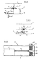
- FIG. 5 shows a view similar to that of Figure 1, except that there is shown in this figure a suspension system 4 subjected to accelerations a x parallel to the plane containing the pivot axes 2,3 and to accelerations a y perpendicular to this plane.
- the counterweight 7 slides on the lower surface 6 of the platform 1 against the action of a spring 8, since it undergoes the effect of acceleration a x .
- This movement of the counterweight 7 in the direction of the inertial forces creates a torque in the counterclockwise direction around the center of gravity 5 of the platform 1, this torque being equal to m (g + a y ) x and a couple clockwise, this torque being equal to ma x l or kxl where k is the constant of the spring 8 and x denotes the displacement of the counterweight 7 with respect to its predetermined position.
- This stabilization device 4 is siliary to that shown in FIG. 5, except that the return spring 8 of the counterweight 7 is fixed to a part 37 subjected to the action of springs 38, this part 37 being movable in a direction perpendicular to the sliding plane 6.
- the part 37 moves perpendicular to the sliding plane 6 against the effect of the spring 38.
- the displacement ⁇ l of this part 37 is equal to where m ⁇ is the mass of the part 37 and k ⁇ is the constant of spring 38.
- FIG. 7 is a partial sectional view of a box similar to that shown in FIG. 4.
- the box 21 differs from cells in FIG. 4 by the fact that the return springs 8 which tend to permanently bring the counterweight 7 to a predetermined position are fixed to annular parts 37.
- the latter can each slide along a rod 39 against the action of a spring 38 in a direction perpendicular to the sliding plane 6 of the counterweight 7.
- This rod 39 has at its ends 40 a threaded part so as to allow the fixing of said rod to the box 21 by means of nuts 41.
- the mass of the annular parts 37 is equal to the mass of the counterweight 7 multiplied by the constant of the spring 38 and divided by the constant of the spring 8.
- pressure forces or forces due to the displacement of a fluid or a mass of cellular rubber can be used as elastic means.
- the device according to the invention thus has the advantage of making it possible to obtain a platform 1 insensitive to horizontal and vertical accelerations, in particular to variable accelerations.
- the device according to the invention has no resonant frequency.
Landscapes
- Engineering & Computer Science (AREA)
- General Engineering & Computer Science (AREA)
- Physics & Mathematics (AREA)
- Acoustics & Sound (AREA)
- Aviation & Aerospace Engineering (AREA)
- Mechanical Engineering (AREA)
- Support Of Aerials (AREA)
- Details Of Aerials (AREA)
Applications Claiming Priority (2)
| Application Number | Priority Date | Filing Date | Title |
|---|---|---|---|
| LU86598 | 1986-09-18 | ||
| LU86598A LU86598A1 (fr) | 1986-09-18 | 1986-09-18 | Dispositif mecanique de stabilisation d'une plate-forme |
Publications (2)
| Publication Number | Publication Date |
|---|---|
| EP0266332A1 true EP0266332A1 (de) | 1988-05-04 |
| EP0266332B1 EP0266332B1 (de) | 1992-06-24 |
Family
ID=19730780
Family Applications (1)
| Application Number | Title | Priority Date | Filing Date |
|---|---|---|---|
| EP19870870128 Expired - Lifetime EP0266332B1 (de) | 1986-09-18 | 1987-09-17 | Mechanische Vorrichtung zum Stabilisieren einer Plattform |
Country Status (3)
| Country | Link |
|---|---|
| EP (1) | EP0266332B1 (de) |
| DE (1) | DE3779995D1 (de) |
| LU (1) | LU86598A1 (de) |
Cited By (1)
| Publication number | Priority date | Publication date | Assignee | Title |
|---|---|---|---|---|
| US12432005B2 (en) | 2023-03-09 | 2025-09-30 | Honeywell International Inc. | Antenna steering through GNSS jamming, spoofing, and airplane maneuvers |
Families Citing this family (1)
| Publication number | Priority date | Publication date | Assignee | Title |
|---|---|---|---|---|
| CN108255202A (zh) * | 2017-12-29 | 2018-07-06 | 南京云清普为通信科技有限公司 | 一种新型寻星装置 |
Citations (1)
| Publication number | Priority date | Publication date | Assignee | Title |
|---|---|---|---|---|
| EP0118729A1 (de) * | 1983-02-14 | 1984-09-19 | Tracor Bei, Inc. | System zur Antennenplattformstabilisierung mit bei Beschleunigung ausgelenkter träger Masse |
-
1986
- 1986-09-18 LU LU86598A patent/LU86598A1/fr unknown
-
1987
- 1987-09-17 DE DE8787870128T patent/DE3779995D1/de not_active Expired - Lifetime
- 1987-09-17 EP EP19870870128 patent/EP0266332B1/de not_active Expired - Lifetime
Patent Citations (1)
| Publication number | Priority date | Publication date | Assignee | Title |
|---|---|---|---|---|
| EP0118729A1 (de) * | 1983-02-14 | 1984-09-19 | Tracor Bei, Inc. | System zur Antennenplattformstabilisierung mit bei Beschleunigung ausgelenkter träger Masse |
Cited By (1)
| Publication number | Priority date | Publication date | Assignee | Title |
|---|---|---|---|---|
| US12432005B2 (en) | 2023-03-09 | 2025-09-30 | Honeywell International Inc. | Antenna steering through GNSS jamming, spoofing, and airplane maneuvers |
Also Published As
| Publication number | Publication date |
|---|---|
| EP0266332B1 (de) | 1992-06-24 |
| LU86598A1 (fr) | 1987-04-02 |
| DE3779995D1 (de) | 1992-07-30 |
Similar Documents
| Publication | Publication Date | Title |
|---|---|---|
| EP0142397B1 (de) | Stabilisierungs- und Richtvorrichtung für Antennen, insbesondere auf Schiffen | |
| FR2569385A1 (fr) | Transfert d'objets en pleine mer | |
| EP0081401A1 (de) | System zur zeitweiligen Festlegung und Freigabe zweier Teile, insbesondere in der Raumfahrttechnik | |
| EP0520872B1 (de) | Vibrationssimulator für Luftschraubenrotor eines Hubschraubers | |
| FR2858680A1 (fr) | Systeme de plate-forme stabilisee | |
| BE1010867A3 (fr) | Base mobile omnidirectionnelle. | |
| EP0266332B1 (de) | Mechanische Vorrichtung zum Stabilisieren einer Plattform | |
| FR2503325A1 (fr) | Monture inclinable a dispositif d'equilibrage, notamment pour cameras | |
| EP0056551B1 (de) | Elastische Mittel für eine mechanische Hebevorrichtung einer Offshore-Plattform | |
| EP0698196B1 (de) | Bildaufnahmevorrichtung mit fernsteuerung | |
| FR2654216A1 (de) | ||
| EP2437981A1 (de) | Landesystem für einen körper und raumsonde mit einem derartigen system | |
| CA2008159A1 (fr) | Dispositif de mise en position inclinee d'une sous-munition sous parachute | |
| FR2476407A1 (fr) | Dispositif de centrage d'un rotor | |
| FR2653219A1 (fr) | Detecteur et procede de detection de verticalite, et base de maintien d'attitude d'un appareil. | |
| EP0056550B1 (de) | Vorrichtung zum Ausrichten nach zwei senkrechten Achsen, insbesondere für eine Mikrowellenantenne | |
| EP1261463A1 (de) | Servogesteuerte lasthandhabungsvorrichtung | |
| FR2589633A1 (fr) | Antenne de pointage du type actif | |
| EP0531220A2 (de) | Vorrichtung, die die Neigung einer Standbildkamera um ihre optische Achse ermöglicht | |
| EP0379415A1 (de) | Verankerungsvorrichtung mit Stabilisierungsteil | |
| EP0052051A1 (de) | Simulator für ein Segelbrett | |
| EP0076194A1 (de) | System zum Ausbalancieren einer Drehmomentunwucht, Anwendung eines solchen Systems für ein auf einem Flugzeug vorgesehenen Radar und durch ein solches System ausbalancierte Antenne | |
| FR2690532A1 (fr) | Dispositif de pointage pour appareil optique. | |
| BE1001867A4 (fr) | Dispositif de cible. | |
| EP3835707B1 (de) | Halterung für persönliche waffe |
Legal Events
| Date | Code | Title | Description |
|---|---|---|---|
| PUAI | Public reference made under article 153(3) epc to a published international application that has entered the european phase |
Free format text: ORIGINAL CODE: 0009012 |
|
| AK | Designated contracting states |
Kind code of ref document: A1 Designated state(s): BE DE ES FR GB |
|
| 17P | Request for examination filed |
Effective date: 19881021 |
|
| 17Q | First examination report despatched |
Effective date: 19910606 |
|
| GRAA | (expected) grant |
Free format text: ORIGINAL CODE: 0009210 |
|
| AK | Designated contracting states |
Kind code of ref document: B1 Designated state(s): BE DE ES FR GB |
|
| PG25 | Lapsed in a contracting state [announced via postgrant information from national office to epo] |
Ref country code: GB Effective date: 19920624 Ref country code: DE Effective date: 19920624 |
|
| REF | Corresponds to: |
Ref document number: 3779995 Country of ref document: DE Date of ref document: 19920730 |
|
| PG25 | Lapsed in a contracting state [announced via postgrant information from national office to epo] |
Ref country code: BE Effective date: 19920930 |
|
| PG25 | Lapsed in a contracting state [announced via postgrant information from national office to epo] |
Ref country code: ES Free format text: LAPSE BECAUSE OF FAILURE TO SUBMIT A TRANSLATION OF THE DESCRIPTION OR TO PAY THE FEE WITHIN THE PRESCRIBED TIME-LIMIT Effective date: 19921005 |
|
| GBV | Gb: ep patent (uk) treated as always having been void in accordance with gb section 77(7)/1977 [no translation filed] |
Effective date: 19920624 |
|
| BERE | Be: lapsed |
Owner name: S.A. SAIT ELECTRONICS Effective date: 19920930 |
|
| PLBE | No opposition filed within time limit |
Free format text: ORIGINAL CODE: 0009261 |
|
| STAA | Information on the status of an ep patent application or granted ep patent |
Free format text: STATUS: NO OPPOSITION FILED WITHIN TIME LIMIT |
|
| PG25 | Lapsed in a contracting state [announced via postgrant information from national office to epo] |
Ref country code: FR Effective date: 19930528 |
|
| 26N | No opposition filed | ||
| REG | Reference to a national code |
Ref country code: FR Ref legal event code: ST |