EP0270097B1 - Body for motor-vehicle - Google Patents
Body for motor-vehicle Download PDFInfo
- Publication number
- EP0270097B1 EP0270097B1 EP87117829A EP87117829A EP0270097B1 EP 0270097 B1 EP0270097 B1 EP 0270097B1 EP 87117829 A EP87117829 A EP 87117829A EP 87117829 A EP87117829 A EP 87117829A EP 0270097 B1 EP0270097 B1 EP 0270097B1
- Authority
- EP
- European Patent Office
- Prior art keywords
- panel
- pair
- vehicle
- longitudinal members
- rear end
- Prior art date
- Legal status (The legal status is an assumption and is not a legal conclusion. Google has not performed a legal analysis and makes no representation as to the accuracy of the status listed.)
- Expired - Lifetime
Links
- 239000002828 fuel tank Substances 0.000 claims description 6
- 239000011521 glass Substances 0.000 claims description 4
- 239000007788 liquid Substances 0.000 claims description 2
- 238000005406 washing Methods 0.000 description 3
- 238000007664 blowing Methods 0.000 description 2
- 238000005516 engineering process Methods 0.000 description 2
- 239000000463 material Substances 0.000 description 1
- 238000000034 method Methods 0.000 description 1
- 238000003466 welding Methods 0.000 description 1
Images



Classifications
-
- B—PERFORMING OPERATIONS; TRANSPORTING
- B62—LAND VEHICLES FOR TRAVELLING OTHERWISE THAN ON RAILS
- B62D—MOTOR VEHICLES; TRAILERS
- B62D43/00—Spare wheel stowing, holding, or mounting arrangements
- B62D43/06—Spare wheel stowing, holding, or mounting arrangements within the vehicle body
- B62D43/10—Spare wheel stowing, holding, or mounting arrangements within the vehicle body and arranged substantially horizontally
-
- B—PERFORMING OPERATIONS; TRANSPORTING
- B60—VEHICLES IN GENERAL
- B60S—SERVICING, CLEANING, REPAIRING, SUPPORTING, LIFTING, OR MANOEUVRING OF VEHICLES, NOT OTHERWISE PROVIDED FOR
- B60S1/00—Cleaning of vehicles
- B60S1/02—Cleaning windscreens, windows or optical devices
- B60S1/46—Cleaning windscreens, windows or optical devices using liquid; Windscreen washers
- B60S1/48—Liquid supply therefor
- B60S1/50—Arrangement of reservoir
-
- B—PERFORMING OPERATIONS; TRANSPORTING
- B62—LAND VEHICLES FOR TRAVELLING OTHERWISE THAN ON RAILS
- B62D—MOTOR VEHICLES; TRAILERS
- B62D25/00—Superstructure or monocoque structure sub-units; Parts or details thereof not otherwise provided for
- B62D25/08—Front or rear portions
- B62D25/087—Luggage compartments
-
- B—PERFORMING OPERATIONS; TRANSPORTING
- B60—VEHICLES IN GENERAL
- B60R—VEHICLES, VEHICLE FITTINGS, OR VEHICLE PARTS, NOT OTHERWISE PROVIDED FOR
- B60R11/00—Arrangements for holding or mounting articles, not otherwise provided for
- B60R11/06—Arrangements for holding or mounting articles, not otherwise provided for for tools or spare parts
Definitions
- the present innovation is related to a body for motor-vehicle, which covers few very simple-shape parts which can be connected between each other through very fast assembly operations, and which can thus be produced at low cost.
- the innovation finding is related to the structure of a body rear end which, as it is well known, usually is very complicated and includes a variety of longitudinal members and crossmembers properly connected between each other, at least a pair of side panels connected to the previous ones, and a platform consisting of more different parts, properly connected between each other and with the previous ones (see i.e. DE-B-2827855).
- the scope of the present innovation is to accomplish a body, and in particular the rear end of the body itself, which includes a few simple-shape parts, suited to be quickly connected between each other and which can therefore be produced at low cost.
- a motor-vehicle body comprising a rear end which includes a pair of side panels, a pair of longitudinal members each of which is adjacent to one of said side panels and is connected to the side panel itself, a pair of crossmembers substantially orthogonal to said longitudinal members of which one is arranged in the rear end and the other is arranged in the central portion of the body, and a plastic panel with a substantially rectangular shape so arranged as to rest on both said longitudinal members and said crossmembers to determine the rear end of the body platform, said panel being as least provided with a recess suited to accommodate a spare wheel and a further recess suited to accommodate a fuel tank.
- the panel can also include further recesses 8 and 9, the former suited to originate the housings for the vehicle's tool kit and the latter to originate a liquid reservoir for the glass washing device.
- the panel 5 and its cover 10 can be obtained through a blowing technology from a single plastic piece by using, for instance, the usual forming technologies through blowing.
- the panel 5 presents a rear edge 11, substantially bent into box-like shape and so arranged as to rest on the rear crossmember to originate the rear bumper of the motor-vehicle.
- the panel 5 can include a seat 12 obtained from a single piece with the panel 5 can include a seat 12 obtained from a single piece with the panel itself; in this case, the seat will have a structure as to be obtained through the same process as the one through which the panel itself is obtained and is connected to the latter by a deformable bridge 13, directly obtained from the local forming of the panel 5.
- the seat is in the configuration shown on Fig. 11 and can be rotated around the bridge 13 in order to take it back to its employment position, as shown in Fig. 9.
- the rear portion of the body accomplished as indicated has a very simple structure and can be built at low cost though resulting in a sturdy and reliable structure.
- the four-side structure accomplished through the assembly of the longitudinal members 2 and crossmembers 3 and 4 shows a high strength and represents an effective support for the panel 5, which is placed on them and forms the vehicle's rear platform, already provided with the seats where the fuel tank, the spare wheel, the glass washing device and the vehicle's tool kit are to be placed.
- the bumper can be accomplished in a very simple way by using partly the material of panel 5 (rear edge bent 11), and partly the body (rear crossmember 4): from the combination of such two structural elements there comes out a bumper which shows high deformability, due to the box-type rear edge 11, and a high strength due to the rear crossmember 4.
- the parts making up the rear portion of the body can be joined between each other in a simple and quick way by accomplishing, first the structure with a mechanical strength function, made by the longitudinal members 2, the crossmembers 3 and 4 and the side panels 1, such parts being connected between each other through regular welding operations; aside, a unit can be prepared which consists of panel 5, and those parts and devices that shall be supported by the panel itself (fuel tank, glass washing device, covering sheet, and the like). Such a unit can subsequently rest on the longitudinal members and crossmembers and locked in a whatever suitable way.
Landscapes
- Engineering & Computer Science (AREA)
- Mechanical Engineering (AREA)
- Chemical & Material Sciences (AREA)
- Combustion & Propulsion (AREA)
- Transportation (AREA)
- Water Supply & Treatment (AREA)
- Cooling, Air Intake And Gas Exhaust, And Fuel Tank Arrangements In Propulsion Units (AREA)
- Body Structure For Vehicles (AREA)
Description
- The present innovation is related to a body for motor-vehicle, which covers few very simple-shape parts which can be connected between each other through very fast assembly operations, and which can thus be produced at low cost.
- In particular, the innovation finding is related to the structure of a body rear end which, as it is well known, usually is very complicated and includes a variety of longitudinal members and crossmembers properly connected between each other, at least a pair of side panels connected to the previous ones, and a platform consisting of more different parts, properly connected between each other and with the previous ones (see i.e. DE-B-2827855).
- Because of both the high number of parts making up the rear portion of a body and the complexity of assembly operations necessary to connect between each other said parts,the cost of a conventional body of the type shown proves to be rather high.
- The scope of the present innovation is to accomplish a body, and in particular the rear end of the body itself, which includes a few simple-shape parts, suited to be quickly connected between each other and which can therefore be produced at low cost.
- Such a scope is fulfilled through a motor-vehicle body comprising a rear end which includes a pair of side panels, a pair of longitudinal members each of which is adjacent to one of said side panels and is connected to the side panel itself, a pair of crossmembers substantially orthogonal to said longitudinal members of which one is arranged in the rear end and the other is arranged in the central portion of the body, and a plastic panel with a substantially rectangular shape so arranged as to rest on both said longitudinal members and said crossmembers to determine the rear end of the body platform, said panel being as least provided with a recess suited to accommodate a spare wheel and a further recess suited to accommodate a fuel tank.
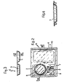
- For a better understanding of the finding referred to in the present innovation, a more detailed description of it will be given as a way of example with reference to the attached drawings, where:
- Fig. 1 represents a pictorial view of a body rear end built according to the present innovation;
- Fig. 2 represents a plan view of the portion shown in Fig. 1;
- Fig. 3 represents a schematic section of the body referred to in Fig. 2 carried out by a III-III intersecting plane;
- Fig. 4 represents a cross section of the body portion referred to in Fig. 3 carried out by a IV-IV intersecting plane;
- Fig. 5 represents a plan view of an additional accomplishment form according to the present innovation;
- Fig. 6 is a schematic section of the Fig. 5 accomplishment carried out by a VI-VI intersecting plane;
- Fig. 7 is a section of the body portion referred to in Fig. 6 carried out by a VII-VII intersecting plane;
- Fig. 8 represents a plan view of a third accomplishment form according to the present innovation;
- Fig. 9 is a schematic section of the body referred to in Fig. 8 carried out by a IX-IX intersecting plane;
- Fig. 10 is a section of the body portion referred to in Fig. 9 carried out by an X-X intersecting plane;
- Fig. 11 is a schematic developed section of the body referred to in Fig. 9
- The panel can also include
further recesses - The panel 5 and its
cover 10 can be obtained through a blowing technology from a single plastic piece by using, for instance, the usual forming technologies through blowing. - In a additional form of accomplishment shown in Figs. 5 through 7, the panel 5 presents a
rear edge 11, substantially bent into box-like shape and so arranged as to rest on the rear crossmember to originate the rear bumper of the motor-vehicle. - In a further form of accomplishment according to Figures from 8 through 11, the panel 5 can include a
seat 12 obtained from a single piece with the panel 5 can include aseat 12 obtained from a single piece with the panel itself; in this case, the seat will have a structure as to be obtained through the same process as the one through which the panel itself is obtained and is connected to the latter by adeformable bridge 13, directly obtained from the local forming of the panel 5. - Thus after the forming operation, the seat is in the configuration shown on Fig. 11 and can be rotated around the
bridge 13 in order to take it back to its employment position, as shown in Fig. 9. - Obviously, the rear portion of the body accomplished as indicated has a very simple structure and can be built at low cost though resulting in a sturdy and reliable structure.
- In fact, the four-side structure accomplished through the assembly of the
longitudinal members 2 andcrossmembers 3 and 4 shows a high strength and represents an effective support for the panel 5, which is placed on them and forms the vehicle's rear platform, already provided with the seats where the fuel tank, the spare wheel, the glass washing device and the vehicle's tool kit are to be placed. Finally, the bumper can be accomplished in a very simple way by using partly the material of panel 5 (rear edge bent 11), and partly the body (rear crossmember 4): from the combination of such two structural elements there comes out a bumper which shows high deformability, due to the box-typerear edge 11, and a high strength due to the rear crossmember 4. - The parts making up the rear portion of the body, can be joined between each other in a simple and quick way by accomplishing, first the structure with a mechanical strength function, made by the
longitudinal members 2, thecrossmembers 3 and 4 and the side panels 1, such parts being connected between each other through regular welding operations; aside, a unit can be prepared which consists of panel 5, and those parts and devices that shall be supported by the panel itself (fuel tank, glass washing device, covering sheet, and the like). Such a unit can subsequently rest on the longitudinal members and crossmembers and locked in a whatever suitable way. - Obviously, changes and variations can be made to the shape and arrangement of the various parts referred to in the finding, without however coming out of the innovation domain.
With reference to Fig. 1, the rear portion of the model body includes two side panels 1, two
Claims (4)
- Body for a motor-vehicle comprising a rear end which includes a pair of side panels (1), a pair of longitudinal members (2) each of which is close to a pair of such side panels and is connected to the latter, a pair of crossmembers (3,4) substantially orthogonal to said longitudinal members one of which is arranged at the rear end and the other is arranged in the central portion of the body and a plastic panel (5) of substantially rectangular shape so arranged as to rest on said longitudinal members and said crossmembers to determine the rear end of the body platform, such a panel being provided with at least a first recess (6) suited to originate a housing for a spare wheel and a further recess (7) suited to originate a housing for a fuel tank.
- Body according to the claim 1 characterized by the fact that such a panel shows a rear edge (11) bent into a box-like shape and so arranged as to rest on said crossmember to originate the vehicle's rear bumper.
- Body according to the claim 1 characterized by the fact that on said panel further recesses (8,9) are obtained for the vehicle's tool kit and for the reservoir of the glass washer liquid.
- Body according to one of the above claims, characterized by the fact that such a panel includes a seat (12) obtained from a single piece with the panel itself, said seat being connected to said panel by a deformable bridge (13), directly obtained from the panel, so as to be able to tilt over such a seat rotating it around said bridge and also to bring it over said panel into the employment position.
Applications Claiming Priority (2)
| Application Number | Priority Date | Filing Date | Title |
|---|---|---|---|
| IT8654169U IT208484Z2 (en) | 1986-12-05 | 1986-12-05 | BODYWORK FOR A VEHICLE |
| IT5416986U | 1986-12-05 |
Publications (2)
| Publication Number | Publication Date |
|---|---|
| EP0270097A1 EP0270097A1 (en) | 1988-06-08 |
| EP0270097B1 true EP0270097B1 (en) | 1991-05-02 |
Family
ID=11286853
Family Applications (1)
| Application Number | Title | Priority Date | Filing Date |
|---|---|---|---|
| EP87117829A Expired - Lifetime EP0270097B1 (en) | 1986-12-05 | 1987-12-02 | Body for motor-vehicle |
Country Status (5)
| Country | Link |
|---|---|
| EP (1) | EP0270097B1 (en) |
| BR (1) | BR8706473A (en) |
| DE (1) | DE3769764D1 (en) |
| ES (1) | ES2022278B3 (en) |
| IT (1) | IT208484Z2 (en) |
Cited By (1)
| Publication number | Priority date | Publication date | Assignee | Title |
|---|---|---|---|---|
| DE102004007037B4 (en) * | 2004-02-12 | 2009-02-26 | Daimler Ag | motor vehicle |
Families Citing this family (13)
| Publication number | Priority date | Publication date | Assignee | Title |
|---|---|---|---|---|
| AT389681B (en) * | 1988-06-22 | 1990-01-10 | Steyr Daimler Puch Ag | FLOORING FOR MOTOR VEHICLES, ESPECIALLY CAB |
| FR2684950B1 (en) * | 1991-12-12 | 1996-03-22 | Chausson Ingenierie | MULTI - FUNCTION SERVICE MODULE FOR MOTOR VEHICLES. |
| DE4420439A1 (en) * | 1994-06-10 | 1995-12-14 | Stankiewicz Gmbh | Loading area lining with integrated sound insulation |
| FR2773132B1 (en) * | 1997-12-30 | 2000-01-21 | Renault | ASSEMBLY METHOD AND FLOOR STRUCTURE FOR MOTOR VEHICLES |
| DE19841100C1 (en) * | 1998-09-09 | 2000-04-13 | Daimler Chrysler Ag | Rear structure of a self-supporting motor vehicle body and method for its production |
| FR2798640B1 (en) * | 1999-09-16 | 2001-11-23 | Inoplast Sa | REAR FLOORING STRUCTURE AND METHOD FOR MANUFACTURING A MOTOR VEHICLE INCORPORATING SUCH A STRUCTURE |
| DE19950165B4 (en) * | 1999-10-19 | 2004-04-08 | Daimlerchrysler Ag | Automotive body |
| FR2805514B1 (en) * | 2000-02-24 | 2002-05-31 | Plastic Omnium Cie | REAR MODULE FOR MOTOR VEHICLE |
| FR2852571B1 (en) * | 2003-03-19 | 2005-05-27 | BAC FOR EMERGENCY WHEEL AND REAR STRUCTURE OF VEHICLE COMPRISING SAID BIT. | |
| JP4167931B2 (en) | 2003-04-24 | 2008-10-22 | ダイキョーニシカワ株式会社 | Resin floor panel structure |
| JP4205477B2 (en) * | 2003-04-24 | 2009-01-07 | ダイキョーニシカワ株式会社 | Resin floor panel structure |
| JP4347370B2 (en) * | 2007-08-02 | 2009-10-21 | 本田技研工業株式会社 | Parcel shelf structure at the rear of the car body |
| FR2950851A1 (en) * | 2009-10-05 | 2011-04-08 | Renault Sas | Structure for motor vehicle, has synthetic material container including ledge support on floor surfaces and on face of rear cross member, where container arranged between two longerons |
Family Cites Families (5)
| Publication number | Priority date | Publication date | Assignee | Title |
|---|---|---|---|---|
| US4093088A (en) * | 1977-05-12 | 1978-06-06 | General Motors Corporation | Underfloor tire storage |
| DE2827855C2 (en) * | 1978-06-24 | 1986-08-21 | Adam Opel AG, 6090 Rüsselsheim | Arrangement of the spare wheel in motor vehicles, in particular passenger vehicles |
| DE2840689B2 (en) * | 1978-09-19 | 1980-07-10 | Adam Opel Ag, 6090 Ruesselsheim | Rear section of a motor vehicle body, in particular of a passenger vehicle |
| DE3339415A1 (en) * | 1983-10-29 | 1985-05-23 | Audi AG, 8070 Ingolstadt | Cover plate for a luggage compartment or a recess for a spare wheel of a vehicle |
| DE3531543A1 (en) * | 1984-09-12 | 1986-03-20 | Volkswagen AG, 3180 Wolfsburg | Holder of a spare wheel pan on a vehicle floor |
-
1986
- 1986-12-05 IT IT8654169U patent/IT208484Z2/en active
-
1987
- 1987-11-24 BR BR8706473A patent/BR8706473A/en not_active IP Right Cessation
- 1987-12-02 ES ES87117829T patent/ES2022278B3/en not_active Expired - Lifetime
- 1987-12-02 DE DE8787117829T patent/DE3769764D1/en not_active Expired - Fee Related
- 1987-12-02 EP EP87117829A patent/EP0270097B1/en not_active Expired - Lifetime
Cited By (1)
| Publication number | Priority date | Publication date | Assignee | Title |
|---|---|---|---|---|
| DE102004007037B4 (en) * | 2004-02-12 | 2009-02-26 | Daimler Ag | motor vehicle |
Also Published As
| Publication number | Publication date |
|---|---|
| IT8654169V0 (en) | 1986-12-05 |
| EP0270097A1 (en) | 1988-06-08 |
| ES2022278B3 (en) | 1991-12-01 |
| BR8706473A (en) | 1989-06-20 |
| DE3769764D1 (en) | 1991-06-06 |
| IT208484Z2 (en) | 1988-05-28 |
Similar Documents
| Publication | Publication Date | Title |
|---|---|---|
| EP0270097A1 (en) | Body for motor-vehicle | |
| US4549786A (en) | Mirror assembly | |
| CA2032328C (en) | Foldable vehicle outside rearview mirror having a detachable cap | |
| US8782845B2 (en) | Wiper blade comprising a support mount, an internal verterbra and a connecting element | |
| KR100370342B1 (en) | Pivot mount for mirrors after external side mounting | |
| USD297228S (en) | Sunshield for motor vehicle windscreen | |
| EP0083701A3 (en) | Instrument mounting dashboard, particularly for motor vehicles | |
| US4307865A (en) | Universal tractor seat | |
| EP0776789A2 (en) | Automobile instrument panel harness-connecting construction | |
| DE3767740D1 (en) | SEAT, IN PARTICULAR FOR A MOTOR VEHICLE. | |
| DE69007396D1 (en) | Rear wheel steering for a vehicle. | |
| DE69013221D1 (en) | Auxiliary board on the dashboard of a motor vehicle. | |
| US5332277A (en) | Bearer joint for vehicle bodywork | |
| US3702510A (en) | License plate support and pivotable cover member | |
| US5871207A (en) | Damper means | |
| ES1014089U (en) | Automobile accessory with panels indicators to ask for help. (Machine-translation by Google Translate, not legally binding) | |
| DE69012297D1 (en) | Rear wheel steering angle test circuit for vehicles. | |
| US4352510A (en) | Support bracket | |
| US4023838A (en) | Work vehicle protective cover | |
| JP2000001180A (en) | Cowl structure | |
| EP0306093A1 (en) | Composite folding sheet | |
| KR200147090Y1 (en) | Wheel house exact position setting device for inspection of engine room of automobile | |
| JPS6328820B2 (en) | ||
| JPS6218868Y2 (en) | ||
| CN221340862U (en) | Front end module's location structure and vehicle |
Legal Events
| Date | Code | Title | Description |
|---|---|---|---|
| PUAI | Public reference made under article 153(3) epc to a published international application that has entered the european phase |
Free format text: ORIGINAL CODE: 0009012 |
|
| AK | Designated contracting states |
Kind code of ref document: A1 Designated state(s): DE ES FR GB SE |
|
| 17P | Request for examination filed |
Effective date: 19881124 |
|
| 17Q | First examination report despatched |
Effective date: 19900731 |
|
| GRAA | (expected) grant |
Free format text: ORIGINAL CODE: 0009210 |
|
| AK | Designated contracting states |
Kind code of ref document: B1 Designated state(s): DE ES FR GB SE |
|
| REF | Corresponds to: |
Ref document number: 3769764 Country of ref document: DE Date of ref document: 19910606 |
|
| ET | Fr: translation filed | ||
| PLBE | No opposition filed within time limit |
Free format text: ORIGINAL CODE: 0009261 |
|
| STAA | Information on the status of an ep patent application or granted ep patent |
Free format text: STATUS: NO OPPOSITION FILED WITHIN TIME LIMIT |
|
| 26N | No opposition filed | ||
| PGFP | Annual fee paid to national office [announced via postgrant information from national office to epo] |
Ref country code: SE Payment date: 19931108 Year of fee payment: 7 |
|
| PGFP | Annual fee paid to national office [announced via postgrant information from national office to epo] |
Ref country code: ES Payment date: 19931117 Year of fee payment: 7 |
|
| PGFP | Annual fee paid to national office [announced via postgrant information from national office to epo] |
Ref country code: GB Payment date: 19931129 Year of fee payment: 7 |
|
| PG25 | Lapsed in a contracting state [announced via postgrant information from national office to epo] |
Ref country code: GB Effective date: 19941202 |
|
| PG25 | Lapsed in a contracting state [announced via postgrant information from national office to epo] |
Ref country code: SE Effective date: 19941203 |
|
| EAL | Se: european patent in force in sweden |
Ref document number: 87117829.9 |
|
| GBPC | Gb: european patent ceased through non-payment of renewal fee |
Effective date: 19941202 |
|
| EUG | Se: european patent has lapsed |
Ref document number: 87117829.9 |
|
| PG25 | Lapsed in a contracting state [announced via postgrant information from national office to epo] |
Ref country code: ES Free format text: LAPSE BECAUSE OF NON-PAYMENT OF DUE FEES Effective date: 19951203 |
|
| PGFP | Annual fee paid to national office [announced via postgrant information from national office to epo] |
Ref country code: FR Payment date: 19961119 Year of fee payment: 10 |
|
| PGFP | Annual fee paid to national office [announced via postgrant information from national office to epo] |
Ref country code: DE Payment date: 19961231 Year of fee payment: 10 |
|
| PG25 | Lapsed in a contracting state [announced via postgrant information from national office to epo] |
Ref country code: FR Free format text: THE PATENT HAS BEEN ANNULLED BY A DECISION OF A NATIONAL AUTHORITY Effective date: 19971231 |
|
| PG25 | Lapsed in a contracting state [announced via postgrant information from national office to epo] |
Ref country code: DE Free format text: LAPSE BECAUSE OF NON-PAYMENT OF DUE FEES Effective date: 19980901 |
|
| REG | Reference to a national code |
Ref country code: FR Ref legal event code: ST |
|
| REG | Reference to a national code |
Ref country code: ES Ref legal event code: FD2A Effective date: 19960113 |