EP0271899B1 - Automatic heating appliance with identifying function of an object to be heated - Google Patents
Automatic heating appliance with identifying function of an object to be heated Download PDFInfo
- Publication number
- EP0271899B1 EP0271899B1 EP87118683A EP87118683A EP0271899B1 EP 0271899 B1 EP0271899 B1 EP 0271899B1 EP 87118683 A EP87118683 A EP 87118683A EP 87118683 A EP87118683 A EP 87118683A EP 0271899 B1 EP0271899 B1 EP 0271899B1
- Authority
- EP
- European Patent Office
- Prior art keywords
- heating
- sensor
- heating chamber
- heating appliance
- appliance
- Prior art date
- Legal status (The legal status is an assumption and is not a legal conclusion. Google has not performed a legal analysis and makes no representation as to the accuracy of the status listed.)
- Expired - Lifetime
Links
Images


Classifications
-
- H—ELECTRICITY
- H05—ELECTRIC TECHNIQUES NOT OTHERWISE PROVIDED FOR
- H05B—ELECTRIC HEATING; ELECTRIC LIGHT SOURCES NOT OTHERWISE PROVIDED FOR; CIRCUIT ARRANGEMENTS FOR ELECTRIC LIGHT SOURCES, IN GENERAL
- H05B6/00—Heating by electric, magnetic or electromagnetic fields
- H05B6/02—Induction heating
- H05B6/10—Induction heating apparatus, other than furnaces, for specific applications
- H05B6/12—Cooking devices
-
- F—MECHANICAL ENGINEERING; LIGHTING; HEATING; WEAPONS; BLASTING
- F24—HEATING; RANGES; VENTILATING
- F24C—DOMESTIC STOVES OR RANGES ; DETAILS OF DOMESTIC STOVES OR RANGES, OF GENERAL APPLICATION
- F24C7/00—Stoves or ranges heated by electric energy
- F24C7/08—Arrangement or mounting of control or safety devices
-
- F—MECHANICAL ENGINEERING; LIGHTING; HEATING; WEAPONS; BLASTING
- F24—HEATING; RANGES; VENTILATING
- F24C—DOMESTIC STOVES OR RANGES ; DETAILS OF DOMESTIC STOVES OR RANGES, OF GENERAL APPLICATION
- F24C7/00—Stoves or ranges heated by electric energy
- F24C7/02—Stoves or ranges heated by electric energy using microwaves
-
- H—ELECTRICITY
- H05—ELECTRIC TECHNIQUES NOT OTHERWISE PROVIDED FOR
- H05B—ELECTRIC HEATING; ELECTRIC LIGHT SOURCES NOT OTHERWISE PROVIDED FOR; CIRCUIT ARRANGEMENTS FOR ELECTRIC LIGHT SOURCES, IN GENERAL
- H05B6/00—Heating by electric, magnetic or electromagnetic fields
- H05B6/64—Heating using microwaves
- H05B6/6447—Method of operation or details of the microwave heating apparatus related to the use of detectors or sensors
-
- H—ELECTRICITY
- H05—ELECTRIC TECHNIQUES NOT OTHERWISE PROVIDED FOR
- H05B—ELECTRIC HEATING; ELECTRIC LIGHT SOURCES NOT OTHERWISE PROVIDED FOR; CIRCUIT ARRANGEMENTS FOR ELECTRIC LIGHT SOURCES, IN GENERAL
- H05B6/00—Heating by electric, magnetic or electromagnetic fields
- H05B6/64—Heating using microwaves
- H05B6/66—Circuits
- H05B6/68—Circuits for monitoring or control
- H05B6/687—Circuits for monitoring or control for cooking
Definitions
- the present invention relates generally to automatic heating appliances, and more particularly to such an automatic heating appliance for controlling the heating temperature of an object in accordance with the kind of the object.
- the present invention is applicable particularly, but not exclusively, to an oven for cooking a food.
- Document EP-A-0 166 997 encloses a heating appliance with a heating chamber wherein there are provided heating means for heating an object which is encased within the heating chamber and table means provided within the heating chamber on which the object is placed.
- a weight sensor measures the weight of an object and a state detecting sensor detects the heated state of said object. The heat is controlled on the basis of the weight of the object and the detection of a humidity sensor.
- Document JP-A-61 186 725 discloses a technique wherein a height sensor comprising plural pairs of light-emitting elements and light-receiving elements disposed vertically at the walls of the heating chamber is provided to measure the height of an object , and a movable heater is provided and operated by an adjustment drive device. Furthermore, the use of an ultrasonic sensor instead of a height sensor is disclosed.
- Document DE-U-8 434 370 describes a heating appliance wherein rack means are arranged stepwise within the heating chamber in order to provide an insert of different heights for table means.
- heating appliances such as electric oven and gas oven for heating an object with elevation of the temperature of air within a heating chamber and convection of the temperature-increased air.
- a heating appliance generally has a plurality of keys on an operating pannel, which are operated in accordance with the kind, or class, of the object to be heated within the heating chamber because the cooking time period and heating temperature are respectively different in accordance with the class of the object.
- the cooking time period and the heating temperature are respectively selected by different keys and one of a plurality of racks provided within the heating chamber is selected in accordance with the class of the object to be heated so as to obtain a desired heat distribution.
- the selection of the keys results in being troublesome for users and the error of selection of one of the plurality of racks causes failure of cooking of the object, and hence improvement would be required from the viewpoint of simplification of handing of the appliance and prevention of the cooking failure.
- the present invention has been developed in order to eliminate the above-mentioned drawbacks inherent to the conventional heating appliances.
- a feature of an automatic heating appliance is to detect the class of an object to be heated on the basis of the position of the object within a heating chamber or state of gas generated from the object in response to heating and automatically control the heating temperature of the object in accordance with the class of the object, resulting in reduction of the number of operating keys for cooking instruction and simplification of operation of the appliance.
- a heating appliance with a heating chamber for encasing an object to be heated comprising heating means provided for heating said object, table means provided at a predetermined height position within said heating chamber, and first sensor means for sensing an amount of vapor and/or gas generated from said object, said heating appliance being characterized by second sensor means provided at an upper portion of the heating chamber for measuring a distance to the object or the table means; and control means coupled to the second sensor means to be responsive to a detection signal indicative of the distance to the object or the table means to determine a position of the table means within the heating chamber and further coupled to the first sensor means to be responsive to a detection signal indicative of an amount of the vapor and/or gas generated from the object, the control means determining the kind of the object on the basis of detection signals from the first and second sensor means in accordance with a curve by the plotting of the outputs of said first sensor means so as to control a feed to the heating means in accordance with the determined kind of the object.
- FIG. 7 there is illustrated an arrangement of an automatic heating appliance according to an embodiment of the present invention.
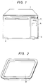
- a heating instruction is transmitted to a control section 5 through a full-automation key 4 on an operating pannel 3 which are illustrated in Fig. 1 which is a perspective view showing the external appearance of the automatic heating appliance and wherein numerals 1 and 2 represent a housing and a door of the appliance, respectively.
- the control section 5 may comprise comprising a known microcomputer with a central processing unit (CPU) and memories, energizes a distance-measuring sensor 6 through a drive and detection circuit 18 so as to measure the distance D to a table 8 on which an object 7 is placed, the distance-measuring sensor being provided on the ceiling of a heating chamber 9.
- the heating chamber 9 Within the heating chamber 9 are stepwise provided pairs of rack rails 10, one of which is selected in accordance with the class of the object 7.
- the upper rack rails 10 are used for cooking of a cookie
- the middle rack rails 10 are used for cooking of a bread and a chou
- the lower rack rails 10 are used for cooking of a cake.
- the desired position may be determined in accordance with the arrangement of the heating chamber 9, i.e., heat distribution and so on.
- the distance-measuring sensor 6 measures the distance D to the table 8 and this distance measurement allows detection of the position of the table 8, which may be arranged as illustrated in Fig. 2 such that its flange-portions are placed on the pair of the rack rails 10.
- the detection of the position of the table 8 further allows estimation of the kind of the object 7.
- the result of the estimation is indicated on a display section 11 as shown in Fig. 3, the display section 12 comprising a class-indicating portion 14 and further time-indicating portion 12 and temperature-indicating portion 13.
- the indication of the class of the object 7 to be heated allows confirmation of the class of the object 7 by the user.
- the control section 5 energizes upper and lower heaters 16 through a driver 15 so as to obtain a heating temperature corresponding to the class of the object 7 specified by the user.
- the heaters 16 may be of the electric type or gas type.
- the temperature within the heating chamber 9 is sensed by means of a temperature sensor 17 and the sensed temperature information is supplied through a detection circuit 19 with an analog-to-digital converter to the control section 5 which in turn controls the power supply to the heaters 16, i.e., distribution of the power supply to the upper and lower heaters 16 and the heating time, in accordance with the appointed object class.
- Fig. 4 is a time chart illustrating one example of methods of power supply to the upper and lower heaters 16 and controlled temperature obtained as the result of the power supply.
- the temperature is controllable by control of the energizing time period Tu to the upper heater 16 and the energizing time period Td to the lower heater 16.
- the heating temperature * is controlled to 160°C when the object 7 is a cookie and to 180 ° C when it is a puff.
- the overall heating time period T is determined in accordance with the class of the object 7. For example, the time period T is set to 15 minutes when it is a cookie and to 25 minutes when it is a puff.
- Fig. 5 is a cross-sectional view showing one example of ultrasonic sensor usable as the distance-measuring sensor 6.
- the distance-measuring sensor 6 is not limited to the above-mentioned ultrasonic sensor, but other sensors such as infrared sensor are applicable thereto.
- Fig. 6 is a block diagram showing one example of arrangements of the drive and detection circuit 18.
- the drive and detection circuit 18 comprises a transmitting circuit 29 and a receiving circuit 30.
- the transmitting circuit 29 drives the distance-measuring sensor 6 in response to a timing control signal from the control section 5 and the receiving circuit 30 receives an output signal of the distance-measuring sensor 6 corresponding to the echo wave returning from the object 7.
- the output signal of the receiving circuit 30 is supplied to a comparator 31 where the output signal of the receiving circuit 30 is compared with a reference signal.
- the output signal thereof When level of the output signal thereof exceeds the level of the reference signal, the output signal thereof is latched and supplied to a data-processing portion of the control section 5.
- the control section 5 counts the time period from the transmission to the reception and calculates the distance to the table 8 or the object 7 on the basis of the propagating time of the ultrasonic wave and then to detect the position of the table 8 and the height of the object 7.
- the detection of the height of the object 7 allows discrimination of the kind of the object 7 even if the table 8 takes the same position. That is, at the time of the start of heating, the chou is lower in height and the bread is higher in height. Furthermore, since the condition of expansion of the object 7 can be detected, it is possible to determine the kind of the object 7 on the basis of the condition of the expansion.
- FIG. 7 there is shown an illustration of the automatic heating appliance, which is arranged so that the class of the object 7 to be heated is determined on the basis of the position of the object-mounting table 8 and the generating state of vapor or gas from the object 7.
- the control section 5 starts heating of the object 7 placed on the table 8 positioned by rack rails 10 arranged within the heating chamber 9.
- the heating causes generation of vapor or gas from the object 7.
- the generated vapor or gas is detected by a gas sensor 32 which is located at the side wall of the heating chamber 9.
- the gas sensor 32 may be a humidity sensor in this embodiment and the gas sensor 32 and the detection circuit 33 can be realized in accordance with the description in Japanese Patent Provisional Publication No.
- Fig. 8 is a time chart showing a method of determination of the class of the object 7, in which vertical axis represents variation of the output of the sensor 32, i.e., absolute humidity, and the horizontal axis represents elapsed time. As understood from Fig.
- the gas-generating state is varied in accordance with the kind of the object 7 and therefore the kind of the object 7 can be determined by detection of the gas-generating state even if the table 8 takes the same position.
- the control section 5 plots the outputs of the gas sensor 32 with respect to time and determines the kind of the object 7 in accordance with a curve formed by the plotting of the outputs. For example, even if the cooking is started as a cake in spite of the object 7 being a bread, since the kind of the object 7 can be determined in accordance with the gas-generating state, the cooking error can be removed by changing the heating temperature at the time of the determination of the kind of the object 7.
Landscapes
- Engineering & Computer Science (AREA)
- Electromagnetism (AREA)
- Physics & Mathematics (AREA)
- General Engineering & Computer Science (AREA)
- Combustion & Propulsion (AREA)
- Mechanical Engineering (AREA)
- Chemical & Material Sciences (AREA)
- Electric Ovens (AREA)
- Control Of Resistance Heating (AREA)
- Electric Stoves And Ranges (AREA)
- Measurement Of Levels Of Liquids Or Fluent Solid Materials (AREA)
- Special Spraying Apparatus (AREA)
- Length Measuring Devices Characterised By Use Of Acoustic Means (AREA)
- Control Of High-Frequency Heating Circuits (AREA)
Description
- The present invention relates generally to automatic heating appliances, and more particularly to such an automatic heating appliance for controlling the heating temperature of an object in accordance with the kind of the object. The present invention is applicable particularly, but not exclusively, to an oven for cooking a food.
- Document EP-A-0 166 997 encloses a heating appliance with a heating chamber wherein there are provided heating means for heating an object which is encased within the heating chamber and table means provided within the heating chamber on which the object is placed. A weight sensor measures the weight of an object and a state detecting sensor detects the heated state of said object. The heat is controlled on the basis of the weight of the object and the detection of a humidity sensor.
- Document JP-A-61 186 725 discloses a technique wherein a height sensor comprising plural pairs of light-emitting elements and light-receiving elements disposed vertically at the walls of the heating chamber is provided to measure the height of an object , and a movable heater is provided and operated by an adjustment drive device. Furthermore, the use of an ultrasonic sensor instead of a height sensor is disclosed.
- Document DE-U-8 434 370 describes a heating appliance wherein rack means are arranged stepwise within the heating chamber in order to provide an insert of different heights for table means.
- Furthermore, there are known heating appliances such as electric oven and gas oven for heating an object with elevation of the temperature of air within a heating chamber and convection of the temperature-increased air. Such a heating appliance generally has a plurality of keys on an operating pannel, which are operated in accordance with the kind, or class, of the object to be heated within the heating chamber because the cooking time period and heating temperature are respectively different in accordance with the class of the object. The cooking time period and the heating temperature are respectively selected by different keys and one of a plurality of racks provided within the heating chamber is selected in accordance with the class of the object to be heated so as to obtain a desired heat distribution. The selection of the keys results in being troublesome for users and the error of selection of one of the plurality of racks causes failure of cooking of the object, and hence improvement would be required from the viewpoint of simplification of handing of the appliance and prevention of the cooking failure.
- The present invention has been developed in order to eliminate the above-mentioned drawbacks inherent to the conventional heating appliances.
- It is therefore an object of the present invention to provide a new and improved automatic heating appliance which is capable of automatically and appropriately controlling the heating temperature by discriminating the kind of an object to be heated.
- A feature of an automatic heating appliance according to the present invention is to detect the class of an object to be heated on the basis of the position of the object within a heating chamber or state of gas generated from the object in response to heating and automatically control the heating temperature of the object in accordance with the class of the object, resulting in reduction of the number of operating keys for cooking instruction and simplification of operation of the appliance.
- According to the invention there is provided a heating appliance with a heating chamber for encasing an object to be heated comprising heating means provided for heating said object, table means provided at a predetermined height position within said heating chamber, and first sensor means for sensing an amount of vapor and/or gas generated from said object, said heating appliance being characterized by second sensor means provided at an upper portion of the heating chamber for measuring a distance to the object or the table means; and control means coupled to the second sensor means to be responsive to a detection signal indicative of the distance to the object or the table means to determine a position of the table means within the heating chamber and further coupled to the first sensor means to be responsive to a detection signal indicative of an amount of the vapor and/or gas generated from the object, the control means determining the kind of the object on the basis of detection signals from the first and second sensor means in accordance with a curve by the plotting of the outputs of said first sensor means so as to control a feed to the heating means in accordance with the determined kind of the object.
- The object and features of the present invention will become more readily apparent from the following detailed description of the preferred embodiments taken in conjunction with the accompanying drawings in which:
- Fig. 1 is a perspective view showing the external form of the automatic heating appliance according to the invention;
- Fig. 2 is a perspective view illustrating a table on which an object to be heated is placed;
- Fig. 3 is an illustration of an indicator of the automatic heating appliance of the invention;
- Fig. 4 is a graphic diagram for describing a heating temperature control method of the invention;
- Fig. 5 is a cross-sectional view showing an ultrasonic sensor used in the automatic heating appliance of the invention;
- Fig. 6 is a block diagram showing a drive and detection circuit to be provided for drive of the ultrasonic sensor of Fig. 5 and reception of signals from the ultrasonic sensor;
- Fig. 7 is a block diagram showing an arrangement of an automatic heating appliance according to an embodiment of the present invention; and
- Fig. 8 is graphic illustration for describing variation of the generating state of gas in accordance with the kind of an object.
- Referring now to Fig. 7, there is illustrated an arrangement of an automatic heating appliance according to an embodiment of the present invention. In Fig. 7, a heating instruction is transmitted to a
control section 5 through a full-automation key 4 on anoperating pannel 3 which are illustrated in Fig. 1 which is a perspective view showing the external appearance of the automatic heating appliance and whereinnumerals control section 5, maybe comprising a known microcomputer with a central processing unit (CPU) and memories, energizes a distance-measuring sensor 6 through a drive anddetection circuit 18 so as to measure the distance D to a table 8 on which anobject 7 is placed, the distance-measuring sensor being provided on the ceiling of aheating chamber 9. Within theheating chamber 9 are stepwise provided pairs ofrack rails 10, one of which is selected in accordance with the class of theobject 7. For example, theupper rack rails 10 are used for cooking of a cookie, themiddle rack rails 10 are used for cooking of a bread and a chou, and thelower rack rails 10 are used for cooking of a cake. The desired position may be determined in accordance with the arrangement of theheating chamber 9, i.e., heat distribution and so on. The distance-measuring sensor 6 measures the distance D to the table 8 and this distance measurement allows detection of the position of the table 8, which may be arranged as illustrated in Fig. 2 such that its flange-portions are placed on the pair of therack rails 10. The detection of the position of the table 8 further allows estimation of the kind of theobject 7. The result of the estimation is indicated on adisplay section 11 as shown in Fig. 3, thedisplay section 12 comprising a class-indicatingportion 14 and further time-indicatingportion 12 and temperature-indicatingportion 13. The indication of the class of theobject 7 to be heated allows confirmation of the class of theobject 7 by the user. After the indication, thecontrol section 5 energizes upper andlower heaters 16 through adriver 15 so as to obtain a heating temperature corresponding to the class of theobject 7 specified by the user. Theheaters 16 may be of the electric type or gas type. The temperature within theheating chamber 9 is sensed by means of atemperature sensor 17 and the sensed temperature information is supplied through adetection circuit 19 with an analog-to-digital converter to thecontrol section 5 which in turn controls the power supply to theheaters 16, i.e., distribution of the power supply to the upper andlower heaters 16 and the heating time, in accordance with the appointed object class. - Fig. 4 is a time chart illustrating one example of methods of power supply to the upper and
lower heaters 16 and controlled temperature obtained as the result of the power supply. As understood from Fig. 4, the temperature is controllable by control of the energizing time period Tu to theupper heater 16 and the energizing time period Td to thelower heater 16. For example, the heating temperature * is controlled to 160°C when theobject 7 is a cookie and to 180°C when it is a puff. Furthermore, the overall heating time period T is determined in accordance with the class of theobject 7. For example, the time period T is set to 15 minutes when it is a cookie and to 25 minutes when it is a puff. - A description will be made hereinbelow in terms of the distance-measuring
sensor 6 and the drive anddetection circuit 18 with reference to Figs. 5 and 6. Fig. 5 is a cross-sectional view showing one example of ultrasonic sensor usable as the distance-measuring sensor 6. Theultrasonic sensor 6, as shown in Fig. 5, comprises apiezoelectric device 20, a conicallyshaped resonator 22 coupled through acoupling shaft 21 to thepiezoelectric device 20,terminals 24 coupled throughlead lines 23 to thepiezoelectric device 20, aterminal plate 25 for fixedly securing theterminals 24, acase 26, abeam shaping plate 27 for covering an opening of thecase 26 positioned so as to face the conicallyshaped resonator 22, and anacoustic absorption sheet 28 provided on theterminal plate 25. A detailed description thereof will be omitted because the arrangement thereof is disclosed in "National Technical Report" Vol. 29, pages 504 to 514, No. 3, 1983. The distance-measuring sensor 6 is not limited to the above-mentioned ultrasonic sensor, but other sensors such as infrared sensor are applicable thereto. Fig. 6 is a block diagram showing one example of arrangements of the drive anddetection circuit 18. The drive anddetection circuit 18 comprises atransmitting circuit 29 and areceiving circuit 30. The transmittingcircuit 29 drives the distance-measuring sensor 6 in response to a timing control signal from thecontrol section 5 and thereceiving circuit 30 receives an output signal of the distance-measuring sensor 6 corresponding to the echo wave returning from theobject 7. The output signal of thereceiving circuit 30 is supplied to acomparator 31 where the output signal of thereceiving circuit 30 is compared with a reference signal. When level of the output signal thereof exceeds the level of the reference signal, the output signal thereof is latched and supplied to a data-processing portion of thecontrol section 5. Thecontrol section 5 counts the time period from the transmission to the reception and calculates the distance to the table 8 or theobject 7 on the basis of the propagating time of the ultrasonic wave and then to detect the position of the table 8 and the height of theobject 7. The detection of the height of theobject 7 allows discrimination of the kind of theobject 7 even if the table 8 takes the same position. That is, at the time of the start of heating, the chou is lower in height and the bread is higher in height. Furthermore, since the condition of expansion of theobject 7 can be detected, it is possible to determine the kind of theobject 7 on the basis of the condition of the expansion. - Further referring to Fig. 7, there is shown an illustration of the automatic heating appliance, which is arranged so that the class of the
object 7 to be heated is determined on the basis of the position of the object-mounting table 8 and the generating state of vapor or gas from theobject 7. In response to operation of the full-automation key 4, thecontrol section 5 starts heating of theobject 7 placed on the table 8 positioned byrack rails 10 arranged within theheating chamber 9. The heating causes generation of vapor or gas from theobject 7. The generated vapor or gas is detected by agas sensor 32 which is located at the side wall of theheating chamber 9. Thegas sensor 32 may be a humidity sensor in this embodiment and thegas sensor 32 and thedetection circuit 33 can be realized in accordance with the description in Japanese Patent Provisional Publication No. 51-134951, for example. The gas-generating information is supplied through adetection circuit 33 to thecontrol section 5 to check the generating state of the gas or vapor. Thecontrol section 5 determines the class of theobject 7 on the basis of the generating state thereof and the position of the table 8 which is measured by means of the distance-measuringsensor 6 and a drive anddetection circuit 18. Fig. 8 is a time chart showing a method of determination of the class of theobject 7, in which vertical axis represents variation of the output of thesensor 32, i.e., absolute humidity, and the horizontal axis represents elapsed time. As understood from Fig. 8, the gas-generating state is varied in accordance with the kind of theobject 7 and therefore the kind of theobject 7 can be determined by detection of the gas-generating state even if the table 8 takes the same position. Accordingly, thecontrol section 5 plots the outputs of thegas sensor 32 with respect to time and determines the kind of theobject 7 in accordance with a curve formed by the plotting of the outputs. For example, even if the cooking is started as a cake in spite of theobject 7 being a bread, since the kind of theobject 7 can be determined in accordance with the gas-generating state, the cooking error can be removed by changing the heating temperature at the time of the determination of the kind of theobject 7.
Claims (5)
- A heating appliance with a heating chamber (9) for encasing an object (7) to be heated comprising
heating means (16) provided for heating said object (7);
table means (8) provided at a predetermined height position within said heating chamber (9); and
first sensor means (32) for sensing an amount of vapor and/or gas generated from said object (7); said heating appliance being characterized by
second sensor means (6) provided at an upper portion of said heating chamber (9) for measuring a distance to said object (7) or said table means (8); and
control means (5) coupled to said second sensor means (6) to be responsive to a detection signal indicative of the distance to said object (7) or said table means (8) to determine a position of said table means (8) within said heating chamber (9) and further coupled to said first sensor means (32) to be responsive to a detection signal indicative of an amount of the vapor and/or gas generated from said object (7), said control means (5) determining the kind of said object (7) on the basis of detection signals from said first and second sensor means (32, 6) in accordance with a curve formed by the plotting of the outputs of said first sensor means (32) so as to control a feed to said heating means (16) in accordance with the determined kind of said object (7). - A heating appliance as claimed in claim 1, characterized in that said second sensor means (6) comprises an ultrasonic sensor for transmitting an ultrasonic wave toward said table means (8) or said object (7) and receiving an echo signal returning therefrom.
- A heating appliance as claimed in claim 1, characterized in that said first sensor means (32) comprises a humidity sensor for measuring a humidity within said heating chamber (9).
- A heating appliance as claimed in claim 1, characterized in that said heating means (16) comprises upper and lower heaters provided at upper and lower portions of said heating chamber (9) and said control means (5) controls the distribution of power supply to said upper and lower heaters (16) in accordance with the measured distance to said table means (8) or said object (7).
- A heating appliance as claimed in claim 2, characterized in that said ultrasonic sensor (6) has a circuit (18) for comparing the echo signal with a reference and supplies to said control means (5) the echo signal exceeding said reference in level.
Applications Claiming Priority (4)
| Application Number | Priority Date | Filing Date | Title |
|---|---|---|---|
| JP300969/86 | 1986-12-17 | ||
| JP61300969A JPH0781715B2 (en) | 1986-12-17 | 1986-12-17 | Heating device |
| JP300970/86 | 1986-12-17 | ||
| JP61300970A JPH0781716B2 (en) | 1986-12-17 | 1986-12-17 | Heating device |
Publications (3)
| Publication Number | Publication Date |
|---|---|
| EP0271899A2 EP0271899A2 (en) | 1988-06-22 |
| EP0271899A3 EP0271899A3 (en) | 1989-10-18 |
| EP0271899B1 true EP0271899B1 (en) | 1994-03-09 |
Family
ID=26562520
Family Applications (1)
| Application Number | Title | Priority Date | Filing Date |
|---|---|---|---|
| EP87118683A Expired - Lifetime EP0271899B1 (en) | 1986-12-17 | 1987-12-16 | Automatic heating appliance with identifying function of an object to be heated |
Country Status (7)
| Country | Link |
|---|---|
| US (1) | US4833304A (en) |
| EP (1) | EP0271899B1 (en) |
| JP (1) | JPH0781715B2 (en) |
| KR (1) | KR910009502B1 (en) |
| AU (1) | AU585185B2 (en) |
| CA (1) | CA1293028C (en) |
| DE (1) | DE3789287T2 (en) |
Cited By (1)
| Publication number | Priority date | Publication date | Assignee | Title |
|---|---|---|---|---|
| DE102008044231A1 (en) | 2008-12-01 | 2010-06-02 | BSH Bosch und Siemens Hausgeräte GmbH | Method for operating a cooking appliance and cooking appliance |
Families Citing this family (34)
| Publication number | Priority date | Publication date | Assignee | Title |
|---|---|---|---|---|
| GB8827611D0 (en) * | 1988-11-25 | 1988-12-29 | Gerard Gamble Ltd | Food service system |
| US5111028A (en) * | 1989-09-11 | 1992-05-05 | White Consolidated Industries, Inc. | Method and control arrangement for cooking appliances |
| EP0455169B1 (en) * | 1990-04-28 | 1996-06-19 | Kabushiki Kaisha Toshiba | Heating cooker |
| JPH05340548A (en) * | 1992-06-05 | 1993-12-21 | Toshiba Corp | Heating cooker |
| DE4305498A1 (en) * | 1993-02-23 | 1994-08-25 | Loi Ind Ofenanlagen | Continuous furnace with position sensor |
| JPH06307645A (en) * | 1993-04-26 | 1994-11-01 | Toshiba Corp | Heating and cooling device |
| US5486685A (en) * | 1994-11-23 | 1996-01-23 | Dodds; W. Jean | Oven with food presence indicator |
| KR0152151B1 (en) * | 1995-07-19 | 1998-10-01 | 김광호 | Microwave and its control method |
| KR100200780B1 (en) * | 1996-02-23 | 1999-06-15 | 윤종용 | Control apparatus of heater for microwave oven |
| US6242726B1 (en) * | 1996-11-21 | 2001-06-05 | George M. Harris | Adjustable microwave field stop |
| FR2782374B1 (en) * | 1998-08-14 | 2001-01-05 | Cepem | DEVICE FOR AIDING THE POSITIONING OF PRODUCTS TO BE COOKED IN AN OVEN |
| US6157014A (en) * | 1999-06-29 | 2000-12-05 | Amana Company, L.P. | Product-based microwave power level controller |
| US6718128B2 (en) * | 2000-06-28 | 2004-04-06 | Fisher & Paykel Healthcare Limited | Radiant warmer with distance determination between heater and patient |
| US6735379B2 (en) | 2000-06-28 | 2004-05-11 | Fisher & Paykel Healthcare Limited | Energy sensor |
| DE10063694C2 (en) * | 2000-12-20 | 2003-06-05 | Bsh Bosch Siemens Hausgeraete | Process for distinguishing the shape of shelves in an oven and oven |
| DE10125247C1 (en) * | 2001-05-23 | 2002-12-12 | Miele & Cie | Household appliance with a cooking space |
| DE10336114A1 (en) * | 2003-08-06 | 2005-02-24 | BSH Bosch und Siemens Hausgeräte GmbH | Cooking device with a tanning sensor device |
| US20070194002A1 (en) * | 2004-03-31 | 2007-08-23 | Electrolux Home Products, Inc. | Rack sensor |
| US20060144384A1 (en) * | 2005-01-05 | 2006-07-06 | Giovanni Santagata | Barbeque grill |
| WO2007054917A2 (en) * | 2005-11-14 | 2007-05-18 | Arcelik Anonim Sirketi | An oven |
| FR2900531B1 (en) * | 2006-04-27 | 2013-03-01 | Brandt Ind | METHOD FOR DETECTING AN OPERATING FAULT AND MICROWAVE OVEN THEREFOR |
| EP2149755B1 (en) * | 2008-07-30 | 2012-12-05 | Electrolux Home Products Corporation N.V. | Oven and method of operating the same |
| KR101617283B1 (en) * | 2009-05-04 | 2016-05-02 | 엘지전자 주식회사 | Cooker and Control method of the same |
| RU2012104702A (en) * | 2009-07-10 | 2013-08-20 | Панасоник Корпорэйшн | DEVICE FOR MICROWAVE HEATING AND METHOD FOR CONTROLLING MICROWAVE HEATING |
| CN102278779B (en) * | 2010-06-09 | 2015-06-17 | 乐金电子(天津)电器有限公司 | Control method for barbecue microwave oven |
| DE102011009991B4 (en) * | 2011-02-01 | 2023-11-16 | Rational Aktiengesellschaft | Cooking device with load detection |
| FR2977127B1 (en) * | 2011-06-30 | 2014-07-04 | Thirode Grandes Cuisines Poligny | METHOD OF CONDUCTING AN OVEN BY IMAGE OF ITS LOAD |
| US9594367B2 (en) * | 2011-10-31 | 2017-03-14 | Rockwell Automation Technologies, Inc. | Systems and methods for process control including process-initiated workflow |
| US9538880B2 (en) * | 2012-05-09 | 2017-01-10 | Convotherm Elektrogeraete Gmbh | Optical quality control system |
| US20150226438A1 (en) * | 2012-10-03 | 2015-08-13 | Bekir Ozyurt | Oven with increased cooking effectiveness |
| JP6749846B2 (en) | 2015-01-23 | 2020-09-02 | バルミューダ株式会社 | Cooking device |
| CN105193297B (en) * | 2015-11-04 | 2018-01-26 | 珠海格力电器股份有限公司 | Electric oven for automatically detecting food placement position and detection method thereof |
| EP3483508B1 (en) * | 2017-11-09 | 2022-01-05 | Vestel Elektronik Sanayi ve Ticaret A.S. | Oven and method of operation thereof |
| CN109965724A (en) * | 2019-03-29 | 2019-07-05 | 广东美的厨房电器制造有限公司 | Cooking apparatus, the control method of cooking apparatus, system and storage medium |
Family Cites Families (16)
| Publication number | Priority date | Publication date | Assignee | Title |
|---|---|---|---|---|
| US4278866A (en) * | 1975-12-05 | 1981-07-14 | Teledyne Industries, Inc. | Automatic electron beam deflecting circuit |
| US4157464A (en) * | 1977-08-19 | 1979-06-05 | Raytheon Company | Microwave heating system |
| AU523161B2 (en) * | 1979-02-02 | 1982-07-15 | Matsushita Electric Industrial Co., Ltd. | Heater with sensor |
| GB2055280B (en) * | 1979-07-30 | 1983-03-02 | Mitsubishi Electric Corp | High frequency heating apparatus |
| US4329557A (en) * | 1979-12-07 | 1982-05-11 | General Electric Company | Microwave oven with improved energy distribution |
| JPS5691716A (en) * | 1979-12-24 | 1981-07-24 | Matsushita Electric Industrial Co Ltd | Automatic electronic range |
| US4434341A (en) * | 1980-02-20 | 1984-02-28 | Busby Dennis L | Selective, locally defined heating of a body |
| CA1199076A (en) * | 1981-07-06 | 1986-01-07 | Takeshi Tanabe | Microwave heating appliance with simplified user's operation |
| JPS5824431A (en) * | 1981-08-06 | 1983-02-14 | Sumitomo Rubber Ind Ltd | Method for preheating elastomer article |
| CA1192618A (en) * | 1981-09-03 | 1985-08-27 | Sharp Kabushiki Kaisha | Microwave oven with automatic cooking performance having additional heating process |
| JPS6071825A (en) * | 1983-09-28 | 1985-04-23 | Sharp Corp | Motor-driven device of heater of high-frequency cooker |
| JPS60258895A (en) * | 1984-06-04 | 1985-12-20 | 松下電器産業株式会社 | High frequency heater |
| DE8434370U1 (en) * | 1984-11-23 | 1985-02-21 | Bosch-Siemens Hausgeräte GmbH, 7000 Stuttgart | MICROWAVE OVEN |
| JPS61186720A (en) * | 1985-02-15 | 1986-08-20 | Sharp Corp | Cooking heater |
| US4591684A (en) * | 1985-04-16 | 1986-05-27 | Sharp Kabushiki Kaisha | Cooking completion detection in a cooking appliance |
| AU591353B2 (en) * | 1986-10-22 | 1989-11-30 | Matsushita Electric Industrial Co., Ltd. | Automatic heating appliance with ultrasonic sensor |
-
1986
- 1986-12-17 JP JP61300969A patent/JPH0781715B2/en not_active Expired - Lifetime
-
1987
- 1987-12-16 US US07/133,789 patent/US4833304A/en not_active Expired - Lifetime
- 1987-12-16 AU AU82627/87A patent/AU585185B2/en not_active Ceased
- 1987-12-16 EP EP87118683A patent/EP0271899B1/en not_active Expired - Lifetime
- 1987-12-16 DE DE3789287T patent/DE3789287T2/en not_active Expired - Fee Related
- 1987-12-16 CA CA000554467A patent/CA1293028C/en not_active Expired - Lifetime
- 1987-12-17 KR KR1019870014393A patent/KR910009502B1/en not_active Expired
Cited By (2)
| Publication number | Priority date | Publication date | Assignee | Title |
|---|---|---|---|---|
| DE102008044231A1 (en) | 2008-12-01 | 2010-06-02 | BSH Bosch und Siemens Hausgeräte GmbH | Method for operating a cooking appliance and cooking appliance |
| EP2192351A2 (en) | 2008-12-01 | 2010-06-02 | BSH Bosch und Siemens Hausgeräte GmbH | Method for operating a cooking device and cooking device |
Also Published As
| Publication number | Publication date |
|---|---|
| US4833304A (en) | 1989-05-23 |
| AU585185B2 (en) | 1989-06-08 |
| DE3789287T2 (en) | 1994-07-07 |
| EP0271899A3 (en) | 1989-10-18 |
| CA1293028C (en) | 1991-12-10 |
| KR910009502B1 (en) | 1991-11-19 |
| DE3789287D1 (en) | 1994-04-14 |
| JPS63153327A (en) | 1988-06-25 |
| AU8262787A (en) | 1988-07-07 |
| JPH0781715B2 (en) | 1995-09-06 |
| EP0271899A2 (en) | 1988-06-22 |
| KR880008694A (en) | 1988-08-31 |
Similar Documents
| Publication | Publication Date | Title |
|---|---|---|
| US4833304A (en) | Automatic heating appliance with food identifying function | |
| EP0264935B1 (en) | Automatic heating appliance with ultrasonic sensor | |
| EP0526297B1 (en) | Automatic cooking apparatus and method for microwave oven | |
| KR0129228B1 (en) | Automatic cooking control method and apparatus of microwave oven | |
| US4441002A (en) | Cook-by-weight microwave oven | |
| US4970374A (en) | Automatic heating appliance with weight sensor | |
| JPH0219377B2 (en) | ||
| EP0854661A2 (en) | Microwave oven with safety system | |
| JPH02143021A (en) | Method and device for treating frozen food in microwave oven | |
| CA1173915A (en) | Cook-by-weight microwave oven | |
| JPH0325697B2 (en) | ||
| WO2007083565A1 (en) | High-frequency heating device | |
| EP1148763A2 (en) | Heating apparatus with infrared temperature sensor measuring temperature of food | |
| EP0209201A1 (en) | A method for heating in oven and microwave oven utilizing the method | |
| JPS63153325A (en) | heating device | |
| JPH0551818B2 (en) | ||
| JPH04193115A (en) | Heating control method for rice cooker | |
| KR0146131B1 (en) | Automatic cooking device of microwave oven | |
| KR100215031B1 (en) | Food temperature discrimination device of microwave oven | |
| KR950001229B1 (en) | Automatic cooking device for a range | |
| KR0152832B1 (en) | Induction Heating Cooker | |
| KR19980051453A (en) | Automatic cooking control method of heater heating microwave | |
| JPS61265427A (en) | Automatic heating cooker | |
| JPH0359560B2 (en) | ||
| JPH0675429B2 (en) | Heating device |
Legal Events
| Date | Code | Title | Description |
|---|---|---|---|
| PUAI | Public reference made under article 153(3) epc to a published international application that has entered the european phase |
Free format text: ORIGINAL CODE: 0009012 |
|
| 17P | Request for examination filed |
Effective date: 19871216 |
|
| AK | Designated contracting states |
Kind code of ref document: A2 Designated state(s): DE FR GB IT SE |
|
| PUAL | Search report despatched |
Free format text: ORIGINAL CODE: 0009013 |
|
| AK | Designated contracting states |
Kind code of ref document: A3 Designated state(s): DE FR GB IT SE |
|
| RHK1 | Main classification (correction) |
Ipc: H05B 6/68 |
|
| 17Q | First examination report despatched |
Effective date: 19911017 |
|
| GRAA | (expected) grant |
Free format text: ORIGINAL CODE: 0009210 |
|
| AK | Designated contracting states |
Kind code of ref document: B1 Designated state(s): DE FR GB IT SE |
|
| ET | Fr: translation filed | ||
| REF | Corresponds to: |
Ref document number: 3789287 Country of ref document: DE Date of ref document: 19940414 |
|
| ITF | It: translation for a ep patent filed | ||
| PG25 | Lapsed in a contracting state [announced via postgrant information from national office to epo] |
Ref country code: SE Effective date: 19941217 |
|
| PLBE | No opposition filed within time limit |
Free format text: ORIGINAL CODE: 0009261 |
|
| STAA | Information on the status of an ep patent application or granted ep patent |
Free format text: STATUS: NO OPPOSITION FILED WITHIN TIME LIMIT |
|
| EAL | Se: european patent in force in sweden |
Ref document number: 87118683.9 |
|
| 26N | No opposition filed | ||
| EUG | Se: european patent has lapsed |
Ref document number: 87118683.9 |
|
| REG | Reference to a national code |
Ref country code: GB Ref legal event code: IF02 |
|
| PGFP | Annual fee paid to national office [announced via postgrant information from national office to epo] |
Ref country code: FR Payment date: 20041208 Year of fee payment: 18 |
|
| PGFP | Annual fee paid to national office [announced via postgrant information from national office to epo] |
Ref country code: DE Payment date: 20041209 Year of fee payment: 18 |
|
| PGFP | Annual fee paid to national office [announced via postgrant information from national office to epo] |
Ref country code: GB Payment date: 20041215 Year of fee payment: 18 |
|
| PG25 | Lapsed in a contracting state [announced via postgrant information from national office to epo] |
Ref country code: IT Free format text: LAPSE BECAUSE OF NON-PAYMENT OF DUE FEES;WARNING: LAPSES OF ITALIAN PATENTS WITH EFFECTIVE DATE BEFORE 2007 MAY HAVE OCCURRED AT ANY TIME BEFORE 2007. THE CORRECT EFFECTIVE DATE MAY BE DIFFERENT FROM THE ONE RECORDED. Effective date: 20051216 Ref country code: GB Free format text: LAPSE BECAUSE OF NON-PAYMENT OF DUE FEES Effective date: 20051216 |
|
| PG25 | Lapsed in a contracting state [announced via postgrant information from national office to epo] |
Ref country code: DE Free format text: LAPSE BECAUSE OF NON-PAYMENT OF DUE FEES Effective date: 20060701 |
|
| GBPC | Gb: european patent ceased through non-payment of renewal fee |
Effective date: 20051216 |
|
| PG25 | Lapsed in a contracting state [announced via postgrant information from national office to epo] |
Ref country code: FR Free format text: LAPSE BECAUSE OF NON-PAYMENT OF DUE FEES Effective date: 20060831 |
|
| REG | Reference to a national code |
Ref country code: FR Ref legal event code: ST Effective date: 20060831 |