EP0272736A1 - Device for reducing the quantity of oxygen in the space above the filling in a container - Google Patents
Device for reducing the quantity of oxygen in the space above the filling in a container Download PDFInfo
- Publication number
- EP0272736A1 EP0272736A1 EP87202418A EP87202418A EP0272736A1 EP 0272736 A1 EP0272736 A1 EP 0272736A1 EP 87202418 A EP87202418 A EP 87202418A EP 87202418 A EP87202418 A EP 87202418A EP 0272736 A1 EP0272736 A1 EP 0272736A1
- Authority
- EP
- European Patent Office
- Prior art keywords
- container
- space
- chamber
- vacuum
- source
- Prior art date
- Legal status (The legal status is an assumption and is not a legal conclusion. Google has not performed a legal analysis and makes no representation as to the accuracy of the status listed.)
- Withdrawn
Links
- QVGXLLKOCUKJST-UHFFFAOYSA-N atomic oxygen Chemical compound [O] QVGXLLKOCUKJST-UHFFFAOYSA-N 0.000 title claims abstract description 15
- 239000001301 oxygen Substances 0.000 title claims abstract description 15
- 229910052760 oxygen Inorganic materials 0.000 title claims abstract description 15
- 238000007789 sealing Methods 0.000 claims abstract description 43
- 239000007789 gas Substances 0.000 claims abstract description 21
- 238000000034 method Methods 0.000 claims abstract description 11
- 239000011261 inert gas Substances 0.000 claims description 15
- 238000004891 communication Methods 0.000 claims description 6
- 239000000126 substance Substances 0.000 claims description 4
- IJGRMHOSHXDMSA-UHFFFAOYSA-N Atomic nitrogen Chemical compound N#N IJGRMHOSHXDMSA-UHFFFAOYSA-N 0.000 description 6
- 239000004809 Teflon Substances 0.000 description 6
- 229920006362 Teflon® Polymers 0.000 description 6
- 238000007664 blowing Methods 0.000 description 3
- 229910052757 nitrogen Inorganic materials 0.000 description 3
- 239000007788 liquid Substances 0.000 description 2
- 239000000463 material Substances 0.000 description 2
- 239000003963 antioxidant agent Substances 0.000 description 1
- 230000003078 antioxidant effect Effects 0.000 description 1
- 230000003247 decreasing effect Effects 0.000 description 1
- 230000000694 effects Effects 0.000 description 1
- 230000005484 gravity Effects 0.000 description 1
- 238000005192 partition Methods 0.000 description 1
- 230000002093 peripheral effect Effects 0.000 description 1
- 239000000825 pharmaceutical preparation Substances 0.000 description 1
- 229940127557 pharmaceutical product Drugs 0.000 description 1
- 239000004033 plastic Substances 0.000 description 1
- 238000005096 rolling process Methods 0.000 description 1
Images
Classifications
-
- B—PERFORMING OPERATIONS; TRANSPORTING
- B65—CONVEYING; PACKING; STORING; HANDLING THIN OR FILAMENTARY MATERIAL
- B65B—MACHINES, APPARATUS OR DEVICES FOR, OR METHODS OF, PACKAGING ARTICLES OR MATERIALS; UNPACKING
- B65B31/00—Packaging articles or materials under special atmospheric or gaseous conditions; Adding propellants to aerosol containers
- B65B31/04—Evacuating, pressurising or gasifying filled containers or wrappers by means of nozzles through which air or other gas, e.g. an inert gas, is withdrawn or supplied
- B65B31/046—Evacuating, pressurising or gasifying filled containers or wrappers by means of nozzles through which air or other gas, e.g. an inert gas, is withdrawn or supplied the nozzles co-operating, or being combined, with a device for opening or closing the container or wrapper
-
- B—PERFORMING OPERATIONS; TRANSPORTING
- B67—OPENING, CLOSING OR CLEANING BOTTLES, JARS OR SIMILAR CONTAINERS; LIQUID HANDLING
- B67B—APPLYING CLOSURE MEMBERS TO BOTTLES JARS, OR SIMILAR CONTAINERS; OPENING CLOSED CONTAINERS
- B67B3/00—Closing bottles, jars or similar containers by applying caps
- B67B3/24—Special measures for applying and securing caps under vacuum
Definitions
- the invention relates to a process for reducing the quantity of oxygen in the space above the filling in a container before closing of the container, in which a vacuum is formed in said space, then a compressed gas which is inert for the contents of the container is blown into the container and again a vacuum is formed in said space, these steps being repeated if necessary.
- the invention also relates to a device for carrying out the process comprising a number of sealing heads mounted in the form of a caroussel on a vertical central column which is driven so that it rotates, each of said heads being able to engage in sealing fashion the top of a container provided with a filling opening, so that the filling opening comes to be situated in a space within the sealing head sealed off from the outside air, it being possible to place said space in connection with a source of vacuum and operable valve means for alternately putting into communication said space with a vacuum source and a source of a chemical inert gas.
- the valve means are formed by two valves by means of which said space can be put into communication with either a source of an inert gas or with only one vacuum source, said valves comprising each a valve disc connected to a valve rod which disc operates with an annular valve seat.
- a third valve of this type is provided by means of which said space can be put into communication with the outside air in order to be able to remove the container from said space after the container being closed.
- a device for the evacuation and sealing of containers in which a nozzle is inserted into the container and the sidewalls of the container are pressed against the nozzle to form a substantially air tight seal there between.
- the nozzle is connected through a conduit with a passageway bored in a ring which is adapted to rotate together with said nozzle, which passageway opens at a face of said ring which is in engagement with a face of a stationary plate in which a plurality of recesses are formed which during the rotational movement of the ring becomes aligned successively with the opening of said passageway, each recess in the stationary plate being into communication through said plate with a separate conduit which is connected with a source of an inert gas and a vacuum source respectively.
- the object of the invention is to provide an improved process and device by which the quantity of oxygen in the space above the filling of a container can be decreased to less than 0,5 %.
- a final vacuum is created in the space as a last step, during which step the quantity of oxygen in the container is, of course, again reduced, the final vacuum being of a depth which differs from that of the previous vacuums.
- the nozzle which can be placed in connection with a source of a chemically inert gas opens in the space inside the sealing head in such a way that it is possible to produce a jet of the said gas flowing out of said nozzle and directed towards the filling opening of a container in a direction extending obliquely to the vertical axis of the container, the device further comprising a fixed, essentially enclosed housing within which are formed, coaxially with the central column, an inner chamber and an outer, essentially cylindrical chamber enclosing it, one of these chambers being connected to the vacuum source and the other chamber to the source of a chemically inert gas, while in one head face of each chamber provision is made for a number of openings at specific angular distances from each other and disposed on an inner and an outer circle respectively, while fixed on the central rotating column is a disc which rests in sealing fashion against said head faces, and in which two series of openings with equal angular distances from each other are formed on an inner
- each container is subjected at the right moments to the successive steps of creation of a vacuum and blowing in of a chemically inert gas, whereas in that the connections between the respective sealing heads and the vacuum and gas sources respectively are separated from each other there is no risk that said sources are short-circuited.
- the device according to the invention is extremely well adopted to be cleaned in accordance with the required c.i.p.-s.i.p. principle (clean in place, sterilize in place).
- the openings in the said head faces of the chambers, at least the part facing the disc are in the shape of a circular arc-shaped groove, which means that the times during which the containers are subjected to the various steps can be adapted to in particular the volume of the space above the filling in the containers.
- the sealing heads are each provided with a suction head to be connected to a vacuum source for taking into the said space a closing cap or cover for the container whereas, once the vacuum is created in the said space within the sealing head the cap would fall from the suction head, provision is made for a catch mechanism in each sealing head to retain the closing cap, because this cap must not block the filling opening of a container before the final gas-inblowing step has been carried out.
- the device comprises a number of sealing heads, one of which is shown in fig. 1, and which are mounted, standing upright, at equal angular intervals in a circle, in a manner not illustrated in greater detail, on the vertical central column 1 (see fig. 2).
- Each sealing head has a relatively thick-walled length of tubing 2, which at the top end, for an up and dowm movement, is guided in a curved track (not shown), and within which a rod 4 provided with a central channel 3 can slide up and down. Disposed on the rod 4 at the bottom end is a suction head 5, so that by connecting the channel 3, in a manner not further illustrated, to a vacuum source, a closing cap 6 for a container can be sucked fast on the suction cap 5, while the rod 4 is in the bottom position not shown, and if the rod 4 is then raised to the position shown, this cap 6 can be taken inside the space 7 of the sealing head.
- This space 7 is enclosed by a sealing sleeve 8 which is connected to a slide piece 8 ⁇ which is under a downward-directed spring pressure (not shown), and which can slide along the tube 2, permitting the sealing sleeve 8 to move up and down between a bottom position which is not shown and the top position which is shown.
- the sealing sleeve encloses the top of the container 9, while the sealing ring 10 disposed at the end of the sealing sleeve engages in sealing fashion with the container 9, so that the space 7 is sealed off relative to the environment.
- annular channel 11 Formed between the length of tubing 2 and the rod 3 is an annular channel 11, which is connected at one end to a connection piece 12 which can be connected to at least one vacuum source, and at the other end opens into a set of radial channels 13 which in the highest position of the sealing sleeve 8 are connected to the top part 14 of the space 7, so that when the connection 12 is open to the vacuum source a vacuum is created in the container 9.
- the sealing sleeve 8 belonging to it will remain in the lowest position, which means that the connection between the channels 13 and the part 14 is closed through the fact that the bottom inside edge of the slide piece 8 ⁇ has engaged with the sealing ring 8 ⁇ .
- connection piece 15 ⁇ which can be connected to a source for a pressurized chemically inert gas, for example nitrogen, and at the other end merges into a nozzle 16 which opens into the space 7, in such a way that when the said gas flows through the channel 15, a gas jet is blown into the container 9, being directed in the direction of the arrow A obliquely towards the container 9.
- a pressurized chemically inert gas for example nitrogen
- the control mechanism of the device comprises an essentially closed housing which is formed by a sleeve 18 which is mounted by means of rolling bearings so that it rotates about the column 1, a top disc 19 fixed to this sleeve, a peripheral wall 20, and an inner 21 and an outer annular disc 22, which are separated from each other by a partition wall 23, by means of which the inside of the closed housing is also divided into two annular chambers 24 and 25.
- the outer annular chamber 25 is connected by means of the connecting piece 26 having the measuring point 27 to a source of a chemically inert compressed gas, for example nitrogen, while the inner annular chamber 24 is connected by means of the connecting piece 28 having the measuring point 29 to a first vacuum source.
- a length of tubing 30 Passed through the inner annular chamber 25 is a length of tubing 30, which at its top end is connected to the connecting piece 31 with measuring point 32, which is connected to a second vacuum source. At the bottom end the length of tubing 30 is accommodated in an opening in the inner annular disc 21.
- rings 21 and 22 are provided with rings 21 ⁇ and 22 ⁇ made of Teflon or a similar material.
- rings 21 ⁇ and 22 ⁇ made of Teflon or a similar material.
- rings 21, 21 ⁇ and 22, 22 ⁇ respectively by one single ring made of a plastic material e.g. Deldrin
- openings 33, 34, 35 are provided in the inner disc 21 .
- openings 33, 34, 35 which at their bottom ends open into oblong openings 33 ⁇ , 34 ⁇ , and 35 ⁇ , which are provided in the Teflon layer 21 ⁇ .
- the bottom end of the length of tubing 30 is accommodated in the opening 35.
- Drilled in the outer disc 22 are a number of openings 36, 36 ⁇ ; 37, 37 ⁇ ; 38 of which the openings 36 and 36 ⁇ open into an oblong opening 36 ⁇ which is disposed in the Teflon layer 22 ⁇ , the openings 37 and 37 ⁇ open into an oblong opening 37 ⁇ disposed in the Teflon layer 22 ⁇ , and the opening 38 opens into the oblong opening 38 ⁇ disposed in the Teflon layer 22 ⁇ .
- a disc 39 is fixed to the column 1 in such a way that the top faces of this disc rest in sealing fashion against the annular Teflon layers 21 ⁇ and 22 ⁇ . Disposed in this disc 39 are a number of openings 40 Vietnamese distance from each other, and each being connected by means of pipes (not shown) to the connecting piece 15 ⁇ of a respective sealing head. Provision is also made in the disc 39 for a number of openings 50 etc59 laying on an inner circle at equal angular distances from each other, and each being connected by means of a pipe (not shown) to the connecting piece 12 of a respective sealing head, while the pairs of openings 40, 50; 41, 51; Vietnamese 49, 59 belong to one and the same sealing head.
- the opening 50 will first coincide with the opening 33, 33 ⁇ , as a result of which the connection 12 of the particular sealing head and thereby the space 7 thereof is connected to the first vacuum source, so that a vacuum will be created in the container 9.
- the opening 40 will subsequently coincide with the opening 36 ⁇ , as shown in fig.
- connection 15 ⁇ of the sealing head is connected to the source of a compressed gas, so that a gas jet A will be blown out of the nozzle 16 into the container 9 while, since the opening 50 has reached the position indicated by 51, the connection to the vacuum source is interrupted.
- the opening 50 will, however, be brought to coincide with the oblong opening 34 ⁇ , again creating a vacuum in the container 9, while the connection to the source of a compressed gas is broken, due to the fact that the opening 40 will have reached the position indicated by 42.
- This opening 40 will subsequently coincide with the oblong opening 37 ⁇ , again causing a gas jet to flow out of the nozzle 16, while the connection with the vacuum source is interrupted again, due to the fact that the relevant opening 50 has reached the position indicated by 54. Since thereafter this opening 50 will reach the position indicated by 55, a connection via the length of tubing 30 between the second vacuum source and the space 7 is formed, thereby creating a final vacuum in the container 9.
- the closing cap 6 is pressed into the filling opening of the container by means of the rod 4, following which the container 9 is ready.
- Fig. 3 also shows the openings 60 and 61, which serve to fix retaining rods for the housing 18, 19, 20, 21, 22.
Landscapes
- Engineering & Computer Science (AREA)
- Mechanical Engineering (AREA)
- Chemical & Material Sciences (AREA)
- Dispersion Chemistry (AREA)
- Vacuum Packaging (AREA)
- Filling Of Jars Or Cans And Processes For Cleaning And Sealing Jars (AREA)
Abstract
Process and device for reducing the quantity of oxygen in the space above the filling in a container before closing of the container, in which through operable valve means a vacuum is formed in said space, then a compressed gas is blown into the container in a direction running obliquely to the vertical axis of symmetry of the container and again a vacuum is formed in said space, these steps being repeated if necessary.
The valve means comprise a fixed, essentially enclosed housing within which are formed, coaxially with a central column (1), an inner chamber (24) and an outer, essentially cylindrical chamber (25) enclosing it, one of these chambers being connected (28) to a vacuum source and the other chamber to a source of said gas (26), while in one head face (21, 22) of each chamber provision is made for a number of openings (33, 36) at specific angular distances from each other and disposed on an inner and an outer circle respectively, and fixed on the central column (1) is a disc (39) which rests in sealing fashion against said head faces, and in which two series of openings (41, 50) with equal angular distances from each other are formed on an inner and outer circle respectively, the radii of these inner and outer circles being virtually equal to those of the first-mentioned inner and outer circle.
Advantageously a length of tubing (30) connected (31) to a second vacuum source runs through the chamber (24) connected to the vacuum source and connects to an opening provided in the said head face of said chamber.
Description
- The invention relates to a process for reducing the quantity of oxygen in the space above the filling in a container before closing of the container, in which a vacuum is formed in said space, then a compressed gas which is inert for the contents of the container is blown into the container and again a vacuum is formed in said space, these steps being repeated if necessary. The invention also relates to a device for carrying out the process comprising a number of sealing heads mounted in the form of a caroussel on a vertical central column which is driven so that it rotates, each of said heads being able to engage in sealing fashion the top of a container provided with a filling opening, so that the filling opening comes to be situated in a space within the sealing head sealed off from the outside air, it being possible to place said space in connection with a source of vacuum and operable valve means for alternately putting into communication said space with a vacuum source and a source of a chemical inert gas.
- In the case of certain substances put on the market in sealed containers, in particular liquids for medical purposes, or food, it is a requirement that the quantity of oxygen in the space above the filling should not exceed a certain level, since too much oxygen is harmful to the substance packed in the container. This maximum permitted quantity of oxygen is many times smaller than the quantity of oxygen contained in the atmospheric air with which the said space is filled after filling of the container.
- Hitherto, for reducing this amount of oxygen, as much air as possible was extracted from the said space above the filling, so that a vacuum was created there. However, too great a vacuum may not be created there, otherwise there is a risk of the liquid with which the container is filled starting to boil and being extracted with the air and/or of the container collapsing.
- The amount of air going with maximum permitted vacuum does, however, still contain an inadmissably large quantity of oxygen. In order to make this quantity of oxygen harmless, a so-called antioxidant is added to the filling. However, there are to an increasing extent prohibitions of this last-mentioned practice.
- In the French patent specification 1426235 a process and device of the above-mentioned type is disclosed in which the filling opening of a container is inserted in a space which is sealed off from the outside air after which said space is placed in connection with a vacuum source by opening a first valve means so that a vacuum is created inside said space and said container and then, by opening a second valve means said first valve means being closed, said space is placed in connection with a source of a chemically inert gas so that said gas flows in random directions into said container and mixes therein with the air still present in the vacuum, whereupon again a vacuum is created in said space. The valve means are formed by two valves by means of which said space can be put into communication with either a source of an inert gas or with only one vacuum source, said valves comprising each a valve disc connected to a valve rod which disc operates with an annular valve seat. In addition a third valve of this type is provided by means of which said space can be put into communication with the outside air in order to be able to remove the container from said space after the container being closed.
- It has been found that according to the known process the quantity of oxygen in the space above the filling in a container can be reduced only to slightly less than 2 % while percentage is much too high for containers containing a pharmaceutical product. Moreover valves of the type used in the known device cannot be cleaned to that extent as required by the pharmaceutical industry.
- In the British patent specification 910584 a device for the evacuation and sealing of containers is described in which a nozzle is inserted into the container and the sidewalls of the container are pressed against the nozzle to form a substantially air tight seal there between. The nozzle is connected through a conduit with a passageway bored in a ring which is adapted to rotate together with said nozzle, which passageway opens at a face of said ring which is in engagement with a face of a stationary plate in which a plurality of recesses are formed which during the rotational movement of the ring becomes aligned successively with the opening of said passageway, each recess in the stationary plate being into communication through said plate with a separate conduit which is connected with a source of an inert gas and a vacuum source respectively.
- Thus in this control mechanisme for each step of either forming a vacuum or feeding an inert gas there has to be a conduit extending from the relevant recess in the fixed plate to the relevant source so that it is practically impossible to have more than three recesses resulting in that only three steps can be executed, a vacuum step, a gas feeding step and again a vacuum step. Moreover the recess for the gas feeding step is located between the two recesses for the vacuum steps so that there is the risk that the vacuum source will be in direct communication with the vacuum source through the joint between the ring and the fixed plate.
- The object of the invention is to provide an improved process and device by which the quantity of oxygen in the space above the filling of a container can be decreased to less than 0,5 %.
- This object is achieved in that in the process according to the invention, the compressed gas is blown into the container in a direction running obliquely to the vertical axis of symmetry of the container.
- In this way, by blowing in the inert gas also a very large quantity of the air still present in the vacuum is expelled from the container and is replaced by the inert gas, thereby considerably reducing the quantity of oxygen, in particular when the inert gas, for example nitrogen, has a lower specific gravity than air, so that an improved expelling effect is obtained.
- Preferably a final vacuum is created in the space as a last step, during which step the quantity of oxygen in the container is, of course, again reduced, the final vacuum being of a depth which differs from that of the previous vacuums.
- In the device for carrying out the process according to the invention the nozzle which can be placed in connection with a source of a chemically inert gas opens in the space inside the sealing head in such a way that it is possible to produce a jet of the said gas flowing out of said nozzle and directed towards the filling opening of a container in a direction extending obliquely to the vertical axis of the container, the device further comprising a fixed, essentially enclosed housing within which are formed, coaxially with the central column, an inner chamber and an outer, essentially cylindrical chamber enclosing it, one of these chambers being connected to the vacuum source and the other chamber to the source of a chemically inert gas, while in one head face of each chamber provision is made for a number of openings at specific angular distances from each other and disposed on an inner and an outer circle respectively, while fixed on the central rotating column is a disc which rests in sealing fashion against said head faces, and in which two series of openings with equal angular distances from each other are formed on an inner and outer circle respectively, while the radii of these inner and outer circles are virtually equal to those of the first-mentioned inner and outer circle and the openings of the inner series and the openings of the outer series are each individually connected to the said space in a sealing head and the nozzle opening therein respectively.
- With a device designed in this way, a number of containers rotating in a circular track can be treated one after the other and, due to the fact that during rotation of the column the openings in the disk going with a sealing head always coincide at particular moments with the inner or outer openings in the head faces of the chambers, each container is subjected at the right moments to the successive steps of creation of a vacuum and blowing in of a chemically inert gas, whereas in that the connections between the respective sealing heads and the vacuum and gas sources respectively are separated from each other there is no risk that said sources are short-circuited. Moreover the device according to the invention is extremely well adopted to be cleaned in accordance with the required c.i.p.-s.i.p. principle (clean in place, sterilize in place).
- If it is desired that a final vacuum should be created in the containers with a depth which differs from that of the previous vacuums, then provision is made for a length of tubing which runs in the axial direction through the chamber connected to the vacuum source and which at the said head face of said chamber connects to an opening provided therein, and whose other end is passed through the opposite head face of said chamber and connected to a second vacuum source.
- Preferably the openings in the said head faces of the chambers, at least the part facing the disc, are in the shape of a circular arc-shaped groove, which means that the times during which the containers are subjected to the various steps can be adapted to in particular the volume of the space above the filling in the containers.
- Advantageously the sealing heads are each provided with a suction head to be connected to a vacuum source for taking into the said space a closing cap or cover for the container whereas, once the vacuum is created in the said space within the sealing head the cap would fall from the suction head, provision is made for a catch mechanism in each sealing head to retain the closing cap, because this cap must not block the filling opening of a container before the final gas-inblowing step has been carried out.
- The invention is explained in greater detail with reference to the drawing, in which:
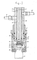
- Fig. 1 shows in axial section a sealing head of a device according to the invention;
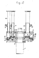
- Fig. 2 shows in axial section the control device according to the invention; and
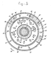
- Fig. 3 shows a cross section along the line III-III in fig. 2.
- The device comprises a number of sealing heads, one of which is shown in fig. 1, and which are mounted, standing upright, at equal angular intervals in a circle, in a manner not illustrated in greater detail, on the vertical central column 1 (see fig. 2).
- Each sealing head has a relatively thick-walled length of tubing 2, which at the top end, for an up and dowm movement, is guided in a curved track (not shown), and within which a
rod 4 provided with acentral channel 3 can slide up and down. Disposed on therod 4 at the bottom end is asuction head 5, so that by connecting thechannel 3, in a manner not further illustrated, to a vacuum source, a closing cap 6 for a container can be sucked fast on thesuction cap 5, while therod 4 is in the bottom position not shown, and if therod 4 is then raised to the position shown, this cap 6 can be taken inside thespace 7 of the sealing head. - This
space 7 is enclosed by asealing sleeve 8 which is connected to a slide piece 8ʹ which is under a downward-directed spring pressure (not shown), and which can slide along the tube 2, permitting thesealing sleeve 8 to move up and down between a bottom position which is not shown and the top position which is shown. In this top position the sealing sleeve encloses the top of the container 9, while thesealing ring 10 disposed at the end of the sealing sleeve engages in sealing fashion with the container 9, so that thespace 7 is sealed off relative to the environment. - Formed between the length of tubing 2 and the
rod 3 is anannular channel 11, which is connected at one end to aconnection piece 12 which can be connected to at least one vacuum source, and at the other end opens into a set ofradial channels 13 which in the highest position of thesealing sleeve 8 are connected to thetop part 14 of thespace 7, so that when theconnection 12 is open to the vacuum source a vacuum is created in the container 9. When no container 9 is accommodated in a sealing head, thesealing sleeve 8 belonging to it will remain in the lowest position, which means that the connection between thechannels 13 and thepart 14 is closed through the fact that the bottom inside edge of the slide piece 8ʹ has engaged with the sealing ring 8ʺ. - Formed through the wall of the length of tubing 2 is an
axial channel 15, which at its one end opens into a connection piece 15ʹ which can be connected to a source for a pressurized chemically inert gas, for example nitrogen, and at the other end merges into anozzle 16 which opens into thespace 7, in such a way that when the said gas flows through thechannel 15, a gas jet is blown into the container 9, being directed in the direction of the arrow A obliquely towards the container 9. - Provision is also made for a
locking mechanism 17 which can retain the cap 6 when thespace 7 is connected to the vacuum source. When the successive steps of creating a vacuum inside a container 9 and blowing a gas into the container through anozzle 16 have been completed, the container 9 is finally closed off by moving therod 4 downwards, thereby causing the closing cap 6 to be pressed into the filling opening of the container 9, thelocking mechanism 17 then being pressed away. - As shown in fig. 2, the control mechanism of the device comprises an essentially closed housing which is formed by a
sleeve 18 which is mounted by means of rolling bearings so that it rotates about the column 1, atop disc 19 fixed to this sleeve, aperipheral wall 20, and an inner 21 and an outerannular disc 22, which are separated from each other by apartition wall 23, by means of which the inside of the closed housing is also divided into twoannular chambers annular chamber 25 is connected by means of the connectingpiece 26 having themeasuring point 27 to a source of a chemically inert compressed gas, for example nitrogen, while the innerannular chamber 24 is connected by means of the connectingpiece 28 having themeasuring point 29 to a first vacuum source. Passed through the innerannular chamber 25 is a length oftubing 30, which at its top end is connected to the connectingpiece 31 withmeasuring point 32, which is connected to a second vacuum source. At the bottom end the length oftubing 30 is accommodated in an opening in the innerannular disc 21. - At their bottom faces the
rings rings 21, 21ʹ and 22, 22ʹ respectively by one single ring made of a plastic material e.g. Deldrin - Provided in the
inner disc 21 are a number ofopenings tubing 30 is accommodated in the opening 35. - Drilled in the
outer disc 22 are a number ofopenings 36, 36ʹ; 37, 37ʹ; 38 of which theopenings 36 and 36ʹ open into an oblong opening 36ʺ which is disposed in the Teflon layer 22ʹ, theopenings 37 and 37ʹ open into an oblong opening 37ʺ disposed in the Teflon layer 22ʹ, and theopening 38 opens into the oblong opening 38ʹ disposed in the Teflon layer 22ʹ. - A
disc 39 is fixed to the column 1 in such a way that the top faces of this disc rest in sealing fashion against the annular Teflon layers 21ʹ and 22ʹ. Disposed in thisdisc 39 are a number ofopenings 40 .....49 lying at equal angular distance from each other, and each being connected by means of pipes (not shown) to the connecting piece 15ʹ of a respective sealing head. Provision is also made in thedisc 39 for a number ofopenings 50.....59 laying on an inner circle at equal angular distances from each other, and each being connected by means of a pipe (not shown) to the connectingpiece 12 of a respective sealing head, while the pairs ofopenings - Whenever now the device is in operation and the column 1 - and consequently the disc 39 - is rotated in the direction of the arrow B, of for example the pair of
openings opening 33, 33ʹ, as a result of which theconnection 12 of the particular sealing head and thereby thespace 7 thereof is connected to the first vacuum source, so that a vacuum will be created in the container 9. The opening 40 will subsequently coincide with the opening 36ʺ, as shown in fig. 3 for theopening 41, as a result of which the connection 15ʹ of the sealing head is connected to the source of a compressed gas, so that a gas jet A will be blown out of thenozzle 16 into the container 9 while, since theopening 50 has reached the position indicated by 51, the connection to the vacuum source is interrupted. On further rotation of thedisc 39, the opening 50 will, however, be brought to coincide with the oblong opening 34ʹ, again creating a vacuum in the container 9, while the connection to the source of a compressed gas is broken, due to the fact that the opening 40 will have reached the position indicated by 42. This opening 40 will subsequently coincide with the oblong opening 37ʺ, again causing a gas jet to flow out of thenozzle 16, while the connection with the vacuum source is interrupted again, due to the fact that therelevant opening 50 has reached the position indicated by 54. Since thereafter thisopening 50 will reach the position indicated by 55, a connection via the length oftubing 30 between the second vacuum source and thespace 7 is formed, thereby creating a final vacuum in the container 9. Immediately after that, the closing cap 6 is pressed into the filling opening of the container by means of therod 4, following which the container 9 is ready. - Since during the creation of the final vacuum a vacuum is also created in the
space 7, it is necessary to release this vacuum in thespace 7, otherwise the sealingsleeve 8 cannot be separated from the container to release the container 9. This vacuum is released through the fact that on a further rotation of thedisc 39 the opening 40 finally coincides with the oblong opening 38ʹ, thereby again connecting thespace 7 to the source of a compressed gas. - Fig. 3 also shows the
openings housing - In the device shown in the figures there are provided six pairs of
openings disc 39 what means that the said device is designed for having ten sealing heads, of which one is shown in figure 1. However it will be understood that devices according to the invention could have also less or more than ten sealing heads.
Claims (6)
1. Process for reducing the quantity of oxygen in the space above the filling in a container before closing of the container, in which a vacuum is formed in said space, then a compressed gas which is inert for the contents of the container is blowin into the container and again a vacuum is formed in said space, these steps being repeated if necessary, characterized in that the compressed gas is blown into the container in a direction running obliquely to the verical axis of symmetry of the container.
2. Process according to claim 1, characterized in that as a last step a final vacuum is created in the space of which the depth differs from the depth of the previous vacuums.
3. Device for carrying out the process according to the preceding claims, comprising a number of sealing heads mounted in the form of a caroussel on a vertical central column which is driven so that it rotates, each of said heads being able to engage in sealing fashion the top of a container provided with a filling opening, so that the filling opening comes to be situated in a space within the sealing head sealed off from the outside air, it being possible to place said space in connection with a source of vaccum and operable valve means for alternately putting into communication said space with a vacuum source and a source of a chemical inert gas, characterized in that a nozzle which can be placed in connection with said source of a chemically inert gas opens into the said space so that it is possible to produce a jet of the said gas flowing out of said nozzle and directed towards the filling opening of a container in a direction extending obliquely to the vertical axis of said container, and said device further comprises a fixed, essentially enclosed housing within which are formed, coaxially with the central column, an inner chamber and an outer, essentially cylindrical chamber enclosing it, one of these chambers being connected to the vacuum source and the other chamber to the source of a chemically inert gas, while in one head face of each chamber provision is made for a number of openings at specific angular distances from each other and disposed on an inner and an outer circle respectively, while fixed on the central rotating column is a disc which rests in sealing fashion against said head faces, and in which two series of openings with equal angular distances from each other are formed on an inner and outer circle respectively, while the radii of these inner and outer circles are virtually equal to those of the first-mentioned inner and outer circle and the openings of the inner series and the openings of the outer series are each individually connected to the said space in a sealing head and the nozzle opening therein respectively.
4. Device according to claim 3, characterized in that provision is made for a length of tubing which rungs in the axial direction through the chamber connected to the vacuum source and which at the said head face of said chamber connects to an opening provided therein, and whose other end is passed through the opposite head face of said chamber and connected to a second vacuum source.
5. Device according to claims 4 or 5, characterized in that the openings in the said head faces of the chambers, at least the part facing the disc, are in the shape of a circular arc-type groove.
6. Device according to claims 4-5, characterized in that the sealing heads are each provided with a suction head to be connected to a vacuum source for taking into the said space a closing cap or cover for the container, a catch mechanism being provided in each sealing head to retain the closing cap.
Applications Claiming Priority (2)
| Application Number | Priority Date | Filing Date | Title |
|---|---|---|---|
| NL8603176A NL8603176A (en) | 1986-12-12 | 1986-12-12 | METHOD AND APPARATUS FOR REDUCING THE AMOUNT OF OXYGEN IN THE SPACE ABOVE THE FILL WITHIN A CONTAINER |
| NL8603176 | 1986-12-12 |
Publications (1)
| Publication Number | Publication Date |
|---|---|
| EP0272736A1 true EP0272736A1 (en) | 1988-06-29 |
Family
ID=19848996
Family Applications (1)
| Application Number | Title | Priority Date | Filing Date |
|---|---|---|---|
| EP87202418A Withdrawn EP0272736A1 (en) | 1986-12-12 | 1987-12-04 | Device for reducing the quantity of oxygen in the space above the filling in a container |
Country Status (3)
| Country | Link |
|---|---|
| US (1) | US4848419A (en) |
| EP (1) | EP0272736A1 (en) |
| NL (1) | NL8603176A (en) |
Cited By (6)
| Publication number | Priority date | Publication date | Assignee | Title |
|---|---|---|---|---|
| EP0622301A1 (en) * | 1993-04-29 | 1994-11-02 | Rudolf Christoph Bilz | Evacuation apparatus |
| WO2008077446A1 (en) * | 2006-12-23 | 2008-07-03 | Khs Ag | Method for closing receptacles, and closing machine |
| ITBO20110260A1 (en) * | 2011-05-11 | 2012-11-12 | Pietro Dovesi | CAPPING AND SUCTION DEVICE |
| WO2019194810A1 (en) * | 2018-04-05 | 2019-10-10 | Norik Kagramanyan | Apparatuses and methods for container content preservation |
| US10773872B2 (en) | 2016-10-06 | 2020-09-15 | Norik Kagramanyan | Apparatuses and methods for container content preservation |
| US10906791B2 (en) | 2016-10-06 | 2021-02-02 | Norik Kagramanyan | Apparatuses and methods for container content preservation |
Families Citing this family (27)
| Publication number | Priority date | Publication date | Assignee | Title |
|---|---|---|---|---|
| US4959960A (en) * | 1988-10-17 | 1990-10-02 | Automotive Products Plc | Method and apparatus for prefilling hydraulic control apparatus |
| US5201165A (en) * | 1990-10-05 | 1993-04-13 | International Paper Company | Gas displacement device for packaging food and non-food products |
| US5085035A (en) * | 1990-10-05 | 1992-02-04 | International Paper Company | Gas displacement device for packaging food and non-food products |
| US5303835A (en) * | 1992-06-24 | 1994-04-19 | Habley Medical Technology Corporation | Lyophilization cap and method |
| US5419096A (en) * | 1993-07-28 | 1995-05-30 | World Class Packaging Systems, Inc. | Packaging method and apparatus for packaging large meat products in a desired gaseous atmosphere |
| DE4429594A1 (en) * | 1994-08-20 | 1996-02-22 | Khs Masch & Anlagenbau Ag | Process for filling a liquid product into bottles or the like |
| DE19708864A1 (en) * | 1997-03-05 | 1998-09-10 | Bosch Gmbh Robert | Evacuation and sealing device for small containers with sealing plugs |
| DE19716846C1 (en) * | 1997-04-22 | 1998-11-19 | Bosch Gmbh Robert | Evacuation and closing device |
| TR200103412T2 (en) * | 1998-06-29 | 2002-06-21 | Astrapak Limited | Valve and packing aseptic package system |
| US6079461A (en) * | 1998-08-17 | 2000-06-27 | The Heil Co. | Use of inert gas in transfer of comminuted product to tank |
| GB0102386D0 (en) * | 2001-01-31 | 2001-03-14 | Weston Medical Ltd | Method for filling needless injector capsules |
| US7040075B2 (en) * | 2001-08-08 | 2006-05-09 | The Clorox Company | Nitrogen cap chute end |
| ITTO20030229A1 (en) * | 2003-03-27 | 2004-09-28 | Arol Spa | CAPSULATING HEAD FOR THE VACUUM APPLICATION OF CAPSULES |
| US7219480B2 (en) * | 2003-08-06 | 2007-05-22 | Alcoa Closure Systems International, Inc. | Capping and nitrogen dosing apparatus |
| US20070062162A1 (en) * | 2005-09-19 | 2007-03-22 | Martin Lehmann | Method and apparatus for cleaning containers to be sealed and containing a filler from oxygen gas |
| DE102006061498A1 (en) * | 2006-12-23 | 2008-07-03 | Khs Ag | Container e.g. bottle, closing method, involves accommodating container in inert gas area or partial area, during closing of container in area of container mouth, where inert gas of inert gas atmosphere is carbon dioxide or nitrogen |
| DE102007041685A1 (en) * | 2007-09-01 | 2009-03-05 | Krones Ag | Device for distributing a medium to containers |
| TWI472459B (en) | 2008-05-19 | 2015-02-11 | Melrose David | Head space modification method for removing vacuum pressure and device thereof |
| FR2933380B1 (en) * | 2008-07-01 | 2013-01-18 | Airlessystems | METHOD FOR CONDITIONING FLUID PRODUCT IN A DISPENSER |
| BR112012011655A2 (en) * | 2009-11-17 | 2016-07-05 | Amcor Rigid Plastics Usa Inc | pressurized closing device |
| US10266293B1 (en) * | 2014-09-15 | 2019-04-23 | Automated Systems of Tacoma LLC | Method and system for vacuum stoppering of fluid containers |
| RU2590995C1 (en) * | 2015-04-24 | 2016-07-10 | Общество с ограниченной ответственностью "Эрмайнс" (ООО "Эрмайнс") | Device for degassing and sealing of vacuum tubes |
| EP3472052A4 (en) * | 2016-06-16 | 2020-01-22 | Muffin Incorporated | Vial filling system with localized clean zone |
| BR112020000634B1 (en) * | 2017-07-11 | 2024-03-05 | Becton Dickinson France | DEVICE, SYSTEM AND METHOD FOR VACUUM LOCKING A MEDICINAL CONTAINER |
| JP6921297B2 (en) * | 2017-07-11 | 2021-08-18 | ベクトン ディキンソン フランス | Device for vacuuming and closing vents in medical containers |
| RU2705818C1 (en) * | 2018-05-30 | 2019-11-12 | Акционерное общество "КВАРЦ" | Vacuum chamber |
| CN114538345B (en) * | 2022-04-12 | 2022-09-27 | 河北橡一医药科技股份有限公司 | Can improve medical plastic-aluminum lid compression fittings of leakproofness |
Citations (6)
| Publication number | Priority date | Publication date | Assignee | Title |
|---|---|---|---|---|
| NL79806C (en) * | 1900-01-01 | |||
| US2017766A (en) * | 1928-10-10 | 1935-10-15 | Anchor Cap & Closure Corp | Sealing machine and method |
| US2656963A (en) * | 1947-09-16 | 1953-10-27 | Fmc Corp | Filling machine |
| GB910584A (en) * | 1960-01-12 | 1962-11-14 | R W Barraclough Ltd | Improvements in or relating to apparatus for evacuating and sealing containers |
| FR1426235A (en) * | 1964-12-03 | 1966-01-28 | Continental Can Co | Filter capping head |
| FR2104100A5 (en) * | 1970-08-07 | 1972-04-14 | Unilever Nv |
Family Cites Families (9)
| Publication number | Priority date | Publication date | Assignee | Title |
|---|---|---|---|---|
| US1591932A (en) * | 1924-01-11 | 1926-07-06 | American Can Co | Method and apparatus for replacing air in filled containers with inert gas |
| US3350839A (en) * | 1963-07-24 | 1967-11-07 | Kenneth B Ray | Apparatus for packaging fruit juices and similar products |
| US3951186A (en) * | 1974-05-17 | 1976-04-20 | Fmc Corporation | Gas flushing system for beverage filler |
| JPS548078A (en) * | 1977-06-17 | 1979-01-22 | Takeda Chemical Industries Ltd | Device for fitting plug in vial to vacuum |
| US4407340A (en) * | 1980-12-18 | 1983-10-04 | Reynolds Metals Company | Container pressurization system |
| US4489767A (en) * | 1981-09-08 | 1984-12-25 | Toyo Seikan Kaisha, Ltd. | Apparatus for dropping liquefied gases |
| DE3431107C2 (en) * | 1984-08-24 | 1987-04-30 | Krones Ag Hermann Kronseder Maschinenfabrik, 8402 Neutraubling | Method and device for filling bottles or the like. |
| US4662154A (en) * | 1984-10-12 | 1987-05-05 | Continental Can Company, Inc. | Liquid inert gas dispenser and control |
| DE3439736A1 (en) * | 1984-10-31 | 1986-04-30 | Krones Ag Hermann Kronseder Maschinenfabrik, 8402 Neutraubling | METHOD AND DEVICE FOR FILLING A LIQUID IN BOTTLES OR THE LIKE. |
-
1986
- 1986-12-12 NL NL8603176A patent/NL8603176A/en not_active Application Discontinuation
-
1987
- 1987-12-04 EP EP87202418A patent/EP0272736A1/en not_active Withdrawn
- 1987-12-09 US US07/130,419 patent/US4848419A/en not_active Expired - Fee Related
Patent Citations (6)
| Publication number | Priority date | Publication date | Assignee | Title |
|---|---|---|---|---|
| NL79806C (en) * | 1900-01-01 | |||
| US2017766A (en) * | 1928-10-10 | 1935-10-15 | Anchor Cap & Closure Corp | Sealing machine and method |
| US2656963A (en) * | 1947-09-16 | 1953-10-27 | Fmc Corp | Filling machine |
| GB910584A (en) * | 1960-01-12 | 1962-11-14 | R W Barraclough Ltd | Improvements in or relating to apparatus for evacuating and sealing containers |
| FR1426235A (en) * | 1964-12-03 | 1966-01-28 | Continental Can Co | Filter capping head |
| FR2104100A5 (en) * | 1970-08-07 | 1972-04-14 | Unilever Nv |
Cited By (7)
| Publication number | Priority date | Publication date | Assignee | Title |
|---|---|---|---|---|
| EP0622301A1 (en) * | 1993-04-29 | 1994-11-02 | Rudolf Christoph Bilz | Evacuation apparatus |
| WO2008077446A1 (en) * | 2006-12-23 | 2008-07-03 | Khs Ag | Method for closing receptacles, and closing machine |
| US9957144B2 (en) | 2006-12-23 | 2018-05-01 | Khs Gmbh | Method for capping or closing containers and capping or closing machine |
| ITBO20110260A1 (en) * | 2011-05-11 | 2012-11-12 | Pietro Dovesi | CAPPING AND SUCTION DEVICE |
| US10773872B2 (en) | 2016-10-06 | 2020-09-15 | Norik Kagramanyan | Apparatuses and methods for container content preservation |
| US10906791B2 (en) | 2016-10-06 | 2021-02-02 | Norik Kagramanyan | Apparatuses and methods for container content preservation |
| WO2019194810A1 (en) * | 2018-04-05 | 2019-10-10 | Norik Kagramanyan | Apparatuses and methods for container content preservation |
Also Published As
| Publication number | Publication date |
|---|---|
| NL8603176A (en) | 1988-07-01 |
| US4848419A (en) | 1989-07-18 |
Similar Documents
| Publication | Publication Date | Title |
|---|---|---|
| EP0272736A1 (en) | Device for reducing the quantity of oxygen in the space above the filling in a container | |
| US4059108A (en) | Process for pheresis procedure and disposable pheresis bowl therefor | |
| US4204537A (en) | Process for pheresis procedure and disposable plasma | |
| US3035886A (en) | Method of sterilizing | |
| JPH01124502A (en) | Powder filler | |
| CA2398921C (en) | Process of bulk filling | |
| US3339595A (en) | Apparatus for transferring measured quantities of pulverulent material | |
| CN111787989B (en) | Apparatus and method for degassing and aerating containers | |
| FI66252C (en) | ANORDINATION AND FARING EQUIPMENT OEVERFOERING AV MYCKET SMAO PULVERMAENGDER | |
| US3624982A (en) | Vacuum packing apparatus | |
| JPH0662121B2 (en) | Equipment for filling substances in containers | |
| US6453953B1 (en) | Flowback method in a filling machine and filling machine for carrying out said method | |
| US3321887A (en) | Method and apparatus for adding liquid fill to containers having solids therein | |
| US6705062B1 (en) | Machine for filling and sealing containers | |
| CN112373789B (en) | Production equipment for producing multilayer protective gas food packaging bags | |
| JP3351445B2 (en) | Capping device | |
| ES2217758T3 (en) | METHOD, APPLIANCE AND ASSEMBLY FOR FILLING OF CONTAINERS. | |
| JP3351446B2 (en) | Tapping system | |
| JPH0775672A (en) | Syringe barrel body for drug container and syringe | |
| EP1484279B1 (en) | Carousel filling machine | |
| JP2023506393A5 (en) | ||
| JPS5984790A (en) | Liquid filling nozzle device | |
| JPS6388405A (en) | Device for weighing and distributing liquefied product | |
| US5470394A (en) | Method and apparatus for treating and cleaning plates by means of a central reactor | |
| CN209684043U (en) | A kind of automatic pressing device that sucking preparation is filling |
Legal Events
| Date | Code | Title | Description |
|---|---|---|---|
| PUAI | Public reference made under article 153(3) epc to a published international application that has entered the european phase |
Free format text: ORIGINAL CODE: 0009012 |
|
| AK | Designated contracting states |
Kind code of ref document: A1 Designated state(s): DE FR GB IT NL |
|
| 17P | Request for examination filed |
Effective date: 19881011 |
|
| 17Q | First examination report despatched |
Effective date: 19900531 |
|
| STAA | Information on the status of an ep patent application or granted ep patent |
Free format text: STATUS: THE APPLICATION IS DEEMED TO BE WITHDRAWN |
|
| 18D | Application deemed to be withdrawn |
Effective date: 19910604 |
|
| RIN1 | Information on inventor provided before grant (corrected) |
Inventor name: DAMEN, FRANCISCUS ANTONIUS |