EP0277823A1 - Ultraschallschneidvorrichtung - Google Patents
Ultraschallschneidvorrichtung Download PDFInfo
- Publication number
- EP0277823A1 EP0277823A1 EP88300903A EP88300903A EP0277823A1 EP 0277823 A1 EP0277823 A1 EP 0277823A1 EP 88300903 A EP88300903 A EP 88300903A EP 88300903 A EP88300903 A EP 88300903A EP 0277823 A1 EP0277823 A1 EP 0277823A1
- Authority
- EP
- European Patent Office
- Prior art keywords
- flexible vibrator
- tool
- vibrator
- flexible
- vibration
- Prior art date
- Legal status (The legal status is an assumption and is not a legal conclusion. Google has not performed a legal analysis and makes no representation as to the accuracy of the status listed.)
- Granted
Links
- 239000000126 substance Substances 0.000 claims abstract description 14
- 229910052751 metal Inorganic materials 0.000 claims abstract description 12
- 239000002184 metal Substances 0.000 claims abstract description 12
- 238000001514 detection method Methods 0.000 claims description 14
- 238000004804 winding Methods 0.000 claims description 14
- 230000010287 polarization Effects 0.000 claims description 8
- 238000009413 insulation Methods 0.000 claims description 6
- 238000006073 displacement reaction Methods 0.000 description 10
- 230000004048 modification Effects 0.000 description 10
- 238000012986 modification Methods 0.000 description 10
- 230000000694 effects Effects 0.000 description 9
- 230000003247 decreasing effect Effects 0.000 description 6
- 238000002474 experimental method Methods 0.000 description 5
- 230000002159 abnormal effect Effects 0.000 description 3
- BQCADISMDOOEFD-UHFFFAOYSA-N Silver Chemical compound [Ag] BQCADISMDOOEFD-UHFFFAOYSA-N 0.000 description 2
- 229910000831 Steel Inorganic materials 0.000 description 2
- 238000005219 brazing Methods 0.000 description 2
- 238000010586 diagram Methods 0.000 description 2
- 230000005284 excitation Effects 0.000 description 2
- 229910052709 silver Inorganic materials 0.000 description 2
- 239000004332 silver Substances 0.000 description 2
- 239000010959 steel Substances 0.000 description 2
- 238000005452 bending Methods 0.000 description 1
- 238000006243 chemical reaction Methods 0.000 description 1
- 239000002131 composite material Substances 0.000 description 1
- 230000005484 gravity Effects 0.000 description 1
- 239000007788 liquid Substances 0.000 description 1
- 238000000034 method Methods 0.000 description 1
Images


Classifications
-
- B—PERFORMING OPERATIONS; TRANSPORTING
- B23—MACHINE TOOLS; METAL-WORKING NOT OTHERWISE PROVIDED FOR
- B23H—WORKING OF METAL BY THE ACTION OF A HIGH CONCENTRATION OF ELECTRIC CURRENT ON A WORKPIECE USING AN ELECTRODE WHICH TAKES THE PLACE OF A TOOL; SUCH WORKING COMBINED WITH OTHER FORMS OF WORKING OF METAL
- B23H7/00—Processes or apparatus applicable to both electrical discharge machining and electrochemical machining
- B23H7/38—Influencing metal working by using specially adapted means not directly involved in the removal of metal, e.g. ultrasonic waves, magnetic fields or laser irradiation
-
- B—PERFORMING OPERATIONS; TRANSPORTING
- B23—MACHINE TOOLS; METAL-WORKING NOT OTHERWISE PROVIDED FOR
- B23B—TURNING; BORING
- B23B29/00—Holders for non-rotary cutting tools; Boring bars or boring heads; Accessories for tool holders
- B23B29/04—Tool holders for a single cutting tool
- B23B29/12—Special arrangements on tool holders
- B23B29/125—Vibratory toolholders
-
- B—PERFORMING OPERATIONS; TRANSPORTING
- B23—MACHINE TOOLS; METAL-WORKING NOT OTHERWISE PROVIDED FOR
- B23B—TURNING; BORING
- B23B1/00—Methods for turning or working essentially requiring the use of turning-machines; Use of auxiliary equipment in connection with such methods
-
- Y—GENERAL TAGGING OF NEW TECHNOLOGICAL DEVELOPMENTS; GENERAL TAGGING OF CROSS-SECTIONAL TECHNOLOGIES SPANNING OVER SEVERAL SECTIONS OF THE IPC; TECHNICAL SUBJECTS COVERED BY FORMER USPC CROSS-REFERENCE ART COLLECTIONS [XRACs] AND DIGESTS
- Y10—TECHNICAL SUBJECTS COVERED BY FORMER USPC
- Y10S—TECHNICAL SUBJECTS COVERED BY FORMER USPC CROSS-REFERENCE ART COLLECTIONS [XRACs] AND DIGESTS
- Y10S82/00—Turning
- Y10S82/904—Vibrating method or tool
-
- Y—GENERAL TAGGING OF NEW TECHNOLOGICAL DEVELOPMENTS; GENERAL TAGGING OF CROSS-SECTIONAL TECHNOLOGIES SPANNING OVER SEVERAL SECTIONS OF THE IPC; TECHNICAL SUBJECTS COVERED BY FORMER USPC CROSS-REFERENCE ART COLLECTIONS [XRACs] AND DIGESTS
- Y10—TECHNICAL SUBJECTS COVERED BY FORMER USPC
- Y10T—TECHNICAL SUBJECTS COVERED BY FORMER US CLASSIFICATION
- Y10T82/00—Turning
- Y10T82/25—Lathe
- Y10T82/2585—Tool rest
- Y10T82/2589—Quick release tool or holder clamp
Definitions
- the present invention relates to ultrasonic working devices utilizing ultrasonic vibration, particularly ultrasonic vibration cutting devices such as a lathe, a shaper, a planer, and more specifically to a untrasonic vibration cutting device utilizing flexible vibration as ultrasonic vibration.
- Vibration cutting devices utilizing ultrasonic vibration are known well in the prior art. For example, if a tool shank in a lathe is vibrated in flexible vibration and a tool attached to top end of the tool shank is subjected to ultrasonic vibration in tangential direction of a work for cutting thereby working is performed, cutting resistance is significantly decreased and the working accuracy is improved thus large effects can be obtained.
- FIG. 1 shows such a cutting device as an example in the prior art.
- a pushing plate 2 On a tool post 1, a pushing plate 2, a tightening bolt 3, a tightening jig 4 and a tool shank (tool holder) 5 to perform bending (flexible) vibration by these are supported.
- the tightening jig 4 is set to be positioned to node portion of the tool shank 5.
- a cutting tool 7 as tool facing a work 6 is fixed to one top end of the tool shank 5.
- a vertical vibrator 8 and an amplitude enlarging horn 9 are contacted at other end side of the tool shank 5, and positioned to loop portion of vibration mode (shown by dash-and-dot line) of the tool shank 5.
- the vertical vibrator 8 is driven by a ultrasonic oscillator (not shown)
- the tool shank 5 is vibrated as in dash-and-dot line shown and top end of the cutting tool 7 is subjected to ultrasonic vibration in the cutting direction thereby the vibration cutting effects as above described can be exhibited.
- the cutting speed of the work 6 is made v
- vibration frequency of the cutting tool 7 vibrating is made f
- amplitude is made a
- the vertical vibrator 8 as generating source of ultrasonic vibration can be mounted on position remote from the cutting tool 7, the device can be easily installed to a general-purpose lathe and therefore is sdvantageous.
- a first object of the invention is to provide an ultrasonic vibration cutting device having structure not to deteriorate the workability.
- a second object of the invention is to provide an ultrasonic vibration cutting device where the device can be made compact.
- a third object of the invention is to provide an ultrasonic vibration cutting device where the structure can be simplified.
- a fourth object of the invention is to provide an ultrasonic vibration cutting device where accurate mounting of a cutting tool can be easily performed.
- a fifth object of the invention is to provide an ultrasonic vibration cutting device where enlarging ratio of vibration amplitude can be increased.
- a sixth object of the invention is to provide an ultrasonic vibration cutting device where vibration loss can be decreased.
- a seventh object of the invention is to provide an ultrasonic vibration cutting device where generation of the harmful and abnormal vibration can be prevented.
- FIGS. 3 through 11 A first embodiment of the invention will be described referring to FIGS. 3 through 11.
- a flexible vibrator 10 is installed, and enclosed and supported, for example, in a holder 11 formed upward in U-like form.
- Such flexible vibrator 10 is equivalent, for example, to that disclosed in JP A 62-114478 by the present applicant.
- a ring-shaped electrostrictive element body 12 polarized in thickness direction is installed.
- electrodes 14, 15 are formed in dividing in two about an insulation portion 13, and on other surface thereof, a common electrode 16 is formed as a whole electrode thus an electrostrictive element 17 is constituted by these.
- two electrostrictive elements 17 in such constitution are prepared and the insulation portions 13 are registered, and two electrode plates 18, 19 in U-like form as shown in FIG.
- the electrodes 14, 15 are opposed and an insulation cylinder 20 is inserted in center portion.
- an output end portion 21 is made thin, and a metal substance 23 with an exponential step portion 22 to form a horn for vibration amplitude enlarging is contacted.
- a common electrode plate 24 is contacted and a metal substance 25 is contacted with the common electrode plate 24.
- These members are fixed integrally by a bolt as tightening tool. That is, the metal substance 25 is provided with a hole 27 for inserting the bolt 26, and the metal substance 23 is provided with a threaded portion 28 for threaded engagement of the bolt 26.
- a drive control circuit as hereinafter described is connected to such flexible vibrator 10 through the electrodes 14, 15, the common electrode 16, the electrode plates 18, 19 and the common electrode plate 24, and the flexible vibrator 10 is excited and driven by the drive control circuit.
- the drive power source which can be controlled in independent phases from each other is connected to the electrode plates 18, 19 and the common electrode plate 24, and the drive frequency is adjusted to the axial resonance frequency.
- the phase difference is made zero, same phase parallel drive is performed, and the output end portion 21 becomes the axial resonance vibration and is vibrated in similar vibration mode to that of the vertical vibrator.
- phase of drive voltage to be applied to other electrode 19 with respect to one electrode 18 is inverted, i.e., if voltage of reverse phase is applied, the output end portion 21 is bent in perpendicular direction to the axis and in dividing direction of the electrostrictive element 17 (i.e., in vertical direction shown in FIG. 6), and performs resonance vibration.
- each of the electrodes 14, 15 may be supplied with reverse polarization directions from each other in the thicknes direction. In this case, voltage of the same phase is applied to the two electrode plates 18, 19, thereby flexible vibration is generated in the output end portion 21.
- the electrostrictive element 17 may be separated and of semicircular ring-shaped element structure; and the polarization direction may be the same direction or reverse direction.
- the flexible vibrator 10 in such structure is schematically shown in FIGS. 3 through 5.
- characteristics A in FIG. 4(b) such flexible vibrator 10 is constituted to perform flexible resonance in one wave length on the axial line.
- the flexible vibrator 10 is provided with conical recesses 29 formed on four node positions N1, N2, N1 ⁇ , N2 ⁇ at both lateral sides.
- the flexible vibrator 10 from the output end portion 21 to the first node positions N1, N1 ⁇ is made thin including the exponential step portion 22 so that the flexible vibration displacement at the output end portion 21 is enlarged.
- the embodiment is characterized in that the cutting tool 33 as tool to perform cutting of the work 32 is installed directly to the output end portion 21 of the flexible vibrator 10.
- the structure is quite simple and the vertical vibrator as in the ultrasonic vibration cutting device in the prior art becomes unnecessary. Thereby the structure is simplified and the workability is improved. Further, the vibration amplitude enlarging ratio is increased, and the total length may be small in comparison to the vibration system in the prior art thereby the device is made small and compact.
- FIG. 4(c) shows instantaneous vibration displacement distribution viewing from side of the flexible vibrator 10 in amount and direction of each arrow B, and the distribution in FIG. 4(c) corresponds to characteristics A of the flexible vibration displacement distribution on the axial direction shown in FIG. 4(b). L designates the loop position. As understood also from each arrow B in FIG.
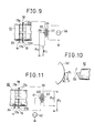
- the drive system of the flexible vibrator 10 may be constituted as shown in FIG. 9.
- direction of residual polarization is shown by arrow in each of the electrostrictive elements 17a, 17b divided in two by the insulation portion 13.
- the electrode plates 18, 19 are connected to both ends of a secondary winding 35 of an output transformer 34.
- a center tap 36 of the secondary winding 35 is grounded through a detection resistor R s .
- a drive power source 38 is connected to both ends of a primary winding 37 of the output transformer 34, and one end of the drive power source 38 is grounded. Also the common electrode plate 24 is grounded.
- the vibration direction of the cutting tool 33 is tangential direction to the work 33, and as described referring to FIG. 2, if the back component force in the axial direction is applied to the cutting tool the vibration cutting effect will be eliminated. Consequently, angle of the axial line of the flexible vibrator 10 may be set so that such back component force is not applied to the cutting tool 33. In order to attain this, for example, such back component force is detected, and the back component force may be made zero (Null) at setting the angle of the axial line of the vibrator.
- the angle setting can be performed, for example, by adjustment of mounting angle of the holder 11 to the machine tool.
- signal voltage E s is generated in the detection resistor R s by piezoelectric phenomenon when stress of the same direction is applied simultaneously to both electrostrictive elements 17a, 17b. Since the extending or contracting direction is reverse in both electrostrictive elements 17a, 17b, the signal voltage E s is not detected to the load in the vibration direction component. On the other hand, if the back component force is applied during the cutting working, the signal voltage E s is generated by receiving the force in the axial direction, thereby it is discriminated whether the back component force exists or not.
- the angle setting of the axial line of the flexible vibrator 10 to the work 32 may be performed. If the detection function of the back component force is not required, the detection resistor R s may be omitted and the center tap 36 of the secondary winding 35 of the output transformer 34 may be directly grounded.
- the drive system shown in FIG. 11 may be used. That is, each of the electrode plates 18, 19 is excited by voltage in the same phase as that of the resonance frequency, and connection position of the drive power source and the detection resistor is changed in comparison to FIG. 9. Both ends of a primary winding 40 of a detection transformer 39 are connected to the electrode plates 18, 19, and a drive power source 42 is connected to a center tap 41 of the primary winding 40 and grounded. On the other hand, the detection resistor R s is connected to both ends of a secondary winding 43, and one end thereof is grounded.
- FIG. 12 shows a modification regarding support position by four points of the flexible vibrator 10. That is, the arrangement position of the electrostrictive element 17 is changed so that the electrostrictive element 17 is not disposed in the position of the conical recess 29 being the support position of the flexible vibrator 10. According to such structure, since the electrostrictive element 17 is disposed out of the support positions by four-point contacting, relative position shifting of the node position due to tightening during the vibrator assembling, i.e., shifting of the positon of the conical recess 29, can be prevented.
- flexible vibrator 10 is not limited to circular cross-section, but may be square cross-section for example.
- the number of the electrostrictive elements 17 to be used is not limited to two, but may be one or three or more.
- the cutting tool 33 is detachably installed to the flexible vibrator 10. That is, the cutting tool 33 is not installed directly to the output end portion 21 of the flexible vibrator 10 but a right-handed male screw thread 50 is formed on an outer circumferential surface thereof.
- the cutting tool 33 is fixed to one end by silver brazing method or the like, and a tool holder 52 with a left-handed male screw thread 51 of the same diameter as that of thr right-handed male screw thread 50 formed on the outer circumferential surface is installed to other end.
- a spanner setter 53 is formed on a part of the outer circumferential surface of the tool holder 52. Further, a tightening ring 56 as connecting tool is installed, and a right-handed female screw thread 54 and a left-handed female screw thread 55 are formed on an inner circumferential surface of the tightening ring 56, and a spanner setter (not shown) is formed on an outer circumferential surface thereof.
- the right-handed female screw thread 54 of the tightening ring 56 is threadedly engaged with the right-handed male screw thread 50 of the flexible vibrator 10, and the left-handed female screw thread 55 is threadedly engaged with the left-handed male screw thread 52 of the tool holder 52, thereby the flexible vibrator 10 and the tool holder 52 are tightened.
- the spanner setter of the tightening ring 56 serves for the tightening
- the spanner setter 53 of the tool holder 52 serves mainly for the angle registering.
- the cutting tool 33 is detachably installed to the flexible vibrator 10. Consequently, if a plurality of tool holders 52 with various cutting tools 33 fixed thereto are provided, the cutting working by sny sort of the cutting tool 33 can be performed only by changing of the tool holder 52 without removing the flexible vibrator 10 from the holder 11. Also when regrinding of the cutting tool 33 is required, the tool holder 52 is detached from the flexible vibrator 10 and can be used for the working easily and rapidly.
- the flexible vibrator 10 is driven so that characteristics of the vibration displacement distribution becomes characteristics A shown in FIG. 13(b) and FIG. 14(b) for example. That is, the edge of the cutting tool 33 is disposed naturally to the loop position, and also the tightening ring 56 is disposed to the loop position L1. Thereby mass of the tightening ring 56 is added to the loop position L1, which contributes to enlarging of the vibration amplitude of the cutting tool 33. Moreover, since the equivalent mass of the 1/2 wave length resonance region is increased in region from the loop position L1 to the edge of the cutting tool 33, both the vibration speed and the vibration inertia of the cutting tool 33 are increased.
- the flexible vibrator 10 is constituted in that the two electrostrictive elements 17 divided in two of diameter 45 mm and thickness 5 mm are assembled between steel substances with large diameter portion of ⁇ 45 mm and small diameter portion of ⁇ 18 mm.
- the tool holder 52 is constituted in that a superhard cutting tool 33 is contacted in silver brazing to an end portion of a steel substance with large diameter portion of ⁇ 18 mm and small diameter portion of ⁇ 10 mm.
- the tightening ring 56 is a hexagon nut where a right-handed female screw thread and a left-handed female screw thread with M18 are machined on an inner circumference of diagonal 22 mm and length 16 mm.
- FIG. 15 shows an embodiment where the tightening ring 56 is of cap nut structure. That is, only when the tightening ring 56 is threadedly engaged with the flexible vibrator 10, an edge portion 52a formed on the tool holder 52 is pressed to the output end portion 21 of the flexible vibrator 10 by a step portion 56a formed on the inner circumferential surface of the tightening ring 56, thereby the flexible vibrator 10 and the tool holder 52 are fixed. According to such structure, connection between the flexible vibrator 10 and the tool holder 52 can be performed more simply and rapidly.
- FIG. 15 shows an embodiment where the tightening ring 56 is of cap nut structure. That is, only when the tightening ring 56 is threadedly engaged with the flexible vibrator 10, an edge portion 52a formed on the tool holder 52 is pressed to the output end portion 21 of the flexible vibrator 10 by a step portion 56a formed on the inner circumferential surface of the tightening ring 56, thereby the flexible vibrator 10 and the tool holder 52 are fixed. According to
- FIG. 16 shows another modification where a slit 57 is provided on each contact portion between the flexible vibrator 10 and the tool holder 52, and a positioning plate 58 as rotation preventing means is inserted in the slit 57, thereby the flexible vibrator 10 and the tool holder 52 are connected.
- tightening between the flexible vibrator 10 and the tool holder 52 is performed in that the tightening ring 56 is threadedly engaged with the right-handed male screw thread 50 of the flexible vibrator 10 and the left-handed male screw thread 51 of the tool holder 52 as shown in FIG. 16, or in the cap nut structure as shown in FIG. 15.
- Also forming position of the slit 57 is previously set to position so that the tool holder 52 is in the correct mounting direction to the flexible vibrator 10. Consequently in such structure, the positioning of the tool holder 52 during tightening becomes unnecessary.
- the cutting tool 33 is not installed directly to side of the output end portion 21 of the flexible vibrator 10, and therefore this point is common to the second embodiment and the third embodiment. Consequently, the same parts and the equivalent parts to those in the first embodiment and the second embodiment are designated by the same reference numerals, and the description shall be omitted.
- the third embodiment is different from the second embodiment in particulars of mounting structure of the tool holder 52 and characteristics of the vibration displacement distribution of the flexible vibrator 10.
- the right-handed male screw thread 50 is formed on the outer circumferential surface and a slit 60 as rotation preventing means is formed on the end surface.
- the left-handed male screw thread 51 with the same diameter as that of the right-handed male screw thread 50 and in different direction is formed on the outer circumferencial surface, and a plate-shaped projection 61 as rotation preventing means to fit to the slit 60 is projected and formed on the end surface.
- the mounting structure of the tool holder 52 may be the cap nut structure as described referring to FIG. 15.
- the vibration displacement distribution is set so that the standing wave of 1.5 wave length is produced from the rear end of the flexible vibrator 10 to the top end of the cutting tool 33, thereby the connection position between the flexible vibrator 10 and the tool holder 52 is disposed to the node position N3.
- This is the countermeasure in view of the fact that the connection point between the flexible vibrator 10 and the tool holder 52 becomes weak in the strength. That is, the connection point between the flexible vibrator 10 and the tool holder 52 is disposed to the node position N3 where strain stress is not theoretically applied, thereby weakness of the connection point in the strength is compensated.
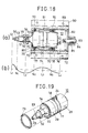
- FIGS. 18 through 22 This embodiment relates to holding structure of the flexible vibrator 10.
- the flexible vibrator 10 to be used is similar to that described in the second embodiment where the cutting tool 33 is detachably installed. Consequently, the same parts and the equivalent parts to those described in the first embodiment and the second embodiment are designated by the same reference numerals, and the description shall be omitted.
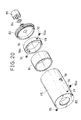
- a ring-shaped body 71 having a setscrew 70 to support the flexible vibrator 10 at the node portion is installed on the outer circumference of the flexible vibrator 10, and is tightened by a housing 72 thereby the flexible vibrator 10 is held. Structure of the flexible vibrator 10, the ring-shaped body 71 and the housing 72 will now be described.
- R step portion 22 as step portion to form a horn portion is formed, and a groove 74 is formed on a surface where the R step portion 22 is formed and an O-ring 73 is inserted along its circumference.
- Structure of the flexible vibrator 10 of the fourth embodiment is different from that described in the second embodiment only in this point.
- the ring-shaped body 71 comprises a cylindrical sleeve 75 with both ends opened, and a ring 76 pushed in the sleeve 75.
- two tapped holes 77 are formed and positioned to the node portion N2 of the vibration of the flexible vibrator 10
- two adjusting holes 78 are formed and positioned to the node portion N3.
- Two tapped holes 79 are formed also at the ring 76 and registered with these adjusting holes 78.
- the setscrews 70 are threadedly engaged with all four tapped holes 77, 79, and top end of each setscrew 70 is locked to the conical recess 29 of the flexible vibrator 10 thereby the flexible vibrator 10 is held in the point contacting.
- a hexagon hole 70a is formed commonly on the head of the setscrew 70.
- a portion of the cutting tool 33 is projected from an opening on one end of the sleeve 75, and a flange 80 at the opening to project the cutting tool 33.
- the flange 80 is positioned so that the flexible vibrator 10 held correctly is pressed through the O-ring 73 made of rubber.
- an insulation cylinder 81 of circular ring form is inserted, in order to protect the sleeve 75 from the plasma effect which may be produced irregularly and instantaneously in the electrostrictive element 17 to which high voltage is applied.
- a cap 82 is tightened by screwing.
- a cable 83 to connect the electrode plates 18, 19 and the common electrode plate 24 to the external circuit is inserted in the cap 82.
- An O-ring 84 is fitted to the cable 83 on outside of the sleeve 75, and is pressed to the cap 82 by a cap nut 85 screwed to the cap 82.
- a groove 76a for inserting the cable 75 is cut on the ring 76 so that connection of the cable 83 to the electrodes 4, 15 and the common electrode 16 is not obstructed.
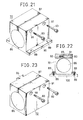
- the housing 72 is of parallelopipedon form, and a cylindrical cavity 86 to hold the sleeve 75 penetrates from one end to other end of the housing, and a split groove 87 is formed so that the cavity 86 communicates with the upper surface.
- a collar 90 having bolt holes 89 for fixing it using bolts 88 to a workbench 100 such as a tool post, a table or the like is formed.
- two inserting holes 91 are formed in horizontal direction on one thick portion, and tightening tapped holes 92 as tapped holes corresponding to these inserting holes 91 are formed in horizontal direction on other thick portion via the split groove 87.
- a bolt 93 with hexagon hole as tightening body is inserted in each inserting hole 91 and threadedly engaged with each tightening tapped hole 92, and the diameter of the cavity 86 is varied delicately by the tightening condition of these bolts 93 with hexagon hole.
- the flexible vibrator 10 is supported by the setscrews 70 at positions of the node portions N2, N3 of the vibration in the point contacting state.
- the ring-shaped body 71 to support the flexible vibrator 10 is inserted within the cavity 86 in the housing 72, and fixed with uniform and strong force by tightening the bolts 93 with hexagon hole. Consequently, the flexible vibrator 10 can be held with high rigidity against the cutting force, and the loss to the vibration can be decreased and other secondary advantages can be produced.
- the flexible vibrator 10 is held within the sleeve 75 in air tightness by the O-ring 73 made of rubber and the O-ring 84. Consequently, the cutting liquid supplied to the cutting tool 33 during cutting can be securely prevented from leaking into the electrostrictive element 17.
- FIG. 23 shows a modification of the housing 72.
- a tail 94 is provided on a side surface and fitted to a devotail groove (not shown) of a tool post, a table or the like thereby the housing 72 can be fixed at any position and can be moved in vertical direction.
Landscapes
- Engineering & Computer Science (AREA)
- Mechanical Engineering (AREA)
- Physics & Mathematics (AREA)
- Optics & Photonics (AREA)
- Chemical & Material Sciences (AREA)
- Chemical Kinetics & Catalysis (AREA)
- Electrochemistry (AREA)
- Apparatuses For Generation Of Mechanical Vibrations (AREA)
- Turning (AREA)
Applications Claiming Priority (6)
| Application Number | Priority Date | Filing Date | Title |
|---|---|---|---|
| JP2404787A JPH0649242B2 (ja) | 1987-02-04 | 1987-02-04 | 超音波振動切削装置 |
| JP24047/87 | 1987-02-04 | ||
| JP116187/87 | 1987-05-13 | ||
| JP62116187A JPS63283801A (ja) | 1987-05-13 | 1987-05-13 | 超音波振動切削装置 |
| JP62124721A JPS63288601A (ja) | 1987-05-20 | 1987-05-20 | 超音波振動切削装置 |
| JP124721/87 | 1987-05-20 |
Publications (2)
| Publication Number | Publication Date |
|---|---|
| EP0277823A1 true EP0277823A1 (de) | 1988-08-10 |
| EP0277823B1 EP0277823B1 (de) | 1991-04-24 |
Family
ID=27284494
Family Applications (1)
| Application Number | Title | Priority Date | Filing Date |
|---|---|---|---|
| EP88300903A Expired - Lifetime EP0277823B1 (de) | 1987-02-04 | 1988-02-03 | Ultraschallschneidvorrichtung |
Country Status (4)
| Country | Link |
|---|---|
| US (1) | US4911044A (de) |
| EP (1) | EP0277823B1 (de) |
| KR (1) | KR910009624B1 (de) |
| DE (1) | DE3862474D1 (de) |
Cited By (8)
| Publication number | Priority date | Publication date | Assignee | Title |
|---|---|---|---|---|
| EP0720890A1 (de) * | 1994-12-16 | 1996-07-10 | HILTI Aktiengesellschaft | Handgerät zur materialabtragenden Bearbeitung von spröden und/oder duktil versagenden Werkstoffen |
| RU2245763C1 (ru) * | 2003-05-12 | 2005-02-10 | Тольяттинский государственный университет | Способ вибрационной обработки тел вращения |
| EP1710034A1 (de) * | 2005-04-06 | 2006-10-11 | HILTI Aktiengesellschaft | Spannvorrichtung für axial harmonisch schwingende Bauteile |
| WO2007130160A1 (en) * | 2006-05-03 | 2007-11-15 | Purdue Research Foundation | Method of producing nanocrystalline chips |
| WO2007130161A1 (en) * | 2006-05-03 | 2007-11-15 | Purdue Research Foundation | Tool holder assembly and method for modulation-assisted machining |
| CN109158622A (zh) * | 2018-10-16 | 2019-01-08 | 东华理工大学 | 一种基于普通车床的纵向超声振动车削装置 |
| EP3530425A1 (de) | 2018-02-27 | 2019-08-28 | Telsonic Holding AG | Schneidwerkzeug für eine ultraschallschneidvorrichtung und ultraschallschneidvorrichtung |
| CN114985556A (zh) * | 2022-06-29 | 2022-09-02 | 中南大学 | 一种金属加工方法以及装置 |
Families Citing this family (24)
| Publication number | Priority date | Publication date | Assignee | Title |
|---|---|---|---|---|
| US5718154A (en) * | 1996-06-27 | 1998-02-17 | Bausch & Lomb, Inc. | Reciprocating tool holder assembly |
| US6404104B1 (en) * | 1997-11-27 | 2002-06-11 | Canon Kabushiki Kaisha | Vibration type actuator and vibration type driving apparatus |
| US6637303B2 (en) * | 1998-08-12 | 2003-10-28 | Toshimichi Moriwaki | Elliptical vibration cutting method and elliptical vibration cutting apparatus |
| US6202521B1 (en) * | 1998-12-14 | 2001-03-20 | Lord Corporation | Method, apparatus and controller for machining non-circular work pieces |
| JP3469516B2 (ja) * | 1999-12-09 | 2003-11-25 | 株式会社アルテクス | 超音波振動切断用ツール及びその製造方法 |
| DE10025352B4 (de) * | 2000-05-23 | 2007-09-20 | Hilti Ag | Werkzeuggerät mit einem Ultraschalladapter |
| JP3806603B2 (ja) | 2001-02-23 | 2006-08-09 | Towa株式会社 | 楕円振動装置及び楕円振動装置の制御方法 |
| US7259496B2 (en) * | 2002-04-08 | 2007-08-21 | University Of North Carolina At Charlotte | Tunable vibratory actuator |
| US20050028657A1 (en) * | 2003-08-04 | 2005-02-10 | Mitro Richard John | Tunable cutting device |
| CN100337776C (zh) * | 2005-12-21 | 2007-09-19 | 杭州电子科技大学 | 弯曲振动车削刀杆节点压块自动调整装置 |
| US8205530B2 (en) * | 2008-10-03 | 2012-06-26 | Subramanian Sundaresa V | Processes for improving tool life and surface finish in high speed machining |
| US8694133B2 (en) | 2009-09-05 | 2014-04-08 | M4 Sciences, Llc | Control systems and methods for machining operations |
| NO335949B1 (no) * | 2010-05-10 | 2015-03-30 | Teeness Asa | Stangformet verktøyholder for innfesting av skjær i knutepunkt |
| DE102011077568B4 (de) * | 2011-06-15 | 2023-12-07 | Dmg Mori Ultrasonic Lasertec Gmbh | Werkzeugmaschine, Werkstückbearbeitungsverfahren |
| TW201350234A (zh) * | 2012-06-06 | 2013-12-16 | Hon Hai Prec Ind Co Ltd | 滾筒加工裝置 |
| CN102806361A (zh) * | 2012-08-31 | 2012-12-05 | 赵显华 | 超声波后置单向振动车削方法 |
| US10245652B2 (en) | 2012-11-05 | 2019-04-02 | M4 Sciences Llc | Rotating tool holder assembly for modulation assisted machining |
| US20140326116A1 (en) * | 2013-05-03 | 2014-11-06 | Tyco Electronics Corporation | Die component for a press device |
| US10589367B2 (en) * | 2014-10-08 | 2020-03-17 | Citizen Watch Co., Ltd. | Machine tool and control device of the machine tool |
| WO2017043499A1 (ja) * | 2015-09-10 | 2017-03-16 | シチズン時計株式会社 | 工作機械の制御装置、工作機械 |
| TWI697380B (zh) * | 2015-09-24 | 2020-07-01 | 日商西鐵城時計股份有限公司 | 工具機的控制裝置以及具備該控制裝置的工具機 |
| US10875138B1 (en) | 2016-08-09 | 2020-12-29 | M4 Sciences Llc | Tool holder assembly for machining system |
| US20190388977A1 (en) * | 2018-06-25 | 2019-12-26 | Hamilton Sundstrand Corporation | Hard turning systems and methods |
| CN115229220B (zh) * | 2022-08-12 | 2025-06-27 | 山东科技大学 | 一种刚度双向可调的可拆卸快刀伺服平台及方法 |
Citations (5)
| Publication number | Priority date | Publication date | Assignee | Title |
|---|---|---|---|---|
| US3739665A (en) * | 1970-04-08 | 1973-06-19 | Rikagaku Kenkyusho | Vibrating cutting method and apparatus |
| US3772538A (en) * | 1973-01-08 | 1973-11-13 | Kane Corp Du | Center bolt type acoustic transducer |
| FR2537899A1 (fr) * | 1982-12-17 | 1984-06-22 | Rouchouze Sa Ets | Dispositif adaptable sur machines-outils telles que tours utilises pour la fabrication des ecrous |
| US4496321A (en) * | 1981-08-24 | 1985-01-29 | Masaru Kumabe | Vibration method for cutting teeth |
| US4567797A (en) * | 1984-01-30 | 1986-02-04 | Folk Donald C | Ultrasonic cutting apparatus and methods |
Family Cites Families (6)
| Publication number | Priority date | Publication date | Assignee | Title |
|---|---|---|---|---|
| US2704333A (en) * | 1951-03-15 | 1955-03-15 | Raytheon Mfg Co | Ultrasonic vibratory devices |
| US2748298A (en) * | 1951-03-15 | 1956-05-29 | Raytheon Mfg Co | Ultrasonic vibratory devices |
| JPS5414784B2 (de) * | 1972-06-23 | 1979-06-09 | ||
| US4071141A (en) * | 1975-12-05 | 1978-01-31 | Lifetime Carbide Co. | Method and product for attaching cutting tips to cutting tools |
| JPS60255301A (ja) * | 1984-05-30 | 1985-12-17 | Taga Denki Kk | 角板形正方共振体共振装置 |
| JPS62114478A (ja) * | 1985-11-11 | 1987-05-26 | Taga Denki Kk | 超音波振動子とその駆動制御方法 |
-
1988
- 1988-02-03 EP EP88300903A patent/EP0277823B1/de not_active Expired - Lifetime
- 1988-02-03 DE DE8888300903T patent/DE3862474D1/de not_active Expired - Fee Related
- 1988-02-04 US US07/152,103 patent/US4911044A/en not_active Expired - Fee Related
- 1988-02-04 KR KR1019880001023A patent/KR910009624B1/ko not_active Expired
Patent Citations (5)
| Publication number | Priority date | Publication date | Assignee | Title |
|---|---|---|---|---|
| US3739665A (en) * | 1970-04-08 | 1973-06-19 | Rikagaku Kenkyusho | Vibrating cutting method and apparatus |
| US3772538A (en) * | 1973-01-08 | 1973-11-13 | Kane Corp Du | Center bolt type acoustic transducer |
| US4496321A (en) * | 1981-08-24 | 1985-01-29 | Masaru Kumabe | Vibration method for cutting teeth |
| FR2537899A1 (fr) * | 1982-12-17 | 1984-06-22 | Rouchouze Sa Ets | Dispositif adaptable sur machines-outils telles que tours utilises pour la fabrication des ecrous |
| US4567797A (en) * | 1984-01-30 | 1986-02-04 | Folk Donald C | Ultrasonic cutting apparatus and methods |
Cited By (12)
| Publication number | Priority date | Publication date | Assignee | Title |
|---|---|---|---|---|
| EP0720890A1 (de) * | 1994-12-16 | 1996-07-10 | HILTI Aktiengesellschaft | Handgerät zur materialabtragenden Bearbeitung von spröden und/oder duktil versagenden Werkstoffen |
| US5733074A (en) * | 1994-12-16 | 1998-03-31 | Hilti Aktiengesellschaft | Manual tool for removing material from brittle and/or non-ductile stock |
| DE4444853B4 (de) * | 1994-12-16 | 2006-09-28 | Hilti Ag | Handgerät zur materialabtragenden Bearbeitung mit elektroakustischem Wandler für die Erzeugung von Ultraschallschwingungen |
| RU2245763C1 (ru) * | 2003-05-12 | 2005-02-10 | Тольяттинский государственный университет | Способ вибрационной обработки тел вращения |
| EP1710034A1 (de) * | 2005-04-06 | 2006-10-11 | HILTI Aktiengesellschaft | Spannvorrichtung für axial harmonisch schwingende Bauteile |
| US7497277B2 (en) | 2005-04-06 | 2009-03-03 | Hilti Aktiengesellschaft | Clamping device for axially harmonically oscillating components |
| WO2007130160A1 (en) * | 2006-05-03 | 2007-11-15 | Purdue Research Foundation | Method of producing nanocrystalline chips |
| WO2007130161A1 (en) * | 2006-05-03 | 2007-11-15 | Purdue Research Foundation | Tool holder assembly and method for modulation-assisted machining |
| CN101484261B (zh) * | 2006-05-03 | 2013-07-31 | 普渡研究基金会 | 用于调制辅助式加工的刀具夹持器组件和方法 |
| EP3530425A1 (de) | 2018-02-27 | 2019-08-28 | Telsonic Holding AG | Schneidwerkzeug für eine ultraschallschneidvorrichtung und ultraschallschneidvorrichtung |
| CN109158622A (zh) * | 2018-10-16 | 2019-01-08 | 东华理工大学 | 一种基于普通车床的纵向超声振动车削装置 |
| CN114985556A (zh) * | 2022-06-29 | 2022-09-02 | 中南大学 | 一种金属加工方法以及装置 |
Also Published As
| Publication number | Publication date |
|---|---|
| KR890012736A (ko) | 1989-09-19 |
| KR910009624B1 (ko) | 1991-11-23 |
| EP0277823B1 (de) | 1991-04-24 |
| US4911044A (en) | 1990-03-27 |
| DE3862474D1 (de) | 1991-05-29 |
Similar Documents
| Publication | Publication Date | Title |
|---|---|---|
| EP0277823B1 (de) | Ultraschallschneidvorrichtung | |
| US5931367A (en) | Removable bonding working portions for an ultrasonic welder | |
| USRE33249E (en) | Coupling device | |
| JPH0160361B2 (de) | ||
| US6557445B1 (en) | Tool holder and a runout correcting tool for a tool holder | |
| US4864904A (en) | Ultrasonic vibrational cutting apparatus | |
| US4856391A (en) | Ultrasonic oscillation machining apparatus | |
| US4930957A (en) | Centering system for rotary machine elements, particularly boring, milling, reaming tools and the like | |
| JP2019069506A (ja) | 数値制御工作機械で使用されるスピンドル装置 | |
| US4614136A (en) | Angularly adjustable mandrel assembly | |
| JP2023532309A (ja) | ボーリングバー、並びに、そのようなボーリングバーを含む非回転式ボーリングツール及びボーリング装置 | |
| WO1994026448A1 (en) | Tool extender for machining applications | |
| GB1577746A (en) | Modular unit | |
| US4922074A (en) | V-block holder for EDM electrode | |
| US5795419A (en) | Method for adjusting the operating frequency of an orbital motion producing vibratory welding system | |
| US4242018A (en) | Boring tool | |
| US4212567A (en) | Mounting element for a reversible tool tip or the like | |
| US20230234145A1 (en) | Boring bar and a non-rotating boring tool and a boring arrangement comprising such a boring bar | |
| JPH10138011A (ja) | 切削工作機械のバイトおよび刃部用具、ならびにそれらを使用した刃先位置の調整方法 | |
| EP0659511B1 (de) | Werkzeugsystem | |
| EP0068825A1 (de) | Spannbackenanordnung für ein Spannfutter | |
| JPH0649242B2 (ja) | 超音波振動切削装置 | |
| WO1989003276A1 (en) | Method and apparatus for aligning two components | |
| CN213135884U (zh) | 一种模具机床 | |
| US5632580A (en) | Milling machine extension |
Legal Events
| Date | Code | Title | Description |
|---|---|---|---|
| PUAI | Public reference made under article 153(3) epc to a published international application that has entered the european phase |
Free format text: ORIGINAL CODE: 0009012 |
|
| AK | Designated contracting states |
Kind code of ref document: A1 Designated state(s): CH DE GB IT LI SE |
|
| 17P | Request for examination filed |
Effective date: 19890112 |
|
| 17Q | First examination report despatched |
Effective date: 19900222 |
|
| GRAA | (expected) grant |
Free format text: ORIGINAL CODE: 0009210 |
|
| AK | Designated contracting states |
Kind code of ref document: B1 Designated state(s): CH DE GB IT LI SE |
|
| ITF | It: translation for a ep patent filed | ||
| REF | Corresponds to: |
Ref document number: 3862474 Country of ref document: DE Date of ref document: 19910529 |
|
| PGFP | Annual fee paid to national office [announced via postgrant information from national office to epo] |
Ref country code: GB Payment date: 19920120 Year of fee payment: 5 |
|
| PGFP | Annual fee paid to national office [announced via postgrant information from national office to epo] |
Ref country code: SE Payment date: 19920217 Year of fee payment: 5 |
|
| PGFP | Annual fee paid to national office [announced via postgrant information from national office to epo] |
Ref country code: CH Payment date: 19920227 Year of fee payment: 5 |
|
| PLBE | No opposition filed within time limit |
Free format text: ORIGINAL CODE: 0009261 |
|
| STAA | Information on the status of an ep patent application or granted ep patent |
Free format text: STATUS: NO OPPOSITION FILED WITHIN TIME LIMIT |
|
| 26N | No opposition filed | ||
| PGFP | Annual fee paid to national office [announced via postgrant information from national office to epo] |
Ref country code: DE Payment date: 19920422 Year of fee payment: 5 |
|
| PG25 | Lapsed in a contracting state [announced via postgrant information from national office to epo] |
Ref country code: GB Effective date: 19930203 |
|
| PG25 | Lapsed in a contracting state [announced via postgrant information from national office to epo] |
Ref country code: SE Effective date: 19930204 |
|
| PG25 | Lapsed in a contracting state [announced via postgrant information from national office to epo] |
Ref country code: LI Effective date: 19930228 Ref country code: CH Effective date: 19930228 |
|
| GBPC | Gb: european patent ceased through non-payment of renewal fee |
Effective date: 19930203 |
|
| REG | Reference to a national code |
Ref country code: CH Ref legal event code: PL |
|
| PG25 | Lapsed in a contracting state [announced via postgrant information from national office to epo] |
Ref country code: DE Effective date: 19931103 |
|
| EUG | Se: european patent has lapsed |
Ref document number: 88300903.7 Effective date: 19930912 |
|
| PG25 | Lapsed in a contracting state [announced via postgrant information from national office to epo] |
Ref country code: IT Free format text: LAPSE BECAUSE OF NON-PAYMENT OF DUE FEES;WARNING: LAPSES OF ITALIAN PATENTS WITH EFFECTIVE DATE BEFORE 2007 MAY HAVE OCCURRED AT ANY TIME BEFORE 2007. THE CORRECT EFFECTIVE DATE MAY BE DIFFERENT FROM THE ONE RECORDED. Effective date: 20050203 |