EP0278954B1 - Gasbetriebene dosiervorrichtung - Google Patents
Gasbetriebene dosiervorrichtung Download PDFInfo
- Publication number
- EP0278954B1 EP0278954B1 EP19870903853 EP87903853A EP0278954B1 EP 0278954 B1 EP0278954 B1 EP 0278954B1 EP 19870903853 EP19870903853 EP 19870903853 EP 87903853 A EP87903853 A EP 87903853A EP 0278954 B1 EP0278954 B1 EP 0278954B1
- Authority
- EP
- European Patent Office
- Prior art keywords
- lyophobic
- liquid
- solution
- gas
- pressure
- Prior art date
- Legal status (The legal status is an assumption and is not a legal conclusion. Google has not performed a legal analysis and makes no representation as to the accuracy of the status listed.)
- Expired - Lifetime
Links
- 239000007788 liquid Substances 0.000 claims abstract description 28
- 239000007789 gas Substances 0.000 claims abstract description 11
- 239000000243 solution Substances 0.000 claims abstract description 10
- UFHFLCQGNIYNRP-UHFFFAOYSA-N Hydrogen Chemical compound [H][H] UFHFLCQGNIYNRP-UHFFFAOYSA-N 0.000 claims abstract description 8
- 239000001257 hydrogen Substances 0.000 claims abstract description 8
- 229910052739 hydrogen Inorganic materials 0.000 claims abstract description 8
- 239000012528 membrane Substances 0.000 claims abstract description 6
- 239000003186 pharmaceutical solution Substances 0.000 claims abstract description 6
- 239000011148 porous material Substances 0.000 claims description 9
- QVGXLLKOCUKJST-UHFFFAOYSA-N atomic oxygen Chemical compound [O] QVGXLLKOCUKJST-UHFFFAOYSA-N 0.000 claims description 2
- 239000001301 oxygen Substances 0.000 claims description 2
- 229910052760 oxygen Inorganic materials 0.000 claims description 2
- 241001465754 Metazoa Species 0.000 abstract description 4
- 238000000034 method Methods 0.000 abstract description 4
- MYMOFIZGZYHOMD-UHFFFAOYSA-N Dioxygen Chemical compound O=O MYMOFIZGZYHOMD-UHFFFAOYSA-N 0.000 abstract description 3
- 229910001882 dioxygen Inorganic materials 0.000 abstract description 2
- 230000006837 decompression Effects 0.000 abstract 1
- NOESYZHRGYRDHS-UHFFFAOYSA-N insulin Chemical compound N1C(=O)C(NC(=O)C(CCC(N)=O)NC(=O)C(CCC(O)=O)NC(=O)C(C(C)C)NC(=O)C(NC(=O)CN)C(C)CC)CSSCC(C(NC(CO)C(=O)NC(CC(C)C)C(=O)NC(CC=2C=CC(O)=CC=2)C(=O)NC(CCC(N)=O)C(=O)NC(CC(C)C)C(=O)NC(CCC(O)=O)C(=O)NC(CC(N)=O)C(=O)NC(CC=2C=CC(O)=CC=2)C(=O)NC(CSSCC(NC(=O)C(C(C)C)NC(=O)C(CC(C)C)NC(=O)C(CC=2C=CC(O)=CC=2)NC(=O)C(CC(C)C)NC(=O)C(C)NC(=O)C(CCC(O)=O)NC(=O)C(C(C)C)NC(=O)C(CC(C)C)NC(=O)C(CC=2NC=NC=2)NC(=O)C(CO)NC(=O)CNC2=O)C(=O)NCC(=O)NC(CCC(O)=O)C(=O)NC(CCCNC(N)=N)C(=O)NCC(=O)NC(CC=3C=CC=CC=3)C(=O)NC(CC=3C=CC=CC=3)C(=O)NC(CC=3C=CC(O)=CC=3)C(=O)NC(C(C)O)C(=O)N3C(CCC3)C(=O)NC(CCCCN)C(=O)NC(C)C(O)=O)C(=O)NC(CC(N)=O)C(O)=O)=O)NC(=O)C(C(C)CC)NC(=O)C(CO)NC(=O)C(C(C)O)NC(=O)C1CSSCC2NC(=O)C(CC(C)C)NC(=O)C(NC(=O)C(CCC(N)=O)NC(=O)C(CC(N)=O)NC(=O)C(NC(=O)C(N)CC=1C=CC=CC=1)C(C)C)CC1=CN=CN1 NOESYZHRGYRDHS-UHFFFAOYSA-N 0.000 description 12
- 239000007924 injection Substances 0.000 description 8
- 238000002347 injection Methods 0.000 description 8
- 102000004877 Insulin Human genes 0.000 description 6
- 108090001061 Insulin Proteins 0.000 description 6
- 229940125396 insulin Drugs 0.000 description 6
- 239000003814 drug Substances 0.000 description 4
- 239000000126 substance Substances 0.000 description 4
- -1 Polyethylene Polymers 0.000 description 3
- WQZGKKKJIJFFOK-GASJEMHNSA-N Glucose Natural products OC[C@H]1OC(O)[C@H](O)[C@@H](O)[C@@H]1O WQZGKKKJIJFFOK-GASJEMHNSA-N 0.000 description 2
- 239000013543 active substance Substances 0.000 description 2
- 229940079593 drug Drugs 0.000 description 2
- 239000008103 glucose Substances 0.000 description 2
- 230000007774 longterm Effects 0.000 description 2
- 239000004033 plastic Substances 0.000 description 2
- 229920003023 plastic Polymers 0.000 description 2
- 230000001225 therapeutic effect Effects 0.000 description 2
- 239000004698 Polyethylene Substances 0.000 description 1
- 239000004743 Polypropylene Substances 0.000 description 1
- HCHKCACWOHOZIP-UHFFFAOYSA-N Zinc Chemical compound [Zn] HCHKCACWOHOZIP-UHFFFAOYSA-N 0.000 description 1
- 230000002745 absorbent Effects 0.000 description 1
- 239000002250 absorbent Substances 0.000 description 1
- 239000004480 active ingredient Substances 0.000 description 1
- 230000001154 acute effect Effects 0.000 description 1
- 230000015572 biosynthetic process Effects 0.000 description 1
- 239000008280 blood Substances 0.000 description 1
- 210000004369 blood Anatomy 0.000 description 1
- 210000001124 body fluid Anatomy 0.000 description 1
- 239000010839 body fluid Substances 0.000 description 1
- 238000009835 boiling Methods 0.000 description 1
- 230000001427 coherent effect Effects 0.000 description 1
- 230000001419 dependent effect Effects 0.000 description 1
- 206010012601 diabetes mellitus Diseases 0.000 description 1
- 238000005553 drilling Methods 0.000 description 1
- 230000000694 effects Effects 0.000 description 1
- 239000003792 electrolyte Substances 0.000 description 1
- 238000004945 emulsification Methods 0.000 description 1
- 239000003995 emulsifying agent Substances 0.000 description 1
- 239000000839 emulsion Substances 0.000 description 1
- 238000005516 engineering process Methods 0.000 description 1
- 230000007613 environmental effect Effects 0.000 description 1
- 230000006870 function Effects 0.000 description 1
- 239000000463 material Substances 0.000 description 1
- 235000012054 meals Nutrition 0.000 description 1
- 239000000203 mixture Substances 0.000 description 1
- 230000003287 optical effect Effects 0.000 description 1
- 230000035515 penetration Effects 0.000 description 1
- 229920000573 polyethylene Polymers 0.000 description 1
- 229920001155 polypropylene Polymers 0.000 description 1
- 229920001343 polytetrafluoroethylene Polymers 0.000 description 1
- 239000004810 polytetrafluoroethylene Substances 0.000 description 1
- 230000001737 promoting effect Effects 0.000 description 1
- 238000005086 pumping Methods 0.000 description 1
- 230000001105 regulatory effect Effects 0.000 description 1
- 230000033764 rhythmic process Effects 0.000 description 1
- 239000007787 solid Substances 0.000 description 1
- 238000002560 therapeutic procedure Methods 0.000 description 1
- 239000011701 zinc Substances 0.000 description 1
- 229910052725 zinc Inorganic materials 0.000 description 1
Images
Classifications
-
- A—HUMAN NECESSITIES
- A61—MEDICAL OR VETERINARY SCIENCE; HYGIENE
- A61M—DEVICES FOR INTRODUCING MEDIA INTO, OR ONTO, THE BODY; DEVICES FOR TRANSDUCING BODY MEDIA OR FOR TAKING MEDIA FROM THE BODY; DEVICES FOR PRODUCING OR ENDING SLEEP OR STUPOR
- A61M5/00—Devices for bringing media into the body in a subcutaneous, intra-vascular or intramuscular way; Accessories therefor, e.g. filling or cleaning devices, arm-rests
- A61M5/14—Infusion devices, e.g. infusing by gravity; Blood infusion; Accessories therefor
- A61M5/142—Pressure infusion, e.g. using pumps
- A61M5/14244—Pressure infusion, e.g. using pumps adapted to be carried by the patient, e.g. portable on the body
- A61M5/14276—Pressure infusion, e.g. using pumps adapted to be carried by the patient, e.g. portable on the body specially adapted for implantation
-
- A—HUMAN NECESSITIES
- A61—MEDICAL OR VETERINARY SCIENCE; HYGIENE
- A61M—DEVICES FOR INTRODUCING MEDIA INTO, OR ONTO, THE BODY; DEVICES FOR TRANSDUCING BODY MEDIA OR FOR TAKING MEDIA FROM THE BODY; DEVICES FOR PRODUCING OR ENDING SLEEP OR STUPOR
- A61M5/00—Devices for bringing media into the body in a subcutaneous, intra-vascular or intramuscular way; Accessories therefor, e.g. filling or cleaning devices, arm-rests
- A61M5/14—Infusion devices, e.g. infusing by gravity; Blood infusion; Accessories therefor
- A61M5/141—Infusion devices, e.g. infusing by gravity; Blood infusion; Accessories therefor with capillaries for restricting fluid flow
-
- A—HUMAN NECESSITIES
- A61—MEDICAL OR VETERINARY SCIENCE; HYGIENE
- A61M—DEVICES FOR INTRODUCING MEDIA INTO, OR ONTO, THE BODY; DEVICES FOR TRANSDUCING BODY MEDIA OR FOR TAKING MEDIA FROM THE BODY; DEVICES FOR PRODUCING OR ENDING SLEEP OR STUPOR
- A61M5/00—Devices for bringing media into the body in a subcutaneous, intra-vascular or intramuscular way; Accessories therefor, e.g. filling or cleaning devices, arm-rests
- A61M5/14—Infusion devices, e.g. infusing by gravity; Blood infusion; Accessories therefor
- A61M5/142—Pressure infusion, e.g. using pumps
- A61M5/145—Pressure infusion, e.g. using pumps using pressurised reservoirs, e.g. pressurised by means of pistons
- A61M5/155—Pressure infusion, e.g. using pumps using pressurised reservoirs, e.g. pressurised by means of pistons pressurised by gas introduced into the reservoir
-
- A—HUMAN NECESSITIES
- A61—MEDICAL OR VETERINARY SCIENCE; HYGIENE
- A61M—DEVICES FOR INTRODUCING MEDIA INTO, OR ONTO, THE BODY; DEVICES FOR TRANSDUCING BODY MEDIA OR FOR TAKING MEDIA FROM THE BODY; DEVICES FOR PRODUCING OR ENDING SLEEP OR STUPOR
- A61M5/00—Devices for bringing media into the body in a subcutaneous, intra-vascular or intramuscular way; Accessories therefor, e.g. filling or cleaning devices, arm-rests
- A61M5/14—Infusion devices, e.g. infusing by gravity; Blood infusion; Accessories therefor
- A61M5/142—Pressure infusion, e.g. using pumps
- A61M2005/14204—Pressure infusion, e.g. using pumps with gas-producing electrochemical cell
Definitions
- the present invention relates to a device for injecting or infusing a pharmaceutical solution, having a memory which contains the pharmaceutical solution and a gas-developing cell in which the hydrogen or oxygen gas generated by an electric current removes the solution from the memory with the aid of a movable Piston or a flexible membrane displaced.
- Such a device is known from DE-A-2 239 432, which proposes an implantable device for supplying medication to the human or animal body which, in one embodiment, uses the volume change by electrolytic gas generation to propel a piston or a membrane. It is intended to provide the energy required for this from a primary cell.
- the DP application P 35 32 335.3 describes a galvanic cell in which hydrogen or oxygen is generated in an amount equivalent to the current.
- the development of hydrogen can be carried out without the supply of external energy if a zinc electrode is used in combination with a hydrogen electrode, both of which are operated in a preferably alkaline electrolyte.
- a zinc electrode is used in combination with a hydrogen electrode, both of which are operated in a preferably alkaline electrolyte.
- any time hydrogen generation profiles can be realized. Since this happens in a very small space, the method is particularly suitable for injecting pharmaceutical solutions into the body. Since the amount of hydrogen generated is equivalent to electric current, the extremely sensitive meterability of the smallest amounts of liquid can be pumped with the appropriate accuracy.
- gas-evolving cells are particularly suitable for promoting therapeutically active liquids in the human or animal body.
- the object of the present invention is to design a device of the type mentioned so that the meterability is more precise and controllable and largely independent of the environmental conditions given by temperature and air pressure.
- the ambient pressure and the ambient temperature can be made largely independent if the surface tension ⁇ of the liquid to be conveyed is used as a constant back pressure source and to a certain extent as the pressure standard.
- the surface tension has the same unit in dynes / cm2 as the pressure. They can therefore be used in their intended function if the liquid is conveyed against a back pressure determined by the surface tension becomes. This is done by dissolving the conveyed liquid flow into a flow of discrete liquid drops, which can possibly be reunited into a continuous flow.
- ⁇ is the surface tension of the liquid to be pumped, measured against an atmosphere of the same vaporous medium with an adjusted partial pressure equilibrium. If the liquid to be pumped does not consist of a uniform solution but of a solution of several components, their vapor pressure is essentially determined by the lowest-boiling component. The same applies to the promotion of emulsions of solid and liquid substances in emulsification liquids, possibly with the aid of emulsifiers. The promotion of pastes can also be accomplished in this way if it is possible to create a drop segment due to their rheological properties.
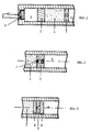
- Fig. 1 shows how a drop segment can be created.
- 1 is the storage container for the liquid to be pumped
- 2 is the piston or a membrane acting as a piston, which exerts all-round pressure on the liquid to be pumped in FIG. 1 from the developing gas 3 of the gas development cell 4.
- 6 is the room under ambient pressure into which the pumping takes place.
- the drop path is formed by letting the liquid to be conveyed run in the outflow line through a lyophobic orifice 5 or a lyophobic nozzle with an approximately conical opening cross section, the cone tip pointing to the delivery container 1. This is shown in Fig. 2. Under the influence of the excess pressure in FIG. 1, the liquid is pressed into the nozzle, forming a spherical cap-shaped surface, until a spherical drop separates after reaching the hemispherical shape and runs into the space 6. If there is an absorbent porous substance in room 6, the drop is absorbed as if by a sponge and transported further.
- FIG. 3 which consists of a lyophobic aperture 9 between two lyophilic porous bodies 8, has a similar effect.
- This arrangement also represents a pressure stage that must be overcome when the liquid passes between rooms 1 and 6.
- a liquid bridge which has formed under the influence of the overpressure between room 1 in the pinhole and connects the rooms 1 and 6, should tear off room 1 when the pressure drops.
- This is particularly easy if the hole in the pinhole can be supplied with gas. For this reason, it has proven to be expedient to produce the pinhole from fine-pore lyophobic material, then this fine-pore system can serve as a "compressed gas storage device" and absorb the gas displaced from the hole area.
- Polyethylene, polypropylene and polytetrafluoroethylene are plastics that repel some liquids, i.e. behave lyophobic. Such plastics can be used to produce fine-pored disks that are not flooded even at high liquid pressures of up to 10 bar and more. Perforated disks of the desired type can be produced by mechanically drilling a fine hole or by burning a thin channel with a laser beam.
- each drop that overcomes the pressure lock formed by perforated orifice 9 leads to the discharge of a correspondingly large volume of the liquid conveyed on other end of the wick. If it is an electrically conductive liquid, overcoming the pressure lock always creates an electrically conductive connection between rooms 1 and 6, which can be used to automatically control the conveying process.
- optical methods by measuring and registering the changed light scatter as the drop passes through the pressure lock.
- the light guide and optocoupler technology offers a variety of options for this, which can be carried out more or less comfortably at reasonable costs.
- the pressure stage according to the invention does not consist only of a single pore in a lyophobic disc can exist, but that it can be the totality of all pores in one of the liquid to be pumped opposite lyophobic diaphragm.
- the delivery pressure required to penetrate the diaphragm is determined by the capillary depression of the liquid in this diaphragm. After penetration of the diaphragm, the pressure energy converted into surface energy is destroyed with the formation of larger coherent drops or when the pores of a wettable disk are filled with heat.
Landscapes
- Health & Medical Sciences (AREA)
- Biomedical Technology (AREA)
- Hematology (AREA)
- Vascular Medicine (AREA)
- Engineering & Computer Science (AREA)
- Anesthesiology (AREA)
- Veterinary Medicine (AREA)
- Heart & Thoracic Surgery (AREA)
- Public Health (AREA)
- Life Sciences & Earth Sciences (AREA)
- Animal Behavior & Ethology (AREA)
- General Health & Medical Sciences (AREA)
- Fluid Mechanics (AREA)
- Physics & Mathematics (AREA)
- Infusion, Injection, And Reservoir Apparatuses (AREA)
Description
- Die vorliegende Erfindung betrifft ein Vorrichtung zur Injektion oder Infusion einer pharmazeutischen Lösung, mit einem Speicher, der die pharmazeutische Lösung beinhaltet und einer gasentwickelnden Zelle, bei der das durch einen elektrischen Strom erzeugte Wasserstoff- bzw. Sauerstoffgas die Lösung aus dem Speicher mit Hilfe eines beweglichen Kolbens oder einer flexiblen Membran verdrängt.
- Eine derartige Vorrichtung ist aus der DE-A-2 239 432 bekannt, die ein implantierbare Gerät für die Medikamentzufuhr in den menschlichen oder tierischen Körper vorschlägt, das sich in einer Ausführungsform der Volumenänderung durch elektrolytische Gaserzeugung zum Vortrieb eines Kolbens oder einer Membran bedient. Dabei ist vorgesehen, die dazu notwendige Energie aus einer Primärzelle bereitzustellen.
- In der DP-Anmeldung P 35 32 335.3 ist eine galvanische Zelle beschrieben, in der in einer zum Strom äquivalenten Menge Wasserstoff bzw. Sauerstoff erzeugt werden. Insbesondere kann die entwicklung von Wasserstoff ohne Zuführung von äußerer Energie erfolgen, wenn man eine Zink-elektrode in Kombination mit einer Wasserstoff-Elektrode verwendet, die beide in einem vorzugsweise alkalischen Elektrolyten betrieben werden. Durch Kurzschluß der Zelle über einen konstanten oder auch veränderlichen Widerstand lassen sich beliebige zeitliche Wasserstofferzeugungsprofile realisieren. Da dieses Geschehen auf kleinstem Raume erfolgt, ist die Methode besonders zur Injektion von pharmazeutischen Lösungen in den Körper hinein geeignet. Da die erzeugte Wasserstoffmenge äquivalent zum elektrischen Strom ist, können wegen dessen außerordentlich empfindlicher Dosierbarkeit kleinste Flüssigkeitsmengen mit entsprechender Genauigkeit gefördert werden.
- In der Human-Medizin wie auch in der Tier-Medizin spielt die therapeutische Behandlung durch Injektion oder Infusion von Arzneimitteln in die Körperflüssigkeit oder in das Gewebe eine bedeutende Rolle. Injektionen werden vom Arzt oder von besonders geschultem Personal vorgenommen und können daher besonders bei akuter, nichtstationärer Behandlung nur von Zeit zu Zeit vorgenommen werden. Die Injektion appliziert die wirksamen Substanzen stoßweise; der Körper muß sie also zur Erzielung einer Langzeitwirkung zwischenspeichern. Die Injektion darf nicht überdimensionieren und muß doch eine gewisse Zeit die Wirksamkeit der injizierten Substanz im Körper garantieren. Das erfordert sowohl Kompromisse bei dem chemischen Aufbau der Wirksubstanzen wegen deren Resorbierbarkeit vom Körper, der Zusammensetzung der Injektionslösung und deren therapeutischen Anwendung nach Häufigkeit und Menge der Injektion. Wünschenswert jedoch ist eine den jeweiligen Bedürfnissen angepaßte ständig ablaufende Injektion der Wirkstoffe in Form einer gesteuerten, wenn nicht gar geregelten Injektion.
- Bekanntestes Beispiel einer derartigen kontinuierlichen Injektionstherapie ist die Behandlung von Diabetikern mit Insulinlösung. Durch kontinuierliche Injektion lassen sich mit wesentlich geringeren Insulinmengen bessere Behandlungs erfolge erzielen als durch die bisherige schubweise Zuführung im Rhythmus der Mahlzeiten. Deshalb hat man Mikropumpen entwickelt, die mit Hilfe einer Batterie als Energievorrat ständig eint kleine Insulinmenge evt. programmgesteuert nach dem jeweiligen zeitlichen Bedarf in den Körper dosieren. Das Endziel dieser Entwicklung ist, die Glukosekonzentration im Blut mit geeigneten Sensoren ständig zu messen und die zugeführte Insulinmenge damit zu regeln, so daß der Körper stets die Insulinmenge seinem Bedarf entsprechend zugeführt bekommt. Allerdings sind verläßlich arbeitende langzeitstabile Glucosefühler noch nicht verfügbar.
- Es wurde nun gefunden, daß sich gasentwickelnde Zellen besonders gut zur Förderung von therapeutisch wirksamen flüssigkeiten in den menschlichen oder tierischen Körper eignen.
- Ein Problem entsteht lediglich dadurch, daß das Gasvolumen im Gegensatz zum Volumen der geförderten Flüssigkeit temperatur- und druckabhängig ist. Dieses hat zur Folge, daß z. B. ein Diabetes-Kranker mit einer auf Normaldruck eingestellten, kontinuierlichen oder zeitgesteuerten Insulinversorgung beim Betreten eines Flugzeugs eint Korrektur an der Dosiervorrichtung vornehmen muß, mit der der auf eine geometrische Höhe von 3 000 m eingestellte Kabinendruck berücksichtigt wird. eine solche Korrektur ist ohne weiteres möglich, wenn man mit Hilfe eines einfachen Rechnerchips aufgrund der Zustandsgleichung der Gase das erzeugte Gasvolumen auf den wirklichen Druck und die herrschende Temperatur umrechnet. Dieses aber erhöht den Aufwand im elektronischen Bereich des Gerätes und macht den einsatz einer, wenn auch kleinen, zusätzlichen Spannungsquelle in Form einer Batterie notwendig. Aufgabe der Vorliegenden Erfindung ist es, eine Vorrichtung der genannten Art so auszubilden, daß die Dosierbarkeit genauer und Kontrollierbarer ist und weitgehend unabhängig von den durch Temperatur und Luftdruck gegebenen Umweltbedingungen.
- Es wurde nun gefunden, daß man sich vom Umgebungsdruck und von der Umgebungstemperatur weitgehend unabhängig machen kann, wenn man die Oberflächenspannung σ der zu fördernden Flüssigkeit als eine konstante Gegendruckquelle und gewissermaßen als Druckstandard benutzt. Bekanntlich hat die Oberflächenspannung dieselbe Einheit in dyn/cm² wie der Druck. Man kann sie also in der beabsichtigten Funktion dann benutzen, wenn die Flüssigkeit gegen einen durch die Oberflächenspannung bestimmten Gegendruck gefördert wird. Dieses geschieht durch Auflösung des geförderten Flüssigkeitsstroms in einen Strom diskreter Flüssigkeitstropfen, der ggf. zu einem kontinuierlichen Strom wiedervereinigt werden kann.
- Gegendruck der Förderung in die Tropfenstrecke hinein ist der Laplace-DruckPL der Tröpfchen vom Radius R, gegeben durch die Gleichung

- In dieser Gleichung ist σ die Oberflächenspannung der zu fördernden Flüssigkeit, gemessen gegen eine Atmosphäse des gleichen dampfförmigen Mediums mit eingestelltem Partialdruck-Gleichgewicht. Besteht die zu fördernde Flüssigkeit nicht aus einer einheitlichen Lösung, sondern aus einer Lösung mehrerer Komponenten, so ist deren Dampfdruck im wesentlichen durch die am niedrigsten siedende Komponente bestimmt. Das gleiche gilt für die Förderung von Emulsionen fester und flüssiger Stoffe in Emulgationsflüssigkeiten, ggf. unter Zuhilfenahme von Emulgatoren. Auch die Förderung von Pasten kann so bewerkstelligt werden, wenn es gelingt, aufgrund deren rheologischer Eigenschaften eine Tropfenstrecke zu erzeugen.
- In Abb. 1 ist dargestellt, wie eine Tropfenstrecke erzeugt werden kann. 1 ist der Vorratsbehälter für die zu fördernde Flüssigkeit, 2 ist der Kolben oder eine als Kolben wirkende Membran, die von dem sich entwickelnden Gas 3 der Gasentwicklungszelle 4 einen allseitigen Druck auf die zu fördernde Flüssigkeit in 1 ausübt. 6 ist der Raum unter Umgebungsdruck, in den gefördert wird.
- Die Ausbildung der Tropfenstrecke erfolgt dadurch, daß man die zu fördernde Flüssigkeit in der Ausströmungsleitung durch eine lyophobe Lochblende 5 oder eine lyophobe Düse mit in etwa kegelförmigem Öffnungsquerschnitt laufen läßt, wobei die Kegelspitze auf den Förderbehälter 1 hinweist. Dieses ist in Abb. 2 dargestellt. Unter dem Einfluß des Überdrucks in 1 wird die Flüssigkeit unter Ausbildung einer kugelkalottenförmigen Oberfläche in die Düse hineingedrückt, bis sich nach Erreichen der Halbkugelform ein kugelförmiger Tropfen absondert und in den Raum 6 hineinläuft. Befindet sich im Raum 6 eine saugfähige poröse Substanz, so wird der Tropfen wie von einem Schwamm aufgenommen und weiter transportiert.
- Eine ähnliche Wirkung hat die Anordnung in Abb. 3, die aus einer lyophoben Lochblende 9 zwischen zwei lyophilen porösen Körpern 8 besteht. Auch diese Anordnung stellt eine Druckstufe dar, die beim Übergang der Flüssigkeit zwischen dem Räumen 1 und 6 überwunden werden muß. Bei der Betrachtung der Abb. 3 erkennt man, daß eine Flüssigkeitsbrücke, die sich unter dem Einfluß des Überdrucks zwischen Raum 1 in der Lochblende ausgebildet hat und die Räume 1 und 6 miteinander verbindet, bei Abfall des Überdrucks den Raum 1 wieder abreißen sollte. Das geht besonders leicht, wenn die Bohrung in der Lochblende mit Gas versorgt werden kann. es hat sich aus diesem Grunde als zweckmäßig erwiesen, die Lochblende aus feinporigem lyophoben Material herzustellen, dann kann dieses feinporige System als "Druckgasspeicher" dienen und das aus dem Lochbereich verdrängte Gas aufnehmen.
- Polyethylen, Polypropylen und Polytetrafluorethylen sind Kunststoffe, die sich gegen manche Flüssigkeiten abstoßend, d.h. lyophob verhalten. Man kann aus solchen Kunststoffen feinporige Scheiben herstellen, die selbst bei hohen flüssigkeitsdrucken bis zu 10 bar und mehr nicht überflutet werden. Man kann Lochscheiben der gewünschten Art dadurch herstellen, daß man mechanisch ein feines Loch einbohrt oder mit einem Laserstrahl einen dünnen Kanal einbrennt.
- Denkt man sich die an Raum 6 angrenzende lyophile Scheibe 8 zu einem Docht erweitert, der mit dem zu versorgenden Körpergewebe im Kapillardruckgleichgewicht steht, so führt jeder Tropfen, der die durch Lochblende 9 gebildete Druckschleuse überwindet, zum Abgang eines entsprechend großen Volumens der geförderten Flüssigkeit am anderen Ende des Dochtes. Handelt es sich um eine elektrisch leitende Flüssigkeit, so bewirkt die Überwindung der Druckschleuse jedes Mal die Herstellung einer elektrisch leitenden Verbindung zwischen den Räumen 1 und 6, die man zur selbsttätigen Kontrolle des Fördervorganges ausnutzen kann.
Eine solche Kontrolle ist jedoch auch mit optischen Methoden möglich, indem man die veränderte Lichtstreuung beim Durchwandern des Tropfens durch die Druckschleuse mißt und registriert. Die lichtleiter- und Optokopplertechnik bietet hierzu mannigfache Möglichkeiten, die nach den vertretbaren Kosten mehr oder weniger komfortabel ausgeführt werden können. - Aus der bisherigen Beschreibung kann man folgern, daß die erfindungsgemäße Druckstufe nicht nur aus einer einzelnen Pore in einer lyophoben Scheibe bestehen kann, sondern daß es sich hierbei um die Gesamtheit aller Poren in einem der zu fördernden Flüssigkeit gegenüber lyophoben Diaphragma handeln kann. Auch in diesem Fall ist der zum Durchdringen des Diaphragmas erforderliche Förderdruck durch die Kapillardepression der Flüssigkeit in diesem Diaphragma bestimmt. Nach dem Durchdringen des Diaphragmas wird die in Oberflächenenergie umgewandelte Druckenergie bei der Bildung größerer zusammenhängender Tropfen oder bei der Erfüllung der Poren einer benetzbaren Scheibe unter Wärmeentwicklung vernichtet.
Claims (4)
Applications Claiming Priority (2)
| Application Number | Priority Date | Filing Date | Title |
|---|---|---|---|
| DE3621846 | 1986-06-30 | ||
| DE19863621846 DE3621846A1 (de) | 1986-06-30 | 1986-06-30 | Gasbetriebene dosiervorrichtung |
Publications (2)
| Publication Number | Publication Date |
|---|---|
| EP0278954A1 EP0278954A1 (de) | 1988-08-24 |
| EP0278954B1 true EP0278954B1 (de) | 1992-01-22 |
Family
ID=6304020
Family Applications (1)
| Application Number | Title | Priority Date | Filing Date |
|---|---|---|---|
| EP19870903853 Expired - Lifetime EP0278954B1 (de) | 1986-06-30 | 1987-06-13 | Gasbetriebene dosiervorrichtung |
Country Status (4)
| Country | Link |
|---|---|
| EP (1) | EP0278954B1 (de) |
| AU (1) | AU7516287A (de) |
| DE (1) | DE3621846A1 (de) |
| WO (1) | WO1988000065A1 (de) |
Cited By (2)
| Publication number | Priority date | Publication date | Assignee | Title |
|---|---|---|---|---|
| DE10360186A1 (de) * | 2003-12-20 | 2005-08-04 | Max Wyssmann | Vorrichtung zur gezielten, steuerbaren Abgabe einer Flüssigkeit oder einer viskosen Masse |
| DE10360185A1 (de) * | 2003-12-20 | 2005-08-04 | Max Wyssmann | Vorrichtung zur gezielten, steuerbaren Abgabe oder zum Ansaugen einer Flüssigkeit oder einer viskosen Masse |
Families Citing this family (28)
| Publication number | Priority date | Publication date | Assignee | Title |
|---|---|---|---|---|
| DE3711714A1 (de) * | 1987-04-07 | 1988-10-27 | Winsel August | Vorrichtung zur foerderung pastoeser massen und fluessigkeiten und verfahren zur befuellung und zum betrieb |
| WO1988009187A1 (fr) * | 1987-05-18 | 1988-12-01 | Disetronic Ag | Appareil pour faire des perfusions |
| FR2631551A1 (fr) * | 1988-05-17 | 1989-11-24 | Soudant Jacques | Systeme pour faire une perfusion d'un liquide dans une voie sanguine notamment d'un etre humain |
| US5062834A (en) * | 1989-02-24 | 1991-11-05 | Product Development (S.G.Z.) Ltd | Device for dispensing a liquid particularly useful for delivering medicaments at a predetermined rate |
| DE4121351C2 (de) * | 1991-06-28 | 1994-12-15 | Winsel August | Fördervorrichtung mit einer Gasentwicklungszelle für fließfähige Medien |
| EP0598867B1 (de) * | 1992-06-15 | 1997-03-05 | WYSSMANN, Max | Vorrichtung zur gezielten, steuerbaren abgabe einer flüssigkeit oder einer viskosen masse |
| DE19519279A1 (de) * | 1994-12-07 | 1996-08-22 | Wolfgang Dr Med Wagner | Verfahren und Einrichtung zur Saug-Druckinjektion |
| DE19711605C1 (de) * | 1997-03-20 | 1998-06-25 | August Prof Dr Rer Nat Winsel | Gasbetriebene Fördervorrichtung für fließfähige Medien, bei der das Gasentwicklungssystem das Gas in einer vorgegebenen zeitlichen Menge vorzugsweise aus Gasentwicklungszellen erzeugt, mit einer Anzeige der Kolbenstellung |
| DE19907744A1 (de) * | 1999-02-23 | 2000-08-24 | Backes Claus H | Injektionsgerät |
| DE19909014C2 (de) * | 1999-03-02 | 2001-01-25 | August Winsel | Kolben und damit ausgerüstete, gasbetriebene Fördervorrichtung für fließfähige Medien, bei der das Gasentwicklungssystem das Gas in einer vorgegebenen zeitlichen Menge vorzugsweise aus Gasentwicklungszellen erzeugt |
| DE19925481A1 (de) * | 1999-06-03 | 2000-12-14 | August Winsel | Vorrichtung zur Sammlung von pastösen Massen, Flüssigkeiten, Gasen und mobilen Objekten |
| CA2370623C (en) | 1999-06-08 | 2004-07-20 | Medical Research Group, Inc. | Method and apparatus for infusing liquids using a chemical reaction in an implanted infusion device |
| DE10051232A1 (de) * | 2000-10-16 | 2002-04-25 | August Winsel | Sammelvorrichtung mit Diffusionssenke |
| KR100472577B1 (ko) * | 2001-11-02 | 2005-02-22 | 김용년 | 액체공급장치 |
| IL169807A (en) | 2005-07-21 | 2015-03-31 | Steadymed Ltd | Device for administering a drug |
| IL175460A (en) | 2006-05-07 | 2011-05-31 | Doron Aurbach | Drug delivery device |
| US9687186B2 (en) | 2005-07-21 | 2017-06-27 | Steadymed Ltd. | Drug delivery device |
| CN101432033A (zh) * | 2006-04-28 | 2009-05-13 | 皇家飞利浦电子股份有限公司 | 具有至少一种气体释放材料的微泵 |
| DE102007054753A1 (de) | 2007-07-30 | 2009-02-19 | Winsel, August, Prof. Dipl.-Phys. Dr. | Verfahren und Vorrichtung zur ökonomischen und ökologischen Bekämpfung von Schädlingen in und an Obst- und Nutzholzbäumen |
| ATE494026T1 (de) | 2008-03-10 | 2011-01-15 | Hoffmann La Roche | Medizinische vorrichtung und ladestation dafür |
| WO2012042517A1 (en) | 2010-09-27 | 2012-04-05 | Steadymed, Ltd. | Size-efficient drug-delivery device |
| ES2672239T3 (es) | 2012-03-15 | 2018-06-13 | Steadymed Ltd. | Reducción mejorada del dolor en el lugar de infusión para dispositivos de administración de fármacos |
| EP2827923B1 (de) | 2012-03-19 | 2018-12-26 | Steadymed Ltd. | Fluidverbindungsmechanismus für patchpumpen |
| US10463847B2 (en) | 2015-06-11 | 2019-11-05 | Steadymed Ltd. | Infusion set |
| CN107485762B (zh) * | 2017-09-07 | 2020-09-01 | 山东省千佛山医院 | 一种注射泵 |
| CN109771739B (zh) * | 2019-03-01 | 2021-02-26 | 浙江师范大学 | 一种压电片驱动的药品推注器 |
| CN109876239B (zh) * | 2019-03-01 | 2021-03-16 | 浙江师范大学 | 一种压电片驱动的注射系统 |
| CN110259539A (zh) * | 2019-06-06 | 2019-09-20 | 上海柯来浦能源科技有限公司 | 利用金属储氢材料氢能发电系统 |
Family Cites Families (5)
| Publication number | Priority date | Publication date | Assignee | Title |
|---|---|---|---|---|
| DE1099132B (de) * | 1958-08-02 | 1961-02-09 | Leitz Ernst Gmbh | Injektionsspritze |
| US4267836A (en) * | 1976-11-12 | 1981-05-19 | Whitney Douglass G | Injection device and method |
| AU5924380A (en) * | 1979-06-11 | 1980-12-18 | Unisearch Limited | Infusion apparatus |
| EP0209644A1 (de) * | 1985-05-02 | 1987-01-28 | Ivac Corporation | Elektrochemikalisch gesteuerte Arzneimittelabgabevorrichtung |
| DE3532335A1 (de) * | 1985-09-11 | 1987-03-12 | Winsel August | Galvanische zelle zur entwicklung von wasserstoff bzw. sauerstoff |
-
1986
- 1986-06-30 DE DE19863621846 patent/DE3621846A1/de active Granted
-
1987
- 1987-06-13 WO PCT/DE1987/000271 patent/WO1988000065A1/de not_active Ceased
- 1987-06-13 AU AU75162/87A patent/AU7516287A/en not_active Abandoned
- 1987-06-13 EP EP19870903853 patent/EP0278954B1/de not_active Expired - Lifetime
Cited By (2)
| Publication number | Priority date | Publication date | Assignee | Title |
|---|---|---|---|---|
| DE10360186A1 (de) * | 2003-12-20 | 2005-08-04 | Max Wyssmann | Vorrichtung zur gezielten, steuerbaren Abgabe einer Flüssigkeit oder einer viskosen Masse |
| DE10360185A1 (de) * | 2003-12-20 | 2005-08-04 | Max Wyssmann | Vorrichtung zur gezielten, steuerbaren Abgabe oder zum Ansaugen einer Flüssigkeit oder einer viskosen Masse |
Also Published As
| Publication number | Publication date |
|---|---|
| DE3621846C2 (de) | 1992-04-02 |
| EP0278954A1 (de) | 1988-08-24 |
| AU7516287A (en) | 1988-01-29 |
| DE3621846A1 (de) | 1988-01-21 |
| WO1988000065A1 (fr) | 1988-01-14 |
Similar Documents
| Publication | Publication Date | Title |
|---|---|---|
| EP0278954B1 (de) | Gasbetriebene dosiervorrichtung | |
| DE69121881T2 (de) | Hautelektrodenaufbau und dazugehöriges gerät zur transdermalen verabreichung von heilmitteln | |
| DE69231073T2 (de) | Durch mittels elektrolyse in hydrogel erzeugten gasdruck angetriebenes infusionssystem | |
| DE69115431T2 (de) | Abgabevorrichtung für flüssiges Material | |
| DE2652026C2 (de) | Gerät zur Infusion von Flüssigkeiten | |
| DE60028531T2 (de) | Fluidaustragungsvorrichtung mit stabilisiertem fluidfluss | |
| DE2626348C3 (de) | Implantierbare Dosiereinrichtung | |
| DE2721752C2 (de) | In einen menschlichen oder tierischen Körper implantierbares Gerät zur Infusion einer medizinischen Flüssigkeit | |
| DE2626294C3 (de) | Implantierbare Dosiereinrichtung | |
| DE3850972T2 (de) | Prozess und system und messzellen-anordnung zur glukose-bestimmung. | |
| DE60310244T2 (de) | Membranpumpe mit dehnbarer pumpenmembran | |
| EP1733676B1 (de) | Sensorsystem sowie Anordnung und Verfahren zur Überwachung eines Inhaltsstoffs, insbesondere Glucose in Körpergewebe | |
| DE2513467C3 (de) | Gerät zur Infusion von Flüssigkeiten in den menschlichen oder tierischen Körper | |
| DE3446909C2 (de) | ||
| DE69833229T2 (de) | Elektrochemische Pumpe insbesondere zur Medikamentenverabreichung | |
| DE60018726T2 (de) | Vorrichtung zur iontophoretischen verabreichung von medikamenten mit internen sensoren | |
| EP0742025A1 (de) | Verfahren zum Befüllen einer Pumpenkammer einer gasdruckbetriebenen Medikamentenpumpe | |
| DE2552446B2 (de) | Gerät zur Infusion von Flüssigkeiten in den menschlichen oder tierischen Körper | |
| EP0025005A1 (de) | Vorrichtung zum Fördern und Dosieren kleinster Flüssigkeitsmengen | |
| WO1999032174A1 (de) | Tragbarer medikamentspender zur zeitversetzten verabreichung von injektions- oder infusionspräparaten | |
| EP2582290A1 (de) | Befeuchtete sensorkontakteinheit | |
| DE10004496A1 (de) | Vorrichtung und Verfahren zur Injektion eines Medikamentes | |
| DE102017216581B4 (de) | Mikrofluidische Vorrichtung für Zellkulturexperimente und Verwendungen hiervon | |
| DE3713061A1 (de) | In den koerper eines patienten implantierbares medikamentendosiergeraet | |
| WO1999002211A1 (de) | Spraymechanismus für dosier-sprayflaschen |
Legal Events
| Date | Code | Title | Description |
|---|---|---|---|
| PUAI | Public reference made under article 153(3) epc to a published international application that has entered the european phase |
Free format text: ORIGINAL CODE: 0009012 |
|
| 17P | Request for examination filed |
Effective date: 19880526 |
|
| AK | Designated contracting states |
Kind code of ref document: A1 Designated state(s): CH FR GB IT LI SE |
|
| 17Q | First examination report despatched |
Effective date: 19900307 |
|
| GRAA | (expected) grant |
Free format text: ORIGINAL CODE: 0009210 |
|
| AK | Designated contracting states |
Kind code of ref document: B1 Designated state(s): CH FR GB IT LI SE |
|
| REG | Reference to a national code |
Ref country code: CH Ref legal event code: PUE Owner name: GCT GAS-CELL-TEC AG |
|
| RAP2 | Party data changed (patent owner data changed or rights of a patent transferred) |
Owner name: GCT GAS-CELL-TEC AG |
|
| RIN2 | Information on inventor provided after grant (corrected) |
Free format text: WINSEL, AUGUST, PROF. DR. |
|
| ITF | It: translation for a ep patent filed | ||
| GBT | Gb: translation of ep patent filed (gb section 77(6)(a)/1977) | ||
| ET | Fr: translation filed | ||
| PLBI | Opposition filed |
Free format text: ORIGINAL CODE: 0009260 |
|
| 26 | Opposition filed |
Opponent name: DISETRONIC AG MEDIZINISCH-TECHNISCHE GERAETE Effective date: 19920725 |
|
| PLBM | Termination of opposition procedure: date of legal effect published |
Free format text: ORIGINAL CODE: 0009276 |
|
| STAA | Information on the status of an ep patent application or granted ep patent |
Free format text: STATUS: OPPOSITION PROCEDURE CLOSED |
|
| 27C | Opposition proceedings terminated |
Effective date: 19940104 |
|
| EAL | Se: european patent in force in sweden |
Ref document number: 87903853.7 |
|
| REG | Reference to a national code |
Ref country code: GB Ref legal event code: IF02 |
|
| REG | Reference to a national code |
Ref country code: CH Ref legal event code: PFA Owner name: GCT GAS-CELL-TEC AG Free format text: GCT GAS-CELL-TEC AG#FELDSTRASSE 37#3360 HERZOGENBUCHSEE (CH) -TRANSFER TO- GCT GAS-CELL-TEC AG#HOCHSTRASSE 7#3360 HERZOGENBUCHSEE (CH) |
|
| PGFP | Annual fee paid to national office [announced via postgrant information from national office to epo] |
Ref country code: GB Payment date: 20050702 Year of fee payment: 19 |
|
| PGFP | Annual fee paid to national office [announced via postgrant information from national office to epo] |
Ref country code: CH Payment date: 20060526 Year of fee payment: 20 |
|
| PGFP | Annual fee paid to national office [announced via postgrant information from national office to epo] |
Ref country code: FR Payment date: 20060530 Year of fee payment: 20 |
|
| PGFP | Annual fee paid to national office [announced via postgrant information from national office to epo] |
Ref country code: SE Payment date: 20060607 Year of fee payment: 20 |
|
| PG25 | Lapsed in a contracting state [announced via postgrant information from national office to epo] |
Ref country code: GB Free format text: LAPSE BECAUSE OF NON-PAYMENT OF DUE FEES Effective date: 20060613 |
|
| PGFP | Annual fee paid to national office [announced via postgrant information from national office to epo] |
Ref country code: IT Payment date: 20060630 Year of fee payment: 20 |
|
| GBPC | Gb: european patent ceased through non-payment of renewal fee |
Effective date: 20060613 |
|
| REG | Reference to a national code |
Ref country code: CH Ref legal event code: PL |
|
| EUG | Se: european patent has lapsed |