EP0280242A2 - Image reading apparatus - Google Patents
Image reading apparatus Download PDFInfo
- Publication number
- EP0280242A2 EP0280242A2 EP88102583A EP88102583A EP0280242A2 EP 0280242 A2 EP0280242 A2 EP 0280242A2 EP 88102583 A EP88102583 A EP 88102583A EP 88102583 A EP88102583 A EP 88102583A EP 0280242 A2 EP0280242 A2 EP 0280242A2
- Authority
- EP
- European Patent Office
- Prior art keywords
- document
- components
- reading apparatus
- image reading
- molded member
- Prior art date
- Legal status (The legal status is an assumption and is not a legal conclusion. Google has not performed a legal analysis and makes no representation as to the accuracy of the status listed.)
- Ceased
Links
Images
Classifications
-
- H—ELECTRICITY
- H04—ELECTRIC COMMUNICATION TECHNIQUE
- H04N—PICTORIAL COMMUNICATION, e.g. TELEVISION
- H04N1/00—Scanning, transmission or reproduction of documents or the like, e.g. facsimile transmission; Details thereof
- H04N1/04—Scanning arrangements, i.e. arrangements for the displacement of active reading or reproducing elements relative to the original or reproducing medium, or vice versa
- H04N1/19—Scanning arrangements, i.e. arrangements for the displacement of active reading or reproducing elements relative to the original or reproducing medium, or vice versa using multi-element arrays
- H04N1/191—Scanning arrangements, i.e. arrangements for the displacement of active reading or reproducing elements relative to the original or reproducing medium, or vice versa using multi-element arrays the array comprising a one-dimensional [1D] array
- H04N1/192—Simultaneously or substantially simultaneously scanning picture elements on one main scanning line
- H04N1/193—Simultaneously or substantially simultaneously scanning picture elements on one main scanning line using electrically scanned linear arrays, e.g. linear CCD arrays
- H04N1/1935—Optical means for mapping the whole or part of a scanned line onto the array
- H04N1/1937—Optical means for mapping the whole or part of a scanned line onto the array using a reflecting element, e.g. a mirror or a prism
-
- G—PHYSICS
- G06—COMPUTING OR CALCULATING; COUNTING
- G06K—GRAPHICAL DATA READING; PRESENTATION OF DATA; RECORD CARRIERS; HANDLING RECORD CARRIERS
- G06K7/00—Methods or arrangements for sensing record carriers, e.g. for reading patterns
- G06K7/10—Methods or arrangements for sensing record carriers, e.g. for reading patterns by electromagnetic radiation, e.g. optical sensing; by corpuscular radiation
- G06K7/10544—Methods or arrangements for sensing record carriers, e.g. for reading patterns by electromagnetic radiation, e.g. optical sensing; by corpuscular radiation by scanning of the records by radiation in the optical part of the electromagnetic spectrum
- G06K7/10712—Fixed beam scanning
- G06K7/10722—Photodetector array or CCD scanning
-
- H—ELECTRICITY
- H04—ELECTRIC COMMUNICATION TECHNIQUE
- H04N—PICTORIAL COMMUNICATION, e.g. TELEVISION
- H04N1/00—Scanning, transmission or reproduction of documents or the like, e.g. facsimile transmission; Details thereof
- H04N1/04—Scanning arrangements, i.e. arrangements for the displacement of active reading or reproducing elements relative to the original or reproducing medium, or vice versa
- H04N1/12—Scanning arrangements, i.e. arrangements for the displacement of active reading or reproducing elements relative to the original or reproducing medium, or vice versa using the sheet-feed movement or the medium-advance or the drum-rotation movement as the slow scanning component, e.g. arrangements for the main-scanning
- H04N1/121—Feeding arrangements
-
- H—ELECTRICITY
- H04—ELECTRIC COMMUNICATION TECHNIQUE
- H04N—PICTORIAL COMMUNICATION, e.g. TELEVISION
- H04N1/00—Scanning, transmission or reproduction of documents or the like, e.g. facsimile transmission; Details thereof
- H04N1/04—Scanning arrangements, i.e. arrangements for the displacement of active reading or reproducing elements relative to the original or reproducing medium, or vice versa
- H04N1/19—Scanning arrangements, i.e. arrangements for the displacement of active reading or reproducing elements relative to the original or reproducing medium, or vice versa using multi-element arrays
- H04N1/191—Scanning arrangements, i.e. arrangements for the displacement of active reading or reproducing elements relative to the original or reproducing medium, or vice versa using multi-element arrays the array comprising a one-dimensional [1D] array
- H04N1/192—Simultaneously or substantially simultaneously scanning picture elements on one main scanning line
- H04N1/193—Simultaneously or substantially simultaneously scanning picture elements on one main scanning line using electrically scanned linear arrays, e.g. linear CCD arrays
Definitions
- the present invention relates to an optical image reading apparatus such as a facsimile and OCR or more specifically to an optical reading apparatus in which an optical system and a document transport system are built into a unit.
- the object of the present invention is to provide an optical image reading apparatus whose optical system and document transport system are supported on one molded member to permit accurate reading of the image on a document.
- an image reading apparatus has a molded member containing blocks for supporting components of an optical system which leads light reflected from a document to a reading element and blocks for supporting components of a document transport system which conveys the document.
- the image reading apparatus of the present invention it is possible to mount the optical system components and document transport system components on the molded member integrally formed blocks for supporting said components respectively.
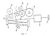
- Fig. 1 shows the schematic construction of an optical system for reading the image on a document and of a document transport system.
- the broken lines "-------" indicate components not supported on a molded member, the chain lines “ “ indicate optical path, and the solid lines “ “ indicate components supported on the molded member.
- P is document
- 1 is a lamp illuminating the document P.
- the numerals 2, 3 and 4 are mirrors
- 5 is a lens
- 7 is a CCD image sensor
- 8 is a document transport roller
- 9 is a document feed roller
- 12 is a roller driven by the document transport roller 8
- 13 is a second document transport roller
- 14 is a roller driven by the second document transport roller 13.
- the image bearing side of the document P is illuminated by the lamp 1 as the document 1 is being transmitted by the document feed roller 9 and the transport roller 8.
- the light from the lamp 1 is reflected by the document surface, led via the mirrors 2, 3 and 4 to the lens 5 and read by the CCD image sensor 7.
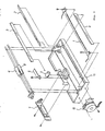
- Fig. 2 is an exploded view showing the components to be supported on an integrally molded member.
- the same parts as those of Fig. 1 are allotted with the same reference numbers.
- the numeral 11 is the molded member having blocks for mounting the lamp 1, the mirrors 2, 3 and 4, the lens 5, the CCD image sensor 7, the document transport roller 8 and the document feed roller 9.
- the numeral 6 is a set plate for retaining the lens 5 in the specified block of the molded member 11.
- 10 is a document transport system-driving motor. Means for mounting the set plate 6 and the motor 10 are also formed in the molded member 11.
- the image reading apparatus of the present invention comprises the optical system and the document transport system supported on one integrally molded member, allowing the optical system and transport system components to be positioned accurately.
- the image reading apparatus of the present invention reads the image on a document accurately and is simple in construction. The simplicity in construction helps realize a smaller and lower cost image reading apparatus and reduce the number of production processes.
Landscapes
- Engineering & Computer Science (AREA)
- Multimedia (AREA)
- Signal Processing (AREA)
- Physics & Mathematics (AREA)
- Electromagnetism (AREA)
- Health & Medical Sciences (AREA)
- General Health & Medical Sciences (AREA)
- Toxicology (AREA)
- Artificial Intelligence (AREA)
- Computer Vision & Pattern Recognition (AREA)
- General Physics & Mathematics (AREA)
- Theoretical Computer Science (AREA)
- Facsimile Scanning Arrangements (AREA)
Abstract
An optical image reading apparatus for reading image information on a document (p) by leading light reflected from the optically scanned document to a reading element (7), wherein components of an optical system (1-6) for leading the reflected light to the reading element (p) and components of a document transport system (8, 9) for conveying the document (p) are mounted on a molded member (11) having blocks for supporting the components.
Description
- The present invention relates to an optical image reading apparatus such as a facsimile and OCR or more specifically to an optical reading apparatus in which an optical system and a document transport system are built into a unit.
- Conventionally, there is no optical reading equipment with an optical system and a document transport system built in one body to allow accurate reading of the image on a document.
- The object of the present invention is to provide an optical image reading apparatus whose optical system and document transport system are supported on one molded member to permit accurate reading of the image on a document.
- To achieve the above object, according to the present invention, an image reading apparatus has a molded member containing blocks for supporting components of an optical system which leads light reflected from a document to a reading element and blocks for supporting components of a document transport system which conveys the document.
- According to the image reading apparatus of the present invention, it is possible to mount the optical system components and document transport system components on the molded member integrally formed blocks for supporting said components respectively.
- The present invention will become more fully understood from the detailed description given hereinbelow and the accompanying drawings which are given by way of illustration only, and thus are not limitative of the present invention and wherein:
- Fig. 1 is a drawing showing schematic construction of an embodiment of the present invention; and
- Fig. 2 is an exploded view showing each component to be supported on a molded member.
- An embodiment of the optical image reading apparatus of the present invention is described in detail below with reference to the attached drawings.
- Fig. 1 shows the schematic construction of an optical system for reading the image on a document and of a document transport system. The broken lines "-------" indicate components not supported on a molded member, the chain lines "" indicate optical path, and the solid lines " " indicate components supported on the molded member.

- Referring to Fig. 1, P is document, and 1 is a lamp illuminating the document P. The
numerals document transport roller 8, 13 is a second document transport roller, and 14 is a roller driven by the seconddocument transport roller 13. - The image bearing side of the document P is illuminated by the
lamp 1 as thedocument 1 is being transmitted by the document feed roller 9 and the transport roller 8. - The light from the
lamp 1 is reflected by the document surface, led via themirrors lens 5 and read by theCCD image sensor 7. - Fig. 2 is an exploded view showing the components to be supported on an integrally molded member. The same parts as those of Fig. 1 are allotted with the same reference numbers. The
numeral 11 is the molded member having blocks for mounting thelamp 1, themirrors lens 5, theCCD image sensor 7, the document transport roller 8 and the document feed roller 9. - The numeral 6 is a set plate for retaining the
lens 5 in the specified block of the moldedmember 11. 10 is a document transport system-driving motor. Means for mounting the set plate 6 and themotor 10 are also formed in the moldedmember 11. - As understood from the above, the image reading apparatus of the present invention comprises the optical system and the document transport system supported on one integrally molded member, allowing the optical system and transport system components to be positioned accurately. As a result, the image reading apparatus of the present invention reads the image on a document accurately and is simple in construction. The simplicity in construction helps realize a smaller and lower cost image reading apparatus and reduce the number of production processes.
- While only certain embodiments of the present invention have been described, it will be apparent to those skilled in the art that various changes and modifications may be made therein without departing from the spirit and scope of the present invention as claimed.
Claims (2)
1. An optical image reading apparatus for reading image information on a document (p) by leading light reflected from the optically scanned document to a reading element (7), wherein components of an optical system (1-6) for leading said reflected light to said reading element (7) and components of a document transport system (8, 9) for conveying said document (p) are mounted on a molded member (11) having blocks for supporting said components.
2. The image reading apparatus of the claim 1, wherein said reading element (7) is a CCD.
Applications Claiming Priority (2)
| Application Number | Priority Date | Filing Date | Title |
|---|---|---|---|
| JP62041128A JPS63207268A (en) | 1987-02-23 | 1987-02-23 | Image reader |
| JP41128/87 | 1987-02-23 |
Publications (2)
| Publication Number | Publication Date |
|---|---|
| EP0280242A2 true EP0280242A2 (en) | 1988-08-31 |
| EP0280242A3 EP0280242A3 (en) | 1991-01-16 |
Family
ID=12599803
Family Applications (1)
| Application Number | Title | Priority Date | Filing Date |
|---|---|---|---|
| EP19880102583 Ceased EP0280242A3 (en) | 1987-02-23 | 1988-02-22 | Image reading apparatus |
Country Status (2)
| Country | Link |
|---|---|
| EP (1) | EP0280242A3 (en) |
| JP (1) | JPS63207268A (en) |
Cited By (2)
| Publication number | Priority date | Publication date | Assignee | Title |
|---|---|---|---|---|
| EP0485975A3 (en) * | 1990-11-14 | 1992-12-09 | Canon Kabushiki Kaisha | Image reading device and image information processing apparatus |
| US5526141A (en) * | 1991-04-26 | 1996-06-11 | Canon Kabushiki Kaisha | Original image reading apparatus having device for conveying an original at a position deviated from an original reading position of a contact-type reading sensor |
Families Citing this family (1)
| Publication number | Priority date | Publication date | Assignee | Title |
|---|---|---|---|---|
| JP2899140B2 (en) * | 1991-07-26 | 1999-06-02 | シャープ株式会社 | Optical reader |
Family Cites Families (2)
| Publication number | Priority date | Publication date | Assignee | Title |
|---|---|---|---|---|
| JPS56106467A (en) * | 1980-01-26 | 1981-08-24 | Toshiba Corp | Facsimile transmitter |
| DE3524811A1 (en) * | 1984-07-14 | 1986-01-23 | Canon K.K., Tokio/Tokyo | Image-scanning device |
-
1987
- 1987-02-23 JP JP62041128A patent/JPS63207268A/en active Pending
-
1988
- 1988-02-22 EP EP19880102583 patent/EP0280242A3/en not_active Ceased
Cited By (4)
| Publication number | Priority date | Publication date | Assignee | Title |
|---|---|---|---|---|
| EP0485975A3 (en) * | 1990-11-14 | 1992-12-09 | Canon Kabushiki Kaisha | Image reading device and image information processing apparatus |
| US5475504A (en) * | 1990-11-14 | 1995-12-12 | Canon Kabushiki Kaisha | Image reading device detachable from main body |
| US5526141A (en) * | 1991-04-26 | 1996-06-11 | Canon Kabushiki Kaisha | Original image reading apparatus having device for conveying an original at a position deviated from an original reading position of a contact-type reading sensor |
| EP0511004B1 (en) * | 1991-04-26 | 1998-08-05 | Canon Kabushiki Kaisha | Original image reading device and image information processing apparatus having the same |
Also Published As
| Publication number | Publication date |
|---|---|
| JPS63207268A (en) | 1988-08-26 |
| EP0280242A3 (en) | 1991-01-16 |
Similar Documents
| Publication | Publication Date | Title |
|---|---|---|
| US4989099A (en) | Image information reading apparatus | |
| US4839730A (en) | Image reading apparatus | |
| EP1164536A3 (en) | An apparatus for reading an optical code | |
| EP0535585A2 (en) | Image sensor | |
| MY138010A (en) | Contact type image sensor, producing method of the same, and information processing apparatus | |
| US11627229B2 (en) | Original reading apparatus | |
| US5121226A (en) | Portable image scanner | |
| US7218427B2 (en) | Image reading apparatus | |
| JPS6410775A (en) | Original reader | |
| EP0280242A2 (en) | Image reading apparatus | |
| EP0093763A1 (en) | Optical scanner for color facsimile. | |
| US5019918A (en) | Portable image scanner | |
| US6426808B1 (en) | Feeding device | |
| JP3006229B2 (en) | Scanner document collection device | |
| EP0154322A2 (en) | Electronic graphic detecting head | |
| EP1021031A2 (en) | Device for detecting images | |
| EP0333320A3 (en) | Apparatus for scanning reading of documents of different formats | |
| GB2143635A (en) | Chart reader | |
| JP3033987B2 (en) | Document reading device | |
| JPS62219873A (en) | Image reader | |
| ATE43449T1 (en) | OPTICAL MULTILINE READER FOR MACHINE CHARACTER RECOGNITION. | |
| JPH01122263A (en) | Carriage | |
| EP0517007A1 (en) | Facsimile device | |
| JPH0270169A (en) | Original reading device | |
| WO1995002889A1 (en) | Palm scanner having folded optics and a guide rail |
Legal Events
| Date | Code | Title | Description |
|---|---|---|---|
| PUAI | Public reference made under article 153(3) epc to a published international application that has entered the european phase |
Free format text: ORIGINAL CODE: 0009012 |
|
| 17P | Request for examination filed |
Effective date: 19880222 |
|
| AK | Designated contracting states |
Kind code of ref document: A2 Designated state(s): DE GB |
|
| PUAL | Search report despatched |
Free format text: ORIGINAL CODE: 0009013 |
|
| AK | Designated contracting states |
Kind code of ref document: A3 Designated state(s): DE GB |
|
| 17Q | First examination report despatched |
Effective date: 19921007 |
|
| STAA | Information on the status of an ep patent application or granted ep patent |
Free format text: STATUS: THE APPLICATION HAS BEEN REFUSED |
|
| 18R | Application refused |
Effective date: 19940303 |