EP0281615B1 - Procede scenographique et processeur pour la production rapide d'images - Google Patents
Procede scenographique et processeur pour la production rapide d'images Download PDFInfo
- Publication number
- EP0281615B1 EP0281615B1 EP87906227A EP87906227A EP0281615B1 EP 0281615 B1 EP0281615 B1 EP 0281615B1 EP 87906227 A EP87906227 A EP 87906227A EP 87906227 A EP87906227 A EP 87906227A EP 0281615 B1 EP0281615 B1 EP 0281615B1
- Authority
- EP
- European Patent Office
- Prior art keywords
- data
- pixel
- voxel
- data base
- display screen
- Prior art date
- Legal status (The legal status is an assumption and is not a legal conclusion. Google has not performed a legal analysis and makes no representation as to the accuracy of the status listed.)
- Expired - Lifetime
Links
Images


Classifications
-
- G—PHYSICS
- G06—COMPUTING OR CALCULATING; COUNTING
- G06T—IMAGE DATA PROCESSING OR GENERATION, IN GENERAL
- G06T1/00—General purpose image data processing
-
- G—PHYSICS
- G09—EDUCATION; CRYPTOGRAPHY; DISPLAY; ADVERTISING; SEALS
- G09B—EDUCATIONAL OR DEMONSTRATION APPLIANCES; APPLIANCES FOR TEACHING, OR COMMUNICATING WITH, THE BLIND, DEAF OR MUTE; MODELS; PLANETARIA; GLOBES; MAPS; DIAGRAMS
- G09B9/00—Simulators for teaching or training purposes
- G09B9/02—Simulators for teaching or training purposes for teaching control of vehicles or other craft
- G09B9/08—Simulators for teaching or training purposes for teaching control of vehicles or other craft for teaching control of aircraft, e.g. Link trainer
- G09B9/30—Simulation of view from aircraft
- G09B9/301—Simulation of view from aircraft by computer-processed or -generated image
-
- G—PHYSICS
- G06—COMPUTING OR CALCULATING; COUNTING
- G06T—IMAGE DATA PROCESSING OR GENERATION, IN GENERAL
- G06T15/00—Three-dimensional [3D] image rendering
- G06T15/10—Geometric effects
- G06T15/20—Perspective computation
Definitions
- This invention relates generally to image generation and more particularly to image generation systems which incorporate computer processing of stored imagery data.
- One type of image generation system is based on a data base of interconnected flat polygon descriptions of objects comprising the scenery with monocolor, smooth shaded and textured polygons. These systems produce cartoon-like images and data bases being largely hand composed are expensive to create and excessively large if attempting to reproduce the true complexity of real nature.
- a voxel is located by its base position in the data base grid and contains information for processing to form pixel data. For example, color and/or intensity and elevation is associated with each voxel.
- a system which utilizes voxel data bases for generating synthetic images of a scene is described in FR-A-2553543. Accordingly, an analysis of the scene to be displayed is made by firstly defining a plurality of scanning planes, each of them including as a common line the vertical line from a view-point to the previously stored ground data and each extending radially outwardly from the common vertical line in every possible "flight directions" of the viewpoint. Subsequently, a "scan beam" takes sample points according to a constant increment of distance from the common vertical line following the linear-path at which each scanning plane intersects the stored data base.
- the object of the present invention is, in contrast, to further improve the generation of realistic images or scenes at frame rates sufficient to create the appearance of continuous motion.
- the invention provides in accordance with a first embodiment imagery data of a scene in the form of data for pixels of a display screen, by the use of a voxel data base.
- a host simulation system provides data as to the viewer's eye position relative to the display screen, which determines the simulated field of view (FOV) and the voxel data base is organized into a two-dimensional grid for each of a plurality of resolution levels representing ground coordinate positions.
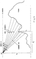
- the display screen comprises rows and columns of pixels and a plane projected through the eyepoint and a given pixel column intercepts the data base grid in a line which defines a given linear linear scanning path.
- the voxel data base is effectively scanned along the linear path at a data base resolution proportional to the projected pixel size on the data base and the scanned voxel data is processed into data for successive pixels, the respective boundaries of which are projected onto the data base surface encountered in the linear scan of the data base. Compensation for effects such as elevation (vertical) perspective and roll are performed following the computation of the pixel data.
- One of the advantages of the invention is that separation of the horizontal and vertical perspective calculation allows for scanning the data base in a linear fashion independent of the data base contents or, more specifically, of data base values of elevation (Z), thus a highly “pipeline” computer architecture is possible.
- This "pipe” completely expresses the process in many successive processing stages so that at each clock cycle, substantially all aspects of the processing algorithms are processed in parallel for successive data elements.
- a further parallelism in processing is achieved by the feature that by processing the linear data base scans in the proper order there is only a uni-directional interdependence which results in a straightforward precedence relationship in the derived pixel data between successive scans. This allows many of the scans to be processed in parallel, providing for a second dimension of parallelism to be implemented.
- the combination of these features thus allows a practical implementation of a "real time" scene generator working with a data base with sufficient descriptive capability to produce photographic like scenes.
- a further advantage of the present invention is that a method and an apparatus are provided for efficiently processing voxel or gridded data bases so as to generate realistic images or scenes at frame rates sufficient to create the appearance of continuous motion.
- Yet another advantage is that a method and an apparatus are provided for generating realistic images or scenes wherein parallel data processing is effectively utilized.
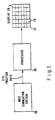
- the invention provides imagery data of a scene in the form of data for pixels 20 of a display screen 22 by the use of a voxel data base organized in a two-dimensional grid 24 representing ground coordinate positions.
- a voxel data base organized in a two-dimensional grid 24 representing ground coordinate positions.
- a host simulation system 26 provides data as to the viewer's eye point relatiave to the display screen 22, to processor (scene generator) 40 which in accordance with the subject invention processes the voxel data base to provide pixel data in the proper formats for display of high quality imagery on display screen 22.
- Host simulator system 26 may include a host computer (not shown) and a joystick driven zero model (not shown) in a trainer simulation application, for example.
- a plane projected through the eyepoint and a given pixel column intersects the data base grid in a line which defines a linear scanning path (see FIG.6).
- the voxel data base is effectively scanned along the linear path at a data base resolution proportional to the projected pixel size on the data base grid and the scanned voxel data is processed into data for successive pixels.
- the respective pixel bottom and top boundaries are projected onto the data base surface encountered in the linear scan of the data base to define which voxels are associated with each pixel.
- Each subprocess in the pipeline process is further broken down into a pipelined subprocess.
- the large dynamic data base memory 70 (FIG. 3a) is implemented by dynamic MOS memories which have cycle times greater than desired processing clock times.
- the orderly way in which the algorithm scans across the data base in x, y coordinates makes for a highly efficient interleaving memory design structure.
- the choice of a voxel data base organized into a two dimensional grid representing ground coordinate positions optimizes this interleaving capability.
- FIGS. 2a and 2b illustrate how a display pixel projected to ground data base voxels.
- the pixel color is the integration of 3 whole voxels plus a large portion of the lst voxel and a small portion of the last (5th) voxel comprising the pixel footprint 29 on the surface of the ground data base.
- the dominant sizing parameter in the described system is the pitch angle value at which in more shallow (closer to horizontal) angles load management techniques have to be employed, thus degrading the generated scene quality in some way.
- the most effective load management method is to use more course voxels, thus reducing the voxel count per pixel. This is usually not noticeable in factors up to two or even four.
- Another option is to slow the scene generation rate in increments of 1/60 th of a second, again not very noticeable at low slant angles straight ahead.) If for instance, it is desired to go up to a pitch angle of 11° below the horizon before load management is required; then, since voxels are 1.5 times a pixel width on the average (kept between ⁇ 1 and ⁇ 2, i.e., the voxel size/resolution is chosen greater than one pixel width and less than two pixel widths), the projected pixel will average four voxels in length. Again, for example, in a 480 ⁇ 480 pixel display, 33 ms update rate picture, an average of approximately 8 million pixels per second are processed. Therefore, we will need four parallel voxel pipes, each running at an effective average rate of 8 million voxels per second to produce the required pixels.
- the process of real time scene generation from a voxel data base consists of accessing all of the data base descriptor elements (voxels) within view and integrating each visible voxel luminance value into the appropriate screen pixel in proportion to its contribution to that pixel. Depending on the slant angle of view and scene content, this means accessing and processing several tens of millions of voxels per second to create the display.
- the pixel footprint width is utilized to determine the proper hierarchy level of voxel data to process thereby keeping the number of voxels processed independent of slant range.
- the image generation algorithm partitions the scene generation process into many but identical tasks allowing execution on parallel identical processors.
- the algorithm also allows for all of the stages in the individual task to be calculated simultaneously on succeeding data elements in a long pipeline structure.
- the system architecture utilizes parallelism in two dimensions making practical the high rate of computation required for voxel based scene generation.
- FIGS. 3a and 3b shows the front of the pipe structure as a multiple pipe configuration narrowing to a single pipe for the latter half of the processing.
- functional modular elements 50 through 57 are shown in FIGS. 3a and 3b as illustrating four pipes (parallel processing channels).
- coordinate address generator 50 is shown as comprising the four modular elements 50a, 50b, 50c and 50d, each of which operate in respective processor pipes.
- Dynamic data base memory 70 is shown as comprising numerous submodules and buffers 67 and 68 as each comprising two submodules (although in single pipe configuration).
- data base elements voxels
- the data traffic reduces to much smaller and predictable number at the point that pixels are produced and a single pipe structure is sufficient to meet the remaining processing requirements.
- the pipe length is built in a functionally modular fashion with a common interface protocol for the data path between physical elements, and a common control system. This provides one architecture for a range of functional additions or changes. This modularity is also of great assistance in fault diagnosis and maintenance procedures because the functions are physically isolated from each other with centrally accessible test inputs and outputs on a module basis that allows rapid fault detection/fault isolation.
- the parallel pipe structure also brings modularity to hardware requirements allowing a common architecture to be economically tailored to a given application.
- the parallel identical pipes also provide a failsoft fault tolerant capability that provides degraded operation thus ensuring higher system availability.
- the processor execution is entirely under the control of the pipe manager 42 along with its frame and column parameter generator 44.
- the pipe manager has a list of tasks (the can columns) and a collection of resources (the pipe processors).
- the manager's job is to keep the resources busy on the tasks (which are variable in duration) to complete a frame of display information).
- An interconnection (switching) networks 72, 74 before and after the active data base memory 70 allows all pipes to share access to the common data base memory.
- the memory is made up of many interleaved submodules in order to obtain the memory access bandwidth required.
- Data definitive of the immediate view area i.e., the area for immediate processing
- the active data base random access memory 70 by high speed data transfer from the data base memory 82 (library) which holds data definitive of the gaming area of interest (i.e., the area for which image/scene generation might be required).
- Memory 82 may comprise a plurality of magnetic disk memory units, for example. This transfer is performed under the control of the data base manager 42 which uses current and extrapolated eye point calculations for data base access control.
- the Address Generator 50 utilize the Column Parameter Generator 44 output of initial condition for a pixel column path projected on the active data base, to emit a stream of ground coordinates. These are translated to real memory page and sub-page addresses to obtain voxel data at the appropriate hierarchy level. If the hierarchy level stored is at a lower resolution than required by the visibility processor 56, (as defined by the pixel footprint 29 computed from slant range) the intensity and/or color interpolator 54 and z interpolator 55 generate an appropriate voxel by utilizing the distance to the low resolution voxel corners and computing a new intermediate intensity (and or color) and z value which is inserted in the voxel stream.
- the Pattern Processor 53 accesses the referenced vertical pattern and inserts these voxels within the stream.
- the final result is a stream of appropriately sized voxels for a display image column.
- the Visibility Processor 56 processes this stream to determine voxel visibility and perform vertical intensity averaging of multiple voxels within the pixel footprint.
- the horizontal averaging is an effect of utilizing the appropriate hierarchy since each hierarchy was produced by averaging the next higher resolution hierarchy voxel intensities.
- the individual pixel information is then passed into a single pipeline where vertical perspective offset correction is added at 60 for correct total perspective, haze is inserted at 61 and at 62 the image is rotated to account for eye point roll angle.
- the system maintains proper horizontal perspective in the initial part of the pipelined process.
- a plane is projected through the eyepoint and the pixel column (see FIG. 6).
- the path is the line where this plane intersects the base plane (data base grid 24).
- the paths from the projection of all the columns diverge as they extend through the data base.
- voxels farther from the eyepoint will appear smaller and closer together when projected onto the screen.
- This is a true geometric projection which maintains true horizontal perspective.
- This process also produces a correct vertical perspective if the pitch angle of the viewing screen equals zero. For other pitch angles proper vertical perspective is maintained by a characteristic of the algorithm which maps voxels onto screen pixels by a post displacement correction.
- the algorithm proceeds up (Z dimension) a tall voxel, it is deflecting each pixel into the appropriate column.
- the near to far scan of the algorithm allows for far scenery uncovered by deflected near objects to fill in the uncovered areas. If a closer object were deflected into a column, it would take precedence over the distant voxels and would occlude them.
- the columns are calculated from the center (in downward pitch) out to the sides. As each pixel is calculated, there may or may not be a deflection.
- the algorithm checks a stored fill value to determine whether or not the pixel has already been filled.
- any pixel that has already been filled must have been filled by a pixel deflected from an inner column. That inner pixel must have been from a closer voxel because it was deflected farther than the current pixel. Therefore, it should occlude the pixel calculated from the current voxel which is then regarded as hidden and simply discarded.
- the fill value is also used to anti-alias edges in profile. When it is detected that a pixel is partially filled by an edge, it is stored in the frame buffer 67 with this partial fill value. Later in the scan, background voxels generate a pixel candidate for this position;which fills the balance of the fill value and adjusts the intensity accordingly.
- the system of the invention uses a data base representation which at once can describe the "photographic" scene detail needed and can help in the scene generation process.
- This is basically a grid of elements each with an expression of elevation and color and/or intensity (brightness only value for monochrome systems) and altitude information.
- four adjacent elements (2x and 2y) color and/or intensity values are integrated and their maximum elevation value assigned to create a higher level (more coarse) hierarchy of the data base.
- This integration is repeatedly performed to produce a number of levels in the data base hierarchy.
- This off line process which expands the data base only fractionally, is the first step toward total ground integration in a pixels subtended area.
- the algorithm next provides for an orderly scan of the area of interest in the data base.
- the straight line scans of successive data base elements serves to optimize the efficiency of a highly interleaved memory.
- the scan is performed in a direction away from the eye position along radials spaced equal to the width of a column of display screen pixels, projected to the data level (see FIG. 6).
- the scans are performed at a data base hierarchy level which provides a slightly larger voxel than pixel; thus ensuring that all of the grid is observed.
- successive voxels that are subtended by a pixel are integrated and normalized to complete the total grid integration.
- Visible voxels increase in vertical angular viewpoint as the voxel scan progresses radially outward.
- the voxel luminances contribute to successive pixel rows.
- a reasonable approximation to a true perspective for many applications and especially those with a narrow field of view (FOV) is to constrain all of the straight line of voxels scanned in the base grid plane to fall into a single column of pixels in the display.
- a latter section deals with vertical perspective correction for correct perspective in wide field of views.
- the voxel Prior to processing, but after retrieving a voxel from the data base memory, the voxel (as an option) is passed through a pattern insertion stage 52 where marked voxels can call up selected vertical patterns to insert in the voxel stream. These can represent stationary above ground objects such as trees, buildings, vehicles, etc., with multiple color values in the vertical dimension, including transparent sections.
- An optional additional capability for moving objects is provided by a means in the coordinate position scan generator to match the current generated position against the head of a sorted list of window areas. Each window area represents the footprint of a moveable object (that is, the window coordinates can be moved).
- a parallel process obtains the actual rotated base of the identified object with its base elements marked to access the appropriate patterns via the same mechanism as the stationary pattern insertion stage.
- a common object base description can be used in many places in the data base at any orientation. Also, it shares patterns with all other objects, moving or stationary.
- haze is generated as a function of distance and vertical looking angle.
- Clouds are inserted at 68 by scanning with the same mechanism on alternate data base in the common data base memory 70.
- This alternate data base describes a cloud pattern in three dimensions just as the ground is described.
- the cloud pattern is purposely very course in order to generate fuzzy clouds with translucent edges.
- This course data base occupies very little data base memory and requires a small frame buffer for assembling the cloud view, which is only 1/64 as large as the ground scene buffer since the cloud linear resolution is 1/8 the ground scene resolution.
- an interpolation 66 smooths the cloud scene between the course pixels and merges at 64 in the ground pixels where cloud data is missing. Pixel range comparison is used to determine which is visible.
- the world coordinates system represented by X, Y, and Z defines the voxel data base.
- (X, Y) maps the data location and Z is the elevation.
- the screen coordinate represented by j and i is the 2-D coordinate where the final images are displayed.
- Variable j refers to the column number of the screen and i to the pixel number.
- FIG. 4 shows the two coordinate systems and the (eye) viewing position (X E , Y E , Z E ).
- the voxel type (gridded) data base is used to describe the natural terrain and man-made structures and is created by digitizing aerial photographs into a very fine grid. This is then overlaid onto the corresponding digital terrain elevation data.
- a voxel type data base (1) hardware efficiency is improved if the memory can be organized (highly interleaved) such that the scanning process can access the memory with minimal contention; and (2) natural terrain texturing is improved if the data originates from aerial photography; the details of the terrain textures are built-in.
- the voxel data base contains the color and/or brightness information and the elevation value of that location.
- the color of the pixel is the area integration of the voxels subtended by the pixel.
- Part of the voxel integration can be performed at the data base preparation time (i.e., as an off-line process), by adding several hierarchies of voxels to the data base. Starting with the original digitized data, a higher-level hierarchy of voxels is created by averaging the color of four adjacent (two in X and Y) voxels. This process is repeated to create a number of levels in the binary hierarchy. Initially, during the voxels processing, we choose a hierarchy level whose voxel size is comparable to the projected pixel size. This accomplishes the integration in horizontal cross view direction.
- the data base need not be prepared with all required resolution levels at all places. In many areas, it is unnecessary to provide high resolution detail or it may be unavailable due to photographic limitations or memory limitations.
- the processor at scan time will attempt at each voxel access, the hierarchy of resolution appropriate to the slant range and projected pixel size. If this is unavailable, then the next highest hierarchy which is available will be selected. Since a lower hierarchy of resolution is never selected, total horizontal intensity integration is always accomplished. Voxels will never fall between scan columns and be missed.
- a process of horizontal interpolation is performed by linearly interpolating between the four corner intensity values of the voxel according to the scan position within the voxel (FIG. 5). Also, to obtain smooth terrain profiles this same function is performed on the Z elevation values of the four corners of the voxel. In order to avoid multiple data base accesses at run time, these four intensity and Z values are stored with each voxel. Except in places of discontinuities these corner values are merely copies of the adjacent voxel values and are thus redundant.
- the data is stored in memory 82 (FIG. 3a) in a compressed format without this redundacy. It is expanded “on the fly” as the data is transferred into the RAM data memory 70.
- the data base created from direct, overhead aerial photography does not supply the color information on vertical edges resulting from discontinuities in elevation such as buildings, bridges, cliffs, etc. These vertical edges correspond to multiple color elevation values at the same terrain location. However, the corresponding voxel can contain only one elevation value, and only one color value. Therefore, whenever there is a vertical edge in the data base, a separate data base or pattern must be supplied to accommodate it.
- This data may also be created from digitized photography or may be synthetically composed. Without significant loss of realism, the same pattern data, i.e., the windowed wall of a building, can be used for more than one vertical edge.
- the voxels in the footprint of the object are each replaced with a pointer to a vertical pattern in pattern memory.
- every image i.e., frame
- every image is uniquely characterized by the eye position: X E , Y E , Z E , the attitude: R (roll), P (pitch), Y (yaw), and the FOV (field of view).
- the FOV is fixed for a sequence of images. Only X E , Y E , Z E , R, P, Y vary from frame to frame. It is there six parameters that are received every 1/30 second from an external source, i.e., a joystick driven aero model (not shown) which is part of host simulation system 26 (FIG. 1).
- the images that are first generated are for zero roll angle.
- the rotation to produce the true final image is performed after this original image is assembled.
- a prerotated image must be generated. That is, in the prerotated image the grid lines are rotated with respect to the edge of the image such that the final rotation will put the output image into a rectangular format with grid parallel to the edge of the image.
- the FOV′ for frame A′ B′ C′ D′ is greater than or equal to FOV. This will be referred to as apparent field of view.
- V j For pixel column j, there is a corresponding angle V j , defined as the angle between the center row view direction EG and the frame direction EO (see FIG. 7).
- the starting point (Xstj, Ystj) can be calculated (see FIG. 6).
- the increments in X-direction, X j ; in Y-direction, Y j ; and in range, R j are then calculated.
- the scanning will cross one minor axis grid line (at the appropriate grid resolution) each step, i.e., if the major axis of the scanning line is X (the angle between the scanning line and X-axis is less than 45 degrees), X j will be set to 1. Otherwise, Y j is set to 1.
- ⁇ j which is the angle V j projected to the ground along the direction perpendicular to the frame view direction (see FIG. 8)
- the minor axis increment is then equal to the tangent of the angle between this scanning line on the ground plane'and the major axis.
- X j and Y j are both scaled later by the coordinate scan generator to the proper hierarchy level.
- pixel boundaries within the column vertically and calculated so that start and stop points for the integration are defined.
- the boundaries of pixel ( j , i ) are ⁇ j , i and ⁇ j , i + 1 ⁇ ⁇ j , i is the angle between the view direction of pixel ( j , i ) and the horizon plane through eye positions (see FIG. 8).
- the end of a column scanning is determined when the number of increments counted in B j , i calculated exceeds L j + M j , where L j is the number of pixels above the center row and M j is the number below.
- voxels are stored in "pages" of 128 ⁇ 128 voxels (16K words). Each page represents an area of world coordinate space of size proportional to the resolution hierachy of the voxels in the page. A page of voxels at a resolution of one foot will represent 128 by 128 feet of real world space.
- a memory mangagement unit 80 By their hierarchy number and base coordinate position and dynamically loaded in the data base RAM 70 (FIG. 3a) as the footprint of the viewing area moves across the ground.
- a translation unit 51 checks a set of valid page tables to see if real memory 82 contains the page representing the desired hierarchy and coordinate position. If not, it finds the next best available.
- the actual page physical base address is obtained and supplemented with the within page individual voxel address. This resulting address is sent to the multiple common data base memory modules 70 via a multiplexing/demultiplexing swith 72.
- the memory modules access the addressed voxel and forward it through switch 74 to the resolution requesting pipe for processing.
- the data for each voxel contains a pattern flag bit. If this flag is not sent, the voxel is an ordinary ground voxel, which contains a Z values of the four corners relative to a page related base Z, and the color of the four corners of the voxel. Except for discontinuities, these Zs and colors are just copies of the neighboring corners. If the pattern flag is set, then this voxel will have multiple Z values and colors, i.e., a vertical pattern is needed. The voxel data now will contain an index that points to the proper pattern to access. These patterns are retrieved from a shared pattern memory 53 and inserted in the voxel stream as successive voxels of varing heights one above another at the same X, Y location.
- Functional module 54 interpolates the intensity and/or color and Z values between the four corners of the voxel using an extended resolution pair of X, Y offset values (into the voxel), provided in a path 75 from the address generator which bypasses the data base memory.
- the pipe line module 56 two immediate tests are made: (1) pixel end test and (2) pixel visibility test, to help in making the decision for color integration.
- the pixel end test is to determine whether the voxel is outside the current pixel boundary.
- FIG. 9 illustrates examples of both situations.
- This unit utilizes the ground distance, R g , as computed by the number of steps taken in the data base and each step size (resolution size) and the voxel z value to compute a voxel surface angle ⁇ y .
- ⁇ y is compared against the pixel boundary angle ⁇ ji which are fixed but relative to the boresite pitch.
- the visibility test compares the current ⁇ y against the previously determined visible voxel angle.
- the radial color integration is illustrated by FIG. 10.
- the color of the shaded voxels should all be integrated into the pixel i.
- a straightforward implementation is to simply sum all the colors of the shaded voxels and then normalized. This is generally adequate when the scene is textured terrain, but when the scene is, say, a dark building against a bright background, the edge of the building will appear jagged, and will have a cartoonish motion. To correct this, the angular portion of the pixel that the voxel subtends is calculated, then the color is weighted by this proportion. Conversely, voxels which overlap pixel boundaries are distributed to those pixels proportional to the amount of each pixel covered.
- a vertical perspective correction stage 60 is provided.
- the vertical perspective correction is the displacement, d, (FIG. 11) between P and P′ which correspond to the displacement on the image screen to another column.
- This form is used to derive the displaced column value because the first term is a constant for the entire column and can be supplied by the column parameter generation 44 (FIG. 3a), Rs is derived for each point for other purposes, ⁇ is the vertical pixel angle from a table and Z E is a frame parameter constant for the entire frame.
- Haze effect is dependent on the slant range of the pixel contents and pitch angle of the pixel relative to the horizon. It is calculated at the same pipeline states where rotation is performed.
- the haze function is described by:
- the gridded pixels calculated are not the same as the pixels for the output image.
- the calculated pixels are correct for a prerotated grid. After rotation by some arbitary amount, these pixels now fall not regularly on the grid scanned out in the final display format, but rather in locations between these pixels. If arbitrarily moved back into the scan grid structure, a strong aliasing effect would be exhibited.
- new pixel positions are calculated with two extra bits, for example, of accuracy in both x and y. These bits, representing an offset from the pixel home location, are stored with the pixel color and/or intensity value in this ping pong double output buffer 69. After a frame is built in one of these buffers, it is then used to scan for the output picture while the other buffer is used to construct the next frame. While the buffer is being scanned to create the output video, two ajacent rows are actually scanned simultaneously to obtain the information necessary to accomplish the antialising algorithm.
- FIG. 12 shows grid point A in the rotated image for which the antialiasing rotation is to be performed, and C1, C2, C3, and C4, which are four pixels in the original image rotated by R into display coordinates, x, y.
- the color values of these four pixels are integrated into the next pixel at A according to the distances d1, d2, d3, and d4, inversely weighted by their offsets from A (note that the number of contributions to one single output grid may not always be four). It is dependent upon the rotation angle. The greatest number of contributions is five, but it could be as small as two.
Landscapes
- Engineering & Computer Science (AREA)
- Theoretical Computer Science (AREA)
- Physics & Mathematics (AREA)
- General Physics & Mathematics (AREA)
- Educational Administration (AREA)
- Business, Economics & Management (AREA)
- Aviation & Aerospace Engineering (AREA)
- Educational Technology (AREA)
- Computer Hardware Design (AREA)
- Computing Systems (AREA)
- Geometry (AREA)
- Computer Graphics (AREA)
- Image Generation (AREA)
- Processing Or Creating Images (AREA)
Abstract
Claims (7)
Applications Claiming Priority (2)
| Application Number | Priority Date | Filing Date | Title |
|---|---|---|---|
| US92585686A | 1986-09-11 | 1986-09-11 | |
| US925856 | 1986-09-11 |
Publications (2)
| Publication Number | Publication Date |
|---|---|
| EP0281615A1 EP0281615A1 (fr) | 1988-09-14 |
| EP0281615B1 true EP0281615B1 (fr) | 1991-09-11 |
Family
ID=25452350
Family Applications (1)
| Application Number | Title | Priority Date | Filing Date |
|---|---|---|---|
| EP87906227A Expired - Lifetime EP0281615B1 (fr) | 1986-09-11 | 1987-07-24 | Procede scenographique et processeur pour la production rapide d'images |
Country Status (9)
| Country | Link |
|---|---|
| EP (1) | EP0281615B1 (fr) |
| JP (1) | JPH0776990B2 (fr) |
| KR (1) | KR910008461B1 (fr) |
| CA (1) | CA1276297C (fr) |
| DE (1) | DE3772968D1 (fr) |
| ES (1) | ES2005312A6 (fr) |
| IL (1) | IL83697A (fr) |
| TR (1) | TR23655A (fr) |
| WO (1) | WO1988002155A1 (fr) |
Families Citing this family (3)
| Publication number | Priority date | Publication date | Assignee | Title |
|---|---|---|---|---|
| EP0397071A3 (fr) * | 1989-05-10 | 1993-06-16 | Honeywell Inc. | Procédé pour la représentation topographique en perspective d'une position |
| TW317954U (en) * | 1992-10-01 | 1997-10-11 | Hudson Soft Co Ltd | Image processing system including a processor side memory and a display side memory |
| CN109492007A (zh) * | 2018-11-09 | 2019-03-19 | 南京天辰礼达电子科技有限公司 | 一种压实施工质量精细化图片快速生成算法 |
Family Cites Families (3)
| Publication number | Priority date | Publication date | Assignee | Title |
|---|---|---|---|---|
| GB2051525A (en) * | 1979-06-15 | 1981-01-14 | Redifon Simulation Ltd | C.G.I.-Surface textures |
| US4489389A (en) * | 1981-10-02 | 1984-12-18 | Harris Corporation | Real time video perspective digital map display |
| FR2553543B2 (fr) * | 1982-03-25 | 1988-09-16 | Dassault Electronique | Procede pour engendrer a bord d'un aeronef une image synthetique du terrain survole |
-
1987
- 1987-07-24 DE DE8787906227T patent/DE3772968D1/de not_active Expired - Fee Related
- 1987-07-24 KR KR1019880700524A patent/KR910008461B1/ko not_active Expired
- 1987-07-24 EP EP87906227A patent/EP0281615B1/fr not_active Expired - Lifetime
- 1987-07-24 JP JP62505647A patent/JPH0776990B2/ja not_active Expired - Lifetime
- 1987-07-24 WO PCT/US1987/001781 patent/WO1988002155A1/fr not_active Ceased
- 1987-08-31 IL IL83697A patent/IL83697A/xx not_active IP Right Cessation
- 1987-09-09 TR TR87/0613A patent/TR23655A/xx unknown
- 1987-09-10 ES ES8702613A patent/ES2005312A6/es not_active Expired
- 1987-09-10 CA CA000546570A patent/CA1276297C/fr not_active Expired - Lifetime
Non-Patent Citations (1)
| Title |
|---|
| Proceedings of the IEEE National Aerospace and Electronics Conference, NAECON 1984, 21-25 May 1984, volume 2 of 2, IEEE, (US), O. Marvel et al.: "Image synthesization for simulation, and training", pages 884-890 * |
Also Published As
| Publication number | Publication date |
|---|---|
| DE3772968D1 (de) | 1991-10-17 |
| KR910008461B1 (ko) | 1991-10-15 |
| WO1988002155A1 (fr) | 1988-03-24 |
| TR23655A (tr) | 1990-05-29 |
| ES2005312A6 (es) | 1989-03-01 |
| JPH01501179A (ja) | 1989-04-20 |
| IL83697A (en) | 1991-08-16 |
| KR880701923A (ko) | 1988-11-07 |
| EP0281615A1 (fr) | 1988-09-14 |
| JPH0776990B2 (ja) | 1995-08-16 |
| CA1276297C (fr) | 1990-11-13 |
Similar Documents
| Publication | Publication Date | Title |
|---|---|---|
| US4825391A (en) | Depth buffer priority processing for real time computer image generating systems | |
| US5363475A (en) | Image generator for generating perspective views from data defining a model having opaque and translucent features | |
| KR0172462B1 (ko) | 렌더링 및 와핑 영상 생성 시스템 및 방법 | |
| DE3782160T2 (de) | Digitales simulationssystem zur erzeugung von realistischen szenen. | |
| US5699497A (en) | Rendering global macro texture, for producing a dynamic image, as on computer generated terrain, seen from a moving viewpoint | |
| Weinhaus et al. | Texture mapping 3D models of real-world scenes | |
| CA2313267C (fr) | Methode permettant d'ombrer les cartes numeriques en temps reel | |
| US20020101419A1 (en) | System and method of processing digital terrain information | |
| US20030038811A1 (en) | System and method of line sampling object scene information | |
| WO2006058165A2 (fr) | Restitution optimisee de corps en mouvement dynamiques | |
| US5719598A (en) | Graphics processor for parallel processing a plurality of fields of view for multiple video displays | |
| EP0281615B1 (fr) | Procede scenographique et processeur pour la production rapide d'images | |
| EP0250588B1 (fr) | Correction d'ensemble de distorsions dans un systeme d'imagerie en temps reel | |
| Guedes et al. | Real-time rendering of photo-textured terrain height fields | |
| JPH0241785B2 (fr) | ||
| EP0450978A2 (fr) | Appareil pour générer un affichage visuel | |
| GB2265801A (en) | Image generator | |
| Kortenjan et al. | Size equivalent cluster trees (sec-trees) realtime rendering of large industrial scenes | |
| Mower | Implementing an augmented scene delivery system | |
| Weiman | Advanced Weapon System (AWS) Sensor Prediction Techniques Study. Volume I | |
| Lee et al. | View-dependent simplification of complex urban scenes using weighted quadtrees | |
| GB2265804A (en) | Scan converting rectilinear edged objects | |
| GB2265802A (en) | Image generator | |
| GB2265803A (en) | Processing model data | |
| GB2242810A (en) | Addressing a texture memory |
Legal Events
| Date | Code | Title | Description |
|---|---|---|---|
| PUAI | Public reference made under article 153(3) epc to a published international application that has entered the european phase |
Free format text: ORIGINAL CODE: 0009012 |
|
| 17P | Request for examination filed |
Effective date: 19880510 |
|
| AK | Designated contracting states |
Kind code of ref document: A1 Designated state(s): CH DE FR GB IT LI SE |
|
| 17Q | First examination report despatched |
Effective date: 19891025 |
|
| GRAA | (expected) grant |
Free format text: ORIGINAL CODE: 0009210 |
|
| AK | Designated contracting states |
Kind code of ref document: B1 Designated state(s): CH DE FR GB IT LI SE |
|
| ET | Fr: translation filed | ||
| REF | Corresponds to: |
Ref document number: 3772968 Country of ref document: DE Date of ref document: 19911017 |
|
| ITF | It: translation for a ep patent filed | ||
| PLBE | No opposition filed within time limit |
Free format text: ORIGINAL CODE: 0009261 |
|
| STAA | Information on the status of an ep patent application or granted ep patent |
Free format text: STATUS: NO OPPOSITION FILED WITHIN TIME LIMIT |
|
| 26N | No opposition filed | ||
| PGFP | Annual fee paid to national office [announced via postgrant information from national office to epo] |
Ref country code: FR Payment date: 19940609 Year of fee payment: 8 |
|
| PGFP | Annual fee paid to national office [announced via postgrant information from national office to epo] |
Ref country code: SE Payment date: 19940615 Year of fee payment: 8 |
|
| PGFP | Annual fee paid to national office [announced via postgrant information from national office to epo] |
Ref country code: GB Payment date: 19940620 Year of fee payment: 8 |
|
| PGFP | Annual fee paid to national office [announced via postgrant information from national office to epo] |
Ref country code: DE Payment date: 19940627 Year of fee payment: 8 Ref country code: CH Payment date: 19940627 Year of fee payment: 8 |
|
| EAL | Se: european patent in force in sweden |
Ref document number: 87906227.1 |
|
| PG25 | Lapsed in a contracting state [announced via postgrant information from national office to epo] |
Ref country code: GB Effective date: 19950724 |
|
| PG25 | Lapsed in a contracting state [announced via postgrant information from national office to epo] |
Ref country code: SE Effective date: 19950725 |
|
| PG25 | Lapsed in a contracting state [announced via postgrant information from national office to epo] |
Ref country code: LI Effective date: 19950731 Ref country code: CH Effective date: 19950731 |
|
| REG | Reference to a national code |
Ref country code: CH Ref legal event code: PL |
|
| GBPC | Gb: european patent ceased through non-payment of renewal fee |
Effective date: 19950724 |
|
| PG25 | Lapsed in a contracting state [announced via postgrant information from national office to epo] |
Ref country code: DE Effective date: 19960402 |
|
| EUG | Se: european patent has lapsed |
Ref document number: 87906227.1 |
|
| PG25 | Lapsed in a contracting state [announced via postgrant information from national office to epo] |
Ref country code: FR Effective date: 19960430 |
|
| REG | Reference to a national code |
Ref country code: FR Ref legal event code: ST |
|
| REG | Reference to a national code |
Ref country code: FR Ref legal event code: ST |
|
| REG | Reference to a national code |
Ref country code: FR Ref legal event code: ST |
|
| PG25 | Lapsed in a contracting state [announced via postgrant information from national office to epo] |
Ref country code: IT Free format text: LAPSE BECAUSE OF NON-PAYMENT OF DUE FEES;WARNING: LAPSES OF ITALIAN PATENTS WITH EFFECTIVE DATE BEFORE 2007 MAY HAVE OCCURRED AT ANY TIME BEFORE 2007. THE CORRECT EFFECTIVE DATE MAY BE DIFFERENT FROM THE ONE RECORDED. Effective date: 20050724 |