EP0282599A1 - Method of preparing nc part program for laser machining - Google Patents
Method of preparing nc part program for laser machining Download PDFInfo
- Publication number
- EP0282599A1 EP0282599A1 EP87905642A EP87905642A EP0282599A1 EP 0282599 A1 EP0282599 A1 EP 0282599A1 EP 87905642 A EP87905642 A EP 87905642A EP 87905642 A EP87905642 A EP 87905642A EP 0282599 A1 EP0282599 A1 EP 0282599A1
- Authority
- EP
- European Patent Office
- Prior art keywords
- corner
- machining
- corner portion
- part program
- creating
- Prior art date
- Legal status (The legal status is an assumption and is not a legal conclusion. Google has not performed a legal analysis and makes no representation as to the accuracy of the status listed.)
- Granted
Links
Images




Classifications
-
- G—PHYSICS
- G05—CONTROLLING; REGULATING
- G05B—CONTROL OR REGULATING SYSTEMS IN GENERAL; FUNCTIONAL ELEMENTS OF SUCH SYSTEMS; MONITORING OR TESTING ARRANGEMENTS FOR SUCH SYSTEMS OR ELEMENTS
- G05B19/00—Program-control systems
- G05B19/02—Program-control systems electric
- G05B19/18—Numerical control [NC], i.e. automatically operating machines, in particular machine tools, e.g. in a manufacturing environment, so as to execute positioning, movement or co-ordinated operations by means of program data in numerical form
- G05B19/4093—Numerical control [NC], i.e. automatically operating machines, in particular machine tools, e.g. in a manufacturing environment, so as to execute positioning, movement or co-ordinated operations by means of program data in numerical form characterised by part programming, e.g. entry of geometrical information as taken from a technical drawing, combining this with machining and material information to obtain control information, named part program, for the NC machine
-
- G—PHYSICS
- G05—CONTROLLING; REGULATING
- G05B—CONTROL OR REGULATING SYSTEMS IN GENERAL; FUNCTIONAL ELEMENTS OF SUCH SYSTEMS; MONITORING OR TESTING ARRANGEMENTS FOR SUCH SYSTEMS OR ELEMENTS
- G05B19/00—Program-control systems
- G05B19/02—Program-control systems electric
- G05B19/18—Numerical control [NC], i.e. automatically operating machines, in particular machine tools, e.g. in a manufacturing environment, so as to execute positioning, movement or co-ordinated operations by means of program data in numerical form
- G05B19/4093—Numerical control [NC], i.e. automatically operating machines, in particular machine tools, e.g. in a manufacturing environment, so as to execute positioning, movement or co-ordinated operations by means of program data in numerical form characterised by part programming, e.g. entry of geometrical information as taken from a technical drawing, combining this with machining and material information to obtain control information, named part program, for the NC machine
- G05B19/40937—Numerical control [NC], i.e. automatically operating machines, in particular machine tools, e.g. in a manufacturing environment, so as to execute positioning, movement or co-ordinated operations by means of program data in numerical form characterised by part programming, e.g. entry of geometrical information as taken from a technical drawing, combining this with machining and material information to obtain control information, named part program, for the NC machine concerning programming of machining or material parameters, pocket machining
-
- G—PHYSICS
- G05—CONTROLLING; REGULATING
- G05B—CONTROL OR REGULATING SYSTEMS IN GENERAL; FUNCTIONAL ELEMENTS OF SUCH SYSTEMS; MONITORING OR TESTING ARRANGEMENTS FOR SUCH SYSTEMS OR ELEMENTS
- G05B2219/00—Program-control systems
- G05B2219/30—Nc systems
- G05B2219/34—Director, elements to supervisory
- G05B2219/34098—Slope fitting, fairing contour, curve fitting, transition
-
- G—PHYSICS
- G05—CONTROLLING; REGULATING
- G05B—CONTROL OR REGULATING SYSTEMS IN GENERAL; FUNCTIONAL ELEMENTS OF SUCH SYSTEMS; MONITORING OR TESTING ARRANGEMENTS FOR SUCH SYSTEMS OR ELEMENTS
- G05B2219/00—Program-control systems
- G05B2219/30—Nc systems
- G05B2219/35—Nc in input of data, input till input file format
- G05B2219/35244—Select in corner different program according to inner, outer machining
-
- G—PHYSICS
- G05—CONTROLLING; REGULATING
- G05B—CONTROL OR REGULATING SYSTEMS IN GENERAL; FUNCTIONAL ELEMENTS OF SUCH SYSTEMS; MONITORING OR TESTING ARRANGEMENTS FOR SUCH SYSTEMS OR ELEMENTS
- G05B2219/00—Program-control systems
- G05B2219/30—Nc systems
- G05B2219/36—Nc in input of data, input key till input tape
- G05B2219/36215—Insert automatically program sequence, for corner execution, avoid machining error
-
- G—PHYSICS
- G05—CONTROLLING; REGULATING
- G05B—CONTROL OR REGULATING SYSTEMS IN GENERAL; FUNCTIONAL ELEMENTS OF SUCH SYSTEMS; MONITORING OR TESTING ARRANGEMENTS FOR SUCH SYSTEMS OR ELEMENTS
- G05B2219/00—Program-control systems
- G05B2219/30—Nc systems
- G05B2219/43—Speed, acceleration, deceleration control ADC
- G05B2219/43129—Speed as function of curvature, in curves, corners smaller than in straight line
-
- G—PHYSICS
- G05—CONTROLLING; REGULATING
- G05B—CONTROL OR REGULATING SYSTEMS IN GENERAL; FUNCTIONAL ELEMENTS OF SUCH SYSTEMS; MONITORING OR TESTING ARRANGEMENTS FOR SUCH SYSTEMS OR ELEMENTS
- G05B2219/00—Program-control systems
- G05B2219/30—Nc systems
- G05B2219/43—Speed, acceleration, deceleration control ADC
- G05B2219/43147—Control power of tool as function of speed, velocity of movement
-
- G—PHYSICS
- G05—CONTROLLING; REGULATING
- G05B—CONTROL OR REGULATING SYSTEMS IN GENERAL; FUNCTIONAL ELEMENTS OF SUCH SYSTEMS; MONITORING OR TESTING ARRANGEMENTS FOR SUCH SYSTEMS OR ELEMENTS
- G05B2219/00—Program-control systems
- G05B2219/30—Nc systems
- G05B2219/45—Nc applications
- G05B2219/45165—Laser machining
-
- G—PHYSICS
- G05—CONTROLLING; REGULATING
- G05B—CONTROL OR REGULATING SYSTEMS IN GENERAL; FUNCTIONAL ELEMENTS OF SUCH SYSTEMS; MONITORING OR TESTING ARRANGEMENTS FOR SUCH SYSTEMS OR ELEMENTS
- G05B2219/00—Program-control systems
- G05B2219/30—Nc systems
- G05B2219/50—Machine tool, machine tool null till machine tool work handling
- G05B2219/50109—Soft approach, engage, retract, escape, withdraw path for tool to workpiece
-
- Y—GENERAL TAGGING OF NEW TECHNOLOGICAL DEVELOPMENTS; GENERAL TAGGING OF CROSS-SECTIONAL TECHNOLOGIES SPANNING OVER SEVERAL SECTIONS OF THE IPC; TECHNICAL SUBJECTS COVERED BY FORMER USPC CROSS-REFERENCE ART COLLECTIONS [XRACs] AND DIGESTS
- Y02—TECHNOLOGIES OR APPLICATIONS FOR MITIGATION OR ADAPTATION AGAINST CLIMATE CHANGE
- Y02P—CLIMATE CHANGE MITIGATION TECHNOLOGIES IN THE PRODUCTION OR PROCESSING OF GOODS
- Y02P90/00—Enabling technologies with a potential contribution to greenhouse gas [GHG] emissions mitigation
- Y02P90/02—Total factory control, e.g. smart factories, flexible manufacturing systems [FMS] or integrated manufacturing systems [IMS]
Definitions
- This invention relates to a method of creating an N C part program for laser machining and, more particularly, to an NC part program creation method capable of improving machining precision at corners.
- figure definition is performed by defining a tool starting point P1 , cutting starting point P 2 , straight, lines S 1 , S 2 and circular arc C 1 ... as follows: Thereafter, by using these defined points, straight lines and circular arc, a motion statement is defined in automatic programming language, the motion statement being in line with the following and the tool path: When this is inputted to an automatic programming unit, the latter subsequently creates and outputs NC data having an EIA code or ISO code execution format automatically while referring to an NC data output table.
- the tool feed velocity in the vicinity of the corner generally cannot be held constant because of the characteristics of the machine, etc.
- the tool feed velocity is as shown in Fig. 12.
- the feed velocity along the X axis is reduced from the commanded velocity V and attains a value of zero, after which the feed velocity V y along the Y axis is increased to reattain the commanded velocity V c .
- NC part program is created in such a manner that the machining precision at the corner portion does not suffer, the fact is that NC part programs are created in the prior art without taking machining precision at corner portions into consideration.
- an object of the present invention is to provide a method of creating an NC part program for laser machining in which a decline in machining precision at corner portions can be suppressed.
- Another object of the present invention is to provide a method of creating an NC part program for laser machining in which machining precision at corner portions can be maintained through a simple technique.
- Still another object of the present invention is to provide a method of creating an NC part program in which, when a part has a corner portion on an inner side, machining precision at the corner portion can be improved by inserting a preset escape path at the corner portion.
- a further object of the present invention is to provide a method of creating an NC part program in which, when a part has a corner portion on an outer side, machining precision at the corner portion can be improved by changing the machining conditions at the corner portion from the machining conditions which prevailed up to the corner portion, such as by lowering feed velocity and laser power a predetermined distance short of the corner, and restoring the former machining conditions, after the corner is passed, at a point a predetermined distance beyond the corner.
- an offset direction which indicates whether a laser beam is offset in a direction to the right side or left side of a travelling direction contained in a motion definition statement, and the direction of a curve at a corner portion of a laser beam path
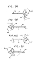
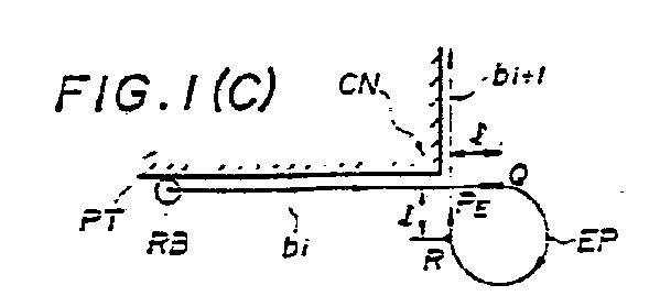
- Fig. 1 is a view for describing the general features of the present invention in a case where the inner side of a corner is part.
- RB represents a laser beam
- b i an offset path of an i-th block
- b i+l an offset path of an (i+l)th block
- EP a escape path
- CN a corner portion
- PT a part.
- the escape path EP will be composed of a line segment P EQ , a circular arc tangent to line segments P E Q, RP E at points Q, R, respectively, and the line segment RP E .
- Figs. 1(A) through (D) all relate to cases where the inner side of a corner is the part PT.
- Figs. 1(A), (B) are for cases where the offset direction is on the left side of the travelling direction and the curve at the corner portion is in the clockwise direction.
- Figs. l(C), (D) are for cases where the offset direction is on the right side of the travelling direction and the curve at the corner portion is in the counter-clockwise direction.
- the escape path EP inserted at the corner portion CN is preset, and a motion definition statement prepared without taking the escape path into consideration is inputted. It is determined whether the inner side of the beam path at the corner is the part PT based on the offset direction, which indicates whether a laser beam RB is offset in a direction to the right side or left side of the travelling direction contained in the motion definition statement, and the direction of the curve at the corner portion CN of the beam paths b i , b i+1 . If the inner side of the corner is the part PT, an NC part program is created upon inserting the preset escape path EP in the corner portion. Inserting the escape path EP renders the degree of change in velocity at the corner portion CN negligible in terms of machining precision, thus making highly precise laser machining possible.
- F ig. 2 is a view for describing the general features of the present invention in a case where the outer side of a corner is the part.
- RB represents the laser beam
- b i the offset path of the i-th block
- bi+1 the offset path of the (i+l)th block
- EP the escape path
- CN the corner portion
- PT the part
- P the end point of the i-th block
- QP PR machining condition modification intervals
- Figs. 2(A) through (D) all relate to cases where the outer side of a corner is the part PT.
- Figs. 2(A), (B) are for cases where the offset direction is on the right side of the travelling direction and the curve at the corner portion is in the clockwise direction.
- Figs. 2(C), (D) are for cases where the offset direction is on the left side of the travelling direction and the curve at the corner portion is in the counter-clockwise direction.
- the machining condition modification intervals QP, PR lengths l 1 , l 2 ) at the corner portion CN and the machining conditions (laser beam feed velocity and laser power value) in these intervals are preset, and a motion definition statement is prepared without taking these machining condition modification intervals and machining conditions into consideration.
- an NC part program it is determined whether the outer side of the beam path at the corner is the part PT based on the offset direction, which indicates whether the laser beam RB is offset in a direction to the right side or left side of the travelling direction contained in the motion definition statement, and the direction of the curve at the corner portion CN of the beam paths b i, b i+1 . If the outer side of the corner is the part PT, an NC part program is created in such a manner that the preset machining conditions prevail in the aforementioned machining condition modification intervals QP, PR.
- NC data are created for movement at predetermined machining conditions (machining conditions specified by the motion definition statement) up to the point Q
- NC data are created for movement at the set machining conditions from point Q to point P
- NC data are created for movement at similar set machining conditions from point P to point R.
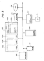
- Fig. 3 is a block diagram of an automatic programming apparatus according to an embodiment of the present invention.
- Numeral 101 denotes a ROM storing a loading program and the like, 102 a processor for executing automatic programming processing, and 103 a RAM.
- the RAM 103 has a storage area 103a for storing a system program STPR read in from a floppy disc, a storage area 103b for storing an NC data output table, a storage area 103c for storing a correlation FNT between function codes and ND data output formats, a storage area 103d for storing various parameters PRM, and a working area 103e.
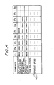
- the NC data output table NCDT stored in the storage area 103b has a plurality of function codes Fl - F9 specifying NC data output formats for each command, as shown in Fig. 4. Each function code is expressed by four hexadecimal digits. N C data having one execution format are specified by a set of several of these function codes.
- numeral 104 denotes an NC data memory for storing the NC data created, 105 a keyboard, 106 a display unit (CRT), 107 a disc controller, and FL a floppy disc.
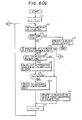
- Fig. 6 is a flowchart of processing according to the present invention
- Fig. 7 is a view for describing a corner radius which requires that machining conditions be modified
- Fig. 8 is a view for describing an angle of intersection which requires that machining conditions be modified. Processing according to the invention will now be described with reference to Figs. 1 through 8. It is assumed that the system program for creating an NC part program for laser machining, the NC data output table NCDT, the correlations FNT between the function codes and NC data output formats, and the parameters from the floppy disc have been stored in the storage areas 103a - 103d of the R AM 103.
- the parameters PRM include the escape path EP to be inserted at a corner, an angle B S serving as a criterion for deciding whether the escape path is to be inserted or not, the machining condition modification intervals QP, PR (see Fig. 2) at the corner portion, data specifying the machining conditions in these intervals, and an angle AS and radius R S serving as criteria for deciding whether the machining conditions are to be modified or not.
- the escape path EP will be composed of the line segment P EQ , the circular arc tangent to line segments P EQ , RP E at points Q, R, respectively, and the line segment RPE.
- the escape path is a path along which there is no change in cutting velocity at the corner portion. Accordingly, the escape path is not limited to that shown in Fig. 1.
- the machining condition modification intervals QP, PR for a case where the i-th block and (i+l)th block are straight lines (see Fig. 2) are specified by the distances l 1 , l 2 from the end point P of the i-th block, and the machining conditions are specified by feed velocities V 1 , V 2 and laser power values E 1 , E 2 of the laser beam.
- the (i+l)th block is a circular arc (see Fig.
- machining condition modification intervals QPl, F 2 R are specified by the distance l 1 from the end point (circular arc starting point) Pl of the i-th block and the distance l 2 from the end point (circular arc end point) of the (i+l)th block.
- the inner side of the corner is the part in a case where the offset direction of the laser beam is on the left side of the travelling direction and curves clockwise at the end point corner portion [see Figs. 1(A), (B)], and in a case where the offset direction of the laser beam is on the right side of the travelling direction and curves counter-clockwise at the end point corner portion [see Figs. l(C), (D)].
- the outer side of the corner is the part in a case where the offset direction of the laser beam is on the right side of the travelling direction and curves clockwise at the end point corner portion [see Figs. 2(A), (B)], and in a case where the offset direction of the laser beam is on the left side of the travelling direction and curves counter-clockwise at the end point corner portion [see Figs. 2(C), (D)].
- Processing is executed from step (6) onward if the inner side of the corner is the part, and from step (12) onward if the outer side of the corner is the part.
- the corner angle B is acute and relatively large, the change in velocity at the corner portion will not be great enough to influence machining precision. Therefore, in accordance with the present invention, if the corner angle B is larger than the preset angle (the minimum allowable angle that will have no influence upon machining precision) B S , an escape path is not inserted even though the inner side of the corner is the part.
- machining velocity does not change at the corner portion CN owing to insertion of the escape path EP is that pulses generated by a pulse distributing operation are not interrupted at the corner portion thanks to the insertion of the escape path.
- the escape path is not inserted. The reason for this is that it is assumed that the straight line of the i-th block and the circular arc of the (i+l)th block are tangent to each other.
- the straight line of the i-th block and the circular arc of the (i+l)th block are not tangent to each other, the point of intersection between the straight line and circular arc is obtained, a line tangent to the circular arc at the point of intersection is obtained, the angle of intersection B between this tangent line and the straight line is determined, and the escape path EP is inserted when the angle B is less than the predetermined angle B S .
- step (12) onward processing is executed from step (12) onward.
- NC data for movement up to point Q at the predetermined machining conditions are created, NC data for movement from point Q to point P 1 at machining conditions set together with l 1 are created, NC data for movement from point P I to point P 2 at machining conditions identical with those between Q and P 1 are created, and NC data for movement from point P 2 to point R at machining conditions set together with l 2 are created.
- the laser power value is set by an S code.
- corner angle A is acute and relatively large, the change in velocity at the corner portion will not be great enough to influence machining precision. Therefore, in accordance with the present invention, if the corner angle A is larger than a preset angle AS, machining conditions are not modified even though the outer side of the corner is the part.
- the machining velocity (laser beam feed velocity) and laser power value at the corner portion are set so that they will be smaller the machining velocity and laser power value which prevailed up to the corner portion.
- the case is one in which one machining condition modification interval is provided in each block.
- a plurality of machining condition modification intervals indicated by l 1 , l 2 , l 3 are provided in one block, with the settings being such that the machining velocity and laser power value in each interval gradually decrease and gradually increase.
- an escape path to be inserted at a corner portion is preset, and the arrangement is such that if the inner side of the corner is a part, an NC part program is created upon inserting the preset escape path at the corner portion.
- the feed velocity does not undergo a large change at the corner portion and, hence, any decline in machining precision at the corner portion can be suppressed.
- a laser machining NC part program in which machining precision at the corner portion can be maintained is capable of being created through a simple technique.
- a minimum allowable angle B S which does not influence machining precision at a corner portion is preset, and the arrangement is such that the escape path is inserted at the corner portion only if the actual corner angle B is less than BS and the inner side of the corner is the part.
- machining condition modification intervals at a corner portion and machining conditions are preset.
- the arrangement is such that if the outer side of the corner is the part, the set machining conditions are adopted as the machining conditions at the corner portion.
- the feed velocity and laser power are changed a predetermined distance short of the corner, and the original machining conditions are restored at a point a predetermined distance beyond the corner.
Landscapes
- Physics & Mathematics (AREA)
- Engineering & Computer Science (AREA)
- Geometry (AREA)
- Human Computer Interaction (AREA)
- Manufacturing & Machinery (AREA)
- General Physics & Mathematics (AREA)
- Automation & Control Theory (AREA)
- Numerical Control (AREA)
- Laser Beam Processing (AREA)
Abstract

Description
- This invention relates to a method of creating an NC part program for laser machining and, more particularly, to an NC part program creation method capable of improving machining precision at corners.
- In automatic programming for creating NC data using an automatic programming language such as APT or FAPT,
- {a) a part program based on the automatic programming language is created by defining points, straight lines and circular arcs using simple symbols (this is referred to as "figure definition"), and then defining a tool path using the defined points, straight lines and circular arcs (referred to as "motion statement definition"), and
- (b) the part program based on the automatic programming language is subsequently converted, by using an NC data output table, into NC data comprising NC data (EIA codes or ISO codes) in a format capable of being executed by an NC unit. It should be noted that the tools used include, in addition to ordinary tools, the wire in a wire-cut electrical discharge machine, the laser beam in a laser processing machine, etc.
- For example, in the creation of a part program for moving a tool (laser beam) along a profile comprising straight lines and circular arcs shown in Fig. 10, figure definition is performed by defining a tool starting point P1, cutting starting point P2, straight, lines S1, S2 and circular arc C1 ... as follows:








- In the foregoing, (1) instructs the start of the part program, with "REIDAI" being the header.
- (2) indicates the type of NC machine. "MILL". is used in case of milling, "TURN" in case of turning, "CUT" in case of a wire-cut electrical discharge machine, and "LASER" in case of laser machining. "ABS" indicates an absolute command. ("INCR" would be used for an incremental command.)
- (3) signifies a straight line passing through points P2. P3.
- (4) signifies a circular arc of center (x4,y4) and radius r1.
- (5) signifies a lower tangent line (straight line) of two tangent lines passing through point P5 and contacting the circular arc cl. In the case of the upper tangent line, the alphabetic character A would be used instead of B.
- (6) represents a beam command which commands a beam diameter of 0.3 mm.
- (7) represents a command indicating that the laser power is 800 W.
- (8) is a command for offsetting the tool to the left of the direction of movement. ("TLRGT" would be used to offset the tool to the right of the direction of movement.)
- (9) is a coordinate system setting command which indicates that the starting point is p1.
- (10) is a command for positioning the cutter in such a manner that the cutter will contact the straight line S1 at point P2 without passing this straight line.
- (11) is a velocity command indicating that the feed velocity is 500 mm/min.
- When a tool path includes a corner, the tool feed velocity in the vicinity of the corner generally cannot be held constant because of the characteristics of the machine, etc. For example, if an i-th block bi and an (i+1)th block bi+1 of the tool path intersect perpendicularly, as shown in Fig. 11, the tool feed velocity is as shown in Fig. 12. Thus, deceleration and acceleration are required when passing the corner portion. In other words, in the vicinity of the corner, the feed velocity along the X axis is reduced from the commanded velocity V and attains a value of zero, after which the feed velocity Vy along the Y axis is increased to reattain the commanded velocity Vc .
- This deceleration and acceleration of feed at the corner portion has a deleterious effect upon the machining precision of the part. In particular, altering the feed velocity has considerable influence upon machining precision in cases where a high machining velocity is required, as in laser machining.
- Though it is necessary that an NC part program be created in such a manner that the machining precision at the corner portion does not suffer, the fact is that NC part programs are created in the prior art without taking machining precision at corner portions into consideration.
- Accordingly, an object of the present invention is to provide a method of creating an NC part program for laser machining in which a decline in machining precision at corner portions can be suppressed.
- Another object of the present invention is to provide a method of creating an NC part program for laser machining in which machining precision at corner portions can be maintained through a simple technique.
- Still another object of the present invention is to provide a method of creating an NC part program in which, when a part has a corner portion on an inner side, machining precision at the corner portion can be improved by inserting a preset escape path at the corner portion.
- A further object of the present invention is to provide a method of creating an NC part program in which, when a part has a corner portion on an outer side, machining precision at the corner portion can be improved by changing the machining conditions at the corner portion from the machining conditions which prevailed up to the corner portion, such as by lowering feed velocity and laser power a predetermined distance short of the corner, and restoring the former machining conditions, after the corner is passed, at a point a predetermined distance beyond the corner.
- Based on an offset direction which indicates whether a laser beam is offset in a direction to the right side or left side of a travelling direction contained in a motion definition statement, and the direction of a curve at a corner portion of a laser beam path, it is determined whether an inner side or outer side of the beam path at the corner is a part. If the inner side of the corner is a part, an NC part program for laser machining is created upon inserting a preset escape path in the corner portion of the beam path. If the outer side of the corner is a part, an NC part program for laser machining is created in such a manner that similarly set machining conditions prevail in preset machining condition modification intervals.
-
- Fig. 1 is a view for describing the general features of the present invention in a case where the inner side of a corner is part;
- Fig. 2 is a view for describing the general features of the present invention in a case where the outer side of a corner is part;
- Fig. 3 is a block diagram of an automatic programming apparatus for practicing the present invention;
- Fig. 4 is a view for describing an NC data output table;
- Fig. 5 is a view showing the correlation between function codes and NC data output formats;
- Fig. 6 is a flowchart of processing according to the invention;
- Fig. 7 is a view for describing a corner radius which requires that machining conditions be modified;
- Fig. 8 is a view for describing an angle of intersection which requires that machining conditions be modified;
- Fig. 9 is a view for describing a case where a plurality of machining condition modification intervals are inserted at a corner;
- Fig. 10 is a view for describing automatic programming according to the prior art; and
- Figs. 11 and 12 are views for describing a disadvantage of the prior-art method.
- Fig. 1 is a view for describing the general features of the present invention in a case where the inner side of a corner is part. RB represents a laser beam, bi an offset path of an i-th block, bi+l an offset path of an (i+l)th block, EP a escape path, CN a corner portion, and PT a part. On the assumption that the point of intersection of the offset paths bit bi+1 of the i-th and (i+l)th blocks is PE, and that points located a distance l from the point of intersection PE in the direction of extensions of the offset paths are Q, R, the escape path EP will be composed of a line segment PEQ, a circular arc tangent to line segments PEQ, RPE at points Q, R, respectively, and the line segment RPE.
- Figs. 1(A) through (D) all relate to cases where the inner side of a corner is the part PT. Figs. 1(A), (B) are for cases where the offset direction is on the left side of the travelling direction and the curve at the corner portion is in the clockwise direction. Figs. l(C), (D) are for cases where the offset direction is on the right side of the travelling direction and the curve at the corner portion is in the counter-clockwise direction.
- The escape path EP inserted at the corner portion CN is preset, and a motion definition statement prepared without taking the escape path into consideration is inputted. It is determined whether the inner side of the beam path at the corner is the part PT based on the offset direction, which indicates whether a laser beam RB is offset in a direction to the right side or left side of the travelling direction contained in the motion definition statement, and the direction of the curve at the corner portion CN of the beam paths bi, bi+1. If the inner side of the corner is the part PT, an NC part program is created upon inserting the preset escape path EP in the corner portion. Inserting the escape path EP renders the degree of change in velocity at the corner portion CN negligible in terms of machining precision, thus making highly precise laser machining possible.
- Fig. 2 is a view for describing the general features of the present invention in a case where the outer side of a corner is the part. RB represents the laser beam, bi the offset path of the i-th block, bi+1 the offset path of the (i+l)th block, EP the escape path, CN the corner portion, PT the part, P the end point of the i-th block, and QP, PR machining condition modification intervals, the lengths where are l1, l2, respectively, from the end point P.
- Figs. 2(A) through (D) all relate to cases where the outer side of a corner is the part PT. Figs. 2(A), (B) are for cases where the offset direction is on the right side of the travelling direction and the curve at the corner portion is in the clockwise direction. Figs. 2(C), (D) are for cases where the offset direction is on the left side of the travelling direction and the curve at the corner portion is in the counter-clockwise direction.
- The machining condition modification intervals QP, PR (lengths l1, l2) at the corner portion CN and the machining conditions (laser beam feed velocity and laser power value) in these intervals are preset, and a motion definition statement is prepared without taking these machining condition modification intervals and machining conditions into consideration.
- In the creation of an NC part program, it is determined whether the outer side of the beam path at the corner is the part PT based on the offset direction, which indicates whether the laser beam RB is offset in a direction to the right side or left side of the travelling direction contained in the motion definition statement, and the direction of the curve at the corner portion CN of the beam paths b i, bi+1. If the outer side of the corner is the part PT, an NC part program is created in such a manner that the preset machining conditions prevail in the aforementioned machining condition modification intervals QP, PR.
- More specifically, NC data are created for movement at predetermined machining conditions (machining conditions specified by the motion definition statement) up to the point Q, NC data are created for movement at the set machining conditions from point Q to point P, and NC data are created for movement at similar set machining conditions from point P to point R.
- Fig. 3 is a block diagram of an automatic programming apparatus according to an embodiment of the present invention.
- Numeral 101 denotes a ROM storing a loading program and the like, 102 a processor for executing automatic programming processing, and 103 a RAM.
- The
RAM 103 has a storage area 103a for storing a system program STPR read in from a floppy disc, astorage area 103b for storing an NC data output table, astorage area 103c for storing a correlation FNT between function codes and ND data output formats, astorage area 103d for storing various parameters PRM, and a workingarea 103e. - The NC data output table NCDT stored in the
storage area 103b has a plurality of function codes Fl - F9 specifying NC data output formats for each command, as shown in Fig. 4. Each function code is expressed by four hexadecimal digits. NC data having one execution format are specified by a set of several of these function codes. - Some correlations between function codes stored in
storage area 103c and NC output formats are shown in Fig. 5. A coordinate system setting NC data output format in the NC data output table NCDT of Fig. 3 is - 8502, 0001, 0101, 0201, 0004
- 8202, 8002, 0001, 0101, 0201, 0141, 0004
- 8202, 8012, 0001, 0101, 0301, 0401, 0004
- Returning to Fig. 3, numeral 104 denotes an NC data memory for storing the NC data created, 105 a keyboard, 106 a display unit (CRT), 107 a disc controller, and FL a floppy disc.
- Fig. 6 is a flowchart of processing according to the present invention, Fig. 7 is a view for describing a corner radius which requires that machining conditions be modified, and Fig. 8 is a view for describing an angle of intersection which requires that machining conditions be modified. Processing according to the invention will now be described with reference to Figs. 1 through 8. It is assumed that the system program for creating an NC part program for laser machining, the NC data output table NCDT, the correlations FNT between the function codes and NC data output formats, and the parameters from the floppy disc have been stored in the storage areas 103a - 103d of the R
AM 103. Also it is assumed that the parameters PRM include the escape path EP to be inserted at a corner, an angle BS serving as a criterion for deciding whether the escape path is to be inserted or not, the machining condition modification intervals QP, PR (see Fig. 2) at the corner portion, data specifying the machining conditions in these intervals, and an angle AS and radius RS serving as criteria for deciding whether the machining conditions are to be modified or not. - On the assumption (see Fig. 1) that the point of intersection of the offset paths bi, bi+1 of the i-th and (i+l)th blocks is PEr and that points located a distance l from the point of intersection PE in the direction of extensions of the offset paths are Q, R, the escape path EP will be composed of the line segment PEQ, the circular arc tangent to line segments PEQ, RPE at points Q, R, respectively, and the line segment RPE. In other words, the escape path is a path along which there is no change in cutting velocity at the corner portion. Accordingly, the escape path is not limited to that shown in Fig. 1. The machining condition modification intervals QP, PR for a case where the i-th block and (i+l)th block are straight lines (see Fig. 2) are specified by the distances l1, l2 from the end point P of the i-th block, and the machining conditions are specified by feed velocities V1, V2 and laser power values E1, E2 of the laser beam. In a case where the (i+l)th block is a circular arc (see Fig. 7), machining condition modification intervals QPl, F2R are specified by the distance l1 from the end point (circular arc starting point) Pl of the i-th block and the distance l2 from the end point (circular arc end point) of the (i+l)th block.
- (1) First, when the figure definition statement and motion definition statement are created and inputted, the
processor 102 performs theoperation 1 → i. It should be noted that the escape path, machining condition modification intervals and machining conditions in these intervals are not taken into consideration in the motion definition statement. - (2) Next, the end point of the i-th block is computed from the figure definition statement and motion definition statement.
- (3) When the end point of the i-th block is obtained, a check is performed to determine whether this end point is the end point of the laser beam path.
- (4) If the end point is the end point of the path, then the i-th block of NC data is created using the coordinates of this end point and processing for creating the NC part program is ended.
- (5) If the end point is found not to be the end point of the path in step (3), then it is checked whether the inner side or outer side of the corner portion at the end point of the i-th block is the part.
- It should be noted that the inner side of the corner is the part in a case where the offset direction of the laser beam is on the left side of the travelling direction and curves clockwise at the end point corner portion [see Figs. 1(A), (B)], and in a case where the offset direction of the laser beam is on the right side of the travelling direction and curves counter-clockwise at the end point corner portion [see Figs. l(C), (D)]. Conversely, the outer side of the corner is the part in a case where the offset direction of the laser beam is on the right side of the travelling direction and curves clockwise at the end point corner portion [see Figs. 2(A), (B)], and in a case where the offset direction of the laser beam is on the left side of the travelling direction and curves counter-clockwise at the end point corner portion [see Figs. 2(C), (D)].
- Processing is executed from step (6) onward if the inner side of the corner is the part, and from step (12) onward if the outer side of the corner is the part.
- (6) If the inner side of the corner is the part, it is determined whether the (i+l)th block is a straight line.
- (7) If this block is a circular arc, the i-th block of NC data is created without inserting an escape path at the corner.
- (8) If the (i+l)th block is a straight line, the angle of intersection B between the i-th block and (i+l)th block is calculated.
- (9) Next, the angle B and a preset angle BS are compared in terms of magnitude.
- If the corner angle B is acute and relatively large, the change in velocity at the corner portion will not be great enough to influence machining precision. Therefore, in accordance with the present invention, if the corner angle B is larger than the preset angle (the minimum allowable angle that will have no influence upon machining precision) BS, an escape path is not inserted even though the inner side of the corner is the part.
- Accordingly, if B>BS holds, the i-th block of NC data is created at step (7) without inserting an escape path.
- (10) If B<BS holds, however, NC data are created in such a manner that the escape path EP that has been set in the parameter storage area is inserted after the i-th block.
- (11) Thereafter, i is incremented by the operation i + 1 → i and the processing from step (2) onward is repeated.
- It should be noted that the reason why machining velocity does not change at the corner portion CN owing to insertion of the escape path EP is that pulses generated by a pulse distributing operation are not interrupted at the corner portion thanks to the insertion of the escape path. Further, when the (i+l)th block is a circular arc at step (6), the escape path is not inserted. The reason for this is that it is assumed that the straight line of the i-th block and the circular arc of the (i+l)th block are tangent to each other. Accordingly, if the straight line of the i-th block and the circular arc of the (i+l)th block are not tangent to each other, the point of intersection between the straight line and circular arc is obtained, a line tangent to the circular arc at the point of intersection is obtained, the angle of intersection B between this tangent line and the straight line is determined, and the escape path EP is inserted when the angle B is less than the predetermined angle BS.
- The foregoing relates to a case where the inner side of a corner is the part. In an instance where the outer side of a corner is the part, processing is executed from step (12) onward.
- (12) If the outer side of the corner is the part, it is determined whether the (i+l)th block is a circular arc. If the radius of the corner arc is greater than a predetermined value, the change in the cutting velocity of the laser beam at the corner portion will not be great enough to influence machining precision. Therefore, in accordance with the present invention, if the corner arc radius R (see Fig. 7) is greater than a preset radius RS, the machining conditions are not modified even though the outer side of the corner is the part.
- (13) Accordingly, if the (i+l)th block is found to be a circular at step (12), the corner radius R is calculated; if not, the program jumps to step (18).
- (14) If the (i+l)th block is a circular arc and the corner arc radius R has been obtained, it is determined whether R<RS holds.
- (15) If R>RS holds, the i-th block (straight line block) and (i+l)th block (circular arc block) of NC data are created without modifying the machining conditions.
- (16) If R<RS holds, however, NC data are created in such a manner that the aforementioned set machining conditions prevail in machining condition modification intervals QP1, P1P2' P2R (see Fig. 7) specified by l1, l2 set in the
parameter storage area 103d. - More specifically, NC data for movement up to point Q at the predetermined machining conditions (machining conditions specified by the motion definition statement) are created, NC data for movement from point Q to point P1 at machining conditions set together with l1 are created, NC data for movement from point PI to point P2 at machining conditions identical with those between Q and P1 are created, and NC data for movement from point P2 to point R at machining conditions set together with l2 are created. The laser power value is set by an S code.
- (17) At the end of processing for steps (15) and (16), i is incremented by the operation i + 2 → i and processing from step (2) onward is subsequently repeated.
- (18) If the decision rendered at step (12) is that the (i+l)th block is a straight line, an angle of intersection A (see Fig.8) between the i-th block and (i+l)th block is calculated.
- (19) Next, the angle A and a preset angle AS are compared in terms of magnitude.
- If the corner angle A is acute and relatively large, the change in velocity at the corner portion will not be great enough to influence machining precision. Therefore, in accordance with the present invention, if the corner angle A is larger than a preset angle AS, machining conditions are not modified even though the outer side of the corner is the part.
- (20) Accordingly, if A>AS holds, the i-th block of NC data is created without modifying machining conditions.
- (21) If A<AS holds, however, NC data are created in such a manner that the aforementioned set machining conditions will prevail in machining condition modification intervals QP, PR (see Fig. 2) specified by l1' l2 set in the
parameter storage area 103d. More specifically, NC data for movement up to point Q at the predetermined machining conditions (machining conditions specified by the motion definition statement) are created, NC data for movement from point Q to point P at machining conditions set together with l1 are created, and NC data for movement from point P to point R at machining conditions set together with 12 are created. - (22) At the end of the processor for steps (20), (21), i is incremented by the operation i + 1 → i, after which processing is repeated from step (2) onward.
- It should be noted that the machining velocity (laser beam feed velocity) and laser power value at the corner portion are set so that they will be smaller the machining velocity and laser power value which prevailed up to the corner portion. In the foregoing, the case is one in which one machining condition modification interval is provided in each block. However, as shown in Fig. 9, it is possible to adopt an arrangement in which a plurality of machining condition modification intervals indicated by l1, l2, l3 are provided in one block, with the settings being such that the machining velocity and laser power value in each interval gradually decrease and gradually increase.
- Thus, in accordance with the present invention, an escape path to be inserted at a corner portion is preset, and the arrangement is such that if the inner side of the corner is a part, an NC part program is created upon inserting the preset escape path at the corner portion. As a result, the feed velocity does not undergo a large change at the corner portion and, hence, any decline in machining precision at the corner portion can be suppressed. Moreover, a laser machining NC part program in which machining precision at the corner portion can be maintained is capable of being created through a simple technique.
- Further, in accordance with the invention, a minimum allowable angle BS which does not influence machining precision at a corner portion is preset, and the arrangement is such that the escape path is inserted at the corner portion only if the actual corner angle B is less than BS and the inner side of the corner is the part. As a result, the number of corner portions requiring insertion of an escape path can be reduced to lessen the effect upon machining time.
- Further, in accordance with the invention, machining condition modification intervals at a corner portion and machining conditions are preset. The arrangement is such that if the outer side of the corner is the part, the set machining conditions are adopted as the machining conditions at the corner portion. For example, it can be so arranged that the feed velocity and laser power are changed a predetermined distance short of the corner, and the original machining conditions are restored at a point a predetermined distance beyond the corner. This makes it possible to create, through a simple technique, an NC part program in which a decline in machining precision at the corner portion can be suppressed.
Therefore, the NC data having the execution format for setting the coordinate system is

The NC data having the execution format for positioning/linear cutting is

The NC data having the execution format for circular arc cutting is

Claims (8)
Applications Claiming Priority (5)
| Application Number | Priority Date | Filing Date | Title |
|---|---|---|---|
| JP202984/86 | 1986-08-29 | ||
| JP61202983A JPH0677206B2 (en) | 1986-08-29 | 1986-08-29 | Method for creating NC part program for laser machining |
| JP61202984A JPS6358507A (en) | 1986-08-29 | 1986-08-29 | Nc part programming for laser beam machining |
| JP202983/86 | 1986-08-29 | ||
| PCT/JP1987/000626 WO1988001765A1 (en) | 1986-08-29 | 1987-08-26 | Method of preparing nc pert program for laser machining |
Publications (3)
| Publication Number | Publication Date |
|---|---|
| EP0282599A1 true EP0282599A1 (en) | 1988-09-21 |
| EP0282599A4 EP0282599A4 (en) | 1991-03-13 |
| EP0282599B1 EP0282599B1 (en) | 1994-12-14 |
Family
ID=26513681
Family Applications (1)
| Application Number | Title | Priority Date | Filing Date |
|---|---|---|---|
| EP87905642A Expired - Lifetime EP0282599B1 (en) | 1986-08-29 | 1987-08-26 | Method of preparing nc part program for laser machining |
Country Status (4)
| Country | Link |
|---|---|
| US (1) | US4870560A (en) |
| EP (1) | EP0282599B1 (en) |
| DE (1) | DE3750873T2 (en) |
| WO (1) | WO1988001765A1 (en) |
Cited By (6)
| Publication number | Priority date | Publication date | Assignee | Title |
|---|---|---|---|---|
| GB2237127A (en) * | 1989-08-08 | 1991-04-24 | Amada Wasino Co | Method for machining a corner section in a workpiece by means of NC electro-discharge machining apparatus |
| EP0477408A1 (en) * | 1990-09-27 | 1992-04-01 | Siemens Aktiengesellschaft | Method for the machining of workpieces with a numerically controlled machine |
| WO1995010077A1 (en) * | 1993-10-06 | 1995-04-13 | Electro Scientific Industries, Inc. | Radiation beam position and emission coordination system |
| EP1369197A2 (en) | 2002-06-03 | 2003-12-10 | Yamazaki Mazak Kabushiki Kaisha | Laser beam machine |
| WO2004070483A1 (en) * | 2003-01-29 | 2004-08-19 | Open Mind Software Technologies Gmbh | Method for controlling relative displacements of a tool against a workpiece |
| WO2020225174A1 (en) | 2019-05-09 | 2020-11-12 | Dürr Systems Ag | Coating method and corresponding coating installation |
Families Citing this family (9)
| Publication number | Priority date | Publication date | Assignee | Title |
|---|---|---|---|---|
| JP2564564B2 (en) * | 1987-09-10 | 1996-12-18 | ファナック 株式会社 | Laser processing equipment |
| JP2542653B2 (en) * | 1987-12-10 | 1996-10-09 | ファナック株式会社 | Non-contact copying method |
| JPH01282609A (en) * | 1988-05-10 | 1989-11-14 | Fanuc Ltd | Method for setting nc data output form |
| JP2554750B2 (en) * | 1989-09-19 | 1996-11-13 | ファナック株式会社 | Laser processing method |
| JPH04111006A (en) * | 1990-08-30 | 1992-04-13 | Kobe Steel Ltd | Path interpolating method for robot |
| JP3387990B2 (en) * | 1993-11-09 | 2003-03-17 | ファナック株式会社 | Laser processing equipment |
| US5856649A (en) * | 1994-02-25 | 1999-01-05 | Fanuc Ltd. | Laser beam machine |
| DE112014001862B4 (en) * | 2013-08-07 | 2018-05-30 | Mitsubishi Electric Corporation | NC program generation device and NC program generation method |
| CN116197550A (en) * | 2023-03-01 | 2023-06-02 | 英诺威讯智能科技(杭州)有限公司 | Annular cutting method, device, equipment and storage medium in numerical control system |
Family Cites Families (9)
| Publication number | Priority date | Publication date | Assignee | Title |
|---|---|---|---|---|
| US3866179A (en) * | 1972-09-22 | 1975-02-11 | Giddings & Lewis | Numerical control with envelope offset and automatic path segment transitions |
| JPS55110307A (en) * | 1979-02-16 | 1980-08-25 | Oki Electric Ind Co Ltd | Correcting method for cutter diameter |
| JPS57114329A (en) * | 1980-12-30 | 1982-07-16 | Fanuc Ltd | Control of wire-cut electric discharge processor |
| IT1148370B (en) * | 1981-07-17 | 1986-12-03 | Fuji Tool & Die | THREE-DIMENSIONAL LASER CUTTING SYSTEM WITH THE REPRODUCTION METHOD |
| JPS59123008A (en) * | 1982-12-29 | 1984-07-16 | Fanuc Ltd | Forming method of part program |
| GB2136332B (en) * | 1983-01-21 | 1986-09-03 | Protocol Eng Ltd | Improvements in or relating to computer controlled tools for the production of graphic material for use in colour printing or like processes |
| US4782438A (en) * | 1986-06-10 | 1988-11-01 | Yamazaki Mazak Corporation | Means and method for translating a turret punch press control program into a laser beam machine control program |
| JPH05325779A (en) * | 1992-05-21 | 1993-12-10 | Fuji Photo Film Co Ltd | Method for manufacturing flash discharge tube |
| JP3087794B2 (en) * | 1992-06-05 | 2000-09-11 | ワイケイケイ株式会社 | Opening / closing control device for shutter with slit |
-
1987
- 1987-08-26 US US07/196,220 patent/US4870560A/en not_active Expired - Fee Related
- 1987-08-26 DE DE3750873T patent/DE3750873T2/en not_active Expired - Fee Related
- 1987-08-26 WO PCT/JP1987/000626 patent/WO1988001765A1/en not_active Ceased
- 1987-08-26 EP EP87905642A patent/EP0282599B1/en not_active Expired - Lifetime
Cited By (11)
| Publication number | Priority date | Publication date | Assignee | Title |
|---|---|---|---|---|
| GB2237127A (en) * | 1989-08-08 | 1991-04-24 | Amada Wasino Co | Method for machining a corner section in a workpiece by means of NC electro-discharge machining apparatus |
| EP0477408A1 (en) * | 1990-09-27 | 1992-04-01 | Siemens Aktiengesellschaft | Method for the machining of workpieces with a numerically controlled machine |
| WO1995010077A1 (en) * | 1993-10-06 | 1995-04-13 | Electro Scientific Industries, Inc. | Radiation beam position and emission coordination system |
| US5453594A (en) * | 1993-10-06 | 1995-09-26 | Electro Scientific Industries, Inc. | Radiation beam position and emission coordination system |
| EP1369197A2 (en) | 2002-06-03 | 2003-12-10 | Yamazaki Mazak Kabushiki Kaisha | Laser beam machine |
| EP1369197A3 (en) * | 2002-06-03 | 2007-06-13 | Yamazaki Mazak Kabushiki Kaisha | Laser beam machine |
| WO2004070483A1 (en) * | 2003-01-29 | 2004-08-19 | Open Mind Software Technologies Gmbh | Method for controlling relative displacements of a tool against a workpiece |
| WO2020225174A1 (en) | 2019-05-09 | 2020-11-12 | Dürr Systems Ag | Coating method and corresponding coating installation |
| DE102019112113A1 (en) * | 2019-05-09 | 2020-11-12 | Dürr Systems Ag | Coating process and corresponding coating system |
| US11904334B2 (en) | 2019-05-09 | 2024-02-20 | Dürr Systems Ag | Coating method and corresponding coating installation |
| US12263495B2 (en) | 2019-05-09 | 2025-04-01 | Dürr Systems Ag | Coating method and corresponding coating installation |
Also Published As
| Publication number | Publication date |
|---|---|
| DE3750873D1 (en) | 1995-01-26 |
| DE3750873T2 (en) | 1995-05-24 |
| US4870560A (en) | 1989-09-26 |
| EP0282599B1 (en) | 1994-12-14 |
| EP0282599A4 (en) | 1991-03-13 |
| WO1988001765A1 (en) | 1988-03-10 |
Similar Documents
| Publication | Publication Date | Title |
|---|---|---|
| US4914599A (en) | Method of creating NC part program laser machining | |
| EP0282599A1 (en) | Method of preparing nc part program for laser machining | |
| EP0160097B1 (en) | Area machining method | |
| EP0270679A1 (en) | Method of converting nc data | |
| US4939635A (en) | Automatic programming system | |
| US4704687A (en) | Method for constructioning tool approach and retraction paths from preset patterns | |
| EP0144426B1 (en) | Method of checking tool interference | |
| EP0175792B1 (en) | Area machining method | |
| US4905158A (en) | Normal vector computation method | |
| EP0166000A1 (en) | Area machining method | |
| EP0240569A1 (en) | Method of forming compposite curved surface | |
| EP0215955A1 (en) | Method of generating compound curved planes | |
| EP0423342B1 (en) | Interpolation method in automatic programming | |
| EP0235293A1 (en) | Method of producing compound curved surfaces | |
| EP0364600A1 (en) | Round screw machining method | |
| EP0436733A1 (en) | Involute interpolation error correction system | |
| EP0229851A1 (en) | Region machining method | |
| US4764877A (en) | Surface cutting method | |
| EP0237578A1 (en) | Method of forming composite curved surface | |
| EP0547244A1 (en) | Method for specifying position where fillet curved surface is located | |
| JPH0677206B2 (en) | Method for creating NC part program for laser machining | |
| EP0336975A1 (en) | Method of preparing nc data | |
| US4764878A (en) | Surface cutting method | |
| JPH0825145A (en) | Machining method in wire cut electric discharge machine | |
| EP0357791B1 (en) | Nc statement preparation system |
Legal Events
| Date | Code | Title | Description |
|---|---|---|---|
| PUAI | Public reference made under article 153(3) epc to a published international application that has entered the european phase |
Free format text: ORIGINAL CODE: 0009012 |
|
| 17P | Request for examination filed |
Effective date: 19880518 |
|
| AK | Designated contracting states |
Kind code of ref document: A1 Designated state(s): DE FR GB IT |
|
| A4 | Supplementary search report drawn up and despatched |
Effective date: 19910122 |
|
| AK | Designated contracting states |
Kind code of ref document: A4 Designated state(s): DE FR GB IT |
|
| RHK1 | Main classification (correction) |
Ipc: G05B 19/405 |
|
| 17Q | First examination report despatched |
Effective date: 19930416 |
|
| GRAA | (expected) grant |
Free format text: ORIGINAL CODE: 0009210 |
|
| AK | Designated contracting states |
Kind code of ref document: B1 Designated state(s): DE FR GB IT |
|
| PG25 | Lapsed in a contracting state [announced via postgrant information from national office to epo] |
Ref country code: FR Effective date: 19941214 |
|
| REF | Corresponds to: |
Ref document number: 3750873 Country of ref document: DE Date of ref document: 19950126 |
|
| ITF | It: translation for a ep patent filed | ||
| EN | Fr: translation not filed | ||
| PG25 | Lapsed in a contracting state [announced via postgrant information from national office to epo] |
Ref country code: GB Effective date: 19950826 |
|
| PLBE | No opposition filed within time limit |
Free format text: ORIGINAL CODE: 0009261 |
|
| STAA | Information on the status of an ep patent application or granted ep patent |
Free format text: STATUS: NO OPPOSITION FILED WITHIN TIME LIMIT |
|
| 26N | No opposition filed | ||
| GBPC | Gb: european patent ceased through non-payment of renewal fee |
Effective date: 19950826 |
|
| PGFP | Annual fee paid to national office [announced via postgrant information from national office to epo] |
Ref country code: DE Payment date: 19960830 Year of fee payment: 10 |
|
| PG25 | Lapsed in a contracting state [announced via postgrant information from national office to epo] |
Ref country code: DE Free format text: LAPSE BECAUSE OF NON-PAYMENT OF DUE FEES Effective date: 19980501 |
|
| PG25 | Lapsed in a contracting state [announced via postgrant information from national office to epo] |
Ref country code: IT Free format text: LAPSE BECAUSE OF NON-PAYMENT OF DUE FEES;WARNING: LAPSES OF ITALIAN PATENTS WITH EFFECTIVE DATE BEFORE 2007 MAY HAVE OCCURRED AT ANY TIME BEFORE 2007. THE CORRECT EFFECTIVE DATE MAY BE DIFFERENT FROM THE ONE RECORDED. Effective date: 20050826 |