EP0283167A2 - Audio-Digital-/Analog-Codierer und Decodierer - Google Patents
Audio-Digital-/Analog-Codierer und Decodierer Download PDFInfo
- Publication number
- EP0283167A2 EP0283167A2 EP88301836A EP88301836A EP0283167A2 EP 0283167 A2 EP0283167 A2 EP 0283167A2 EP 88301836 A EP88301836 A EP 88301836A EP 88301836 A EP88301836 A EP 88301836A EP 0283167 A2 EP0283167 A2 EP 0283167A2
- Authority
- EP
- European Patent Office
- Prior art keywords
- digital
- analog
- analog signal
- linear
- signal
- Prior art date
- Legal status (The legal status is an assumption and is not a legal conclusion. Google has not performed a legal analysis and makes no representation as to the accuracy of the status listed.)
- Withdrawn
Links
Images


Classifications
-
- H—ELECTRICITY
- H03—ELECTRONIC CIRCUITRY
- H03M—CODING; DECODING; CODE CONVERSION IN GENERAL
- H03M1/00—Analogue/digital conversion; Digital/analogue conversion
- H03M1/12—Analogue/digital converters
- H03M1/20—Increasing resolution using an n bit system to obtain n + m bits
- H03M1/208—Increasing resolution using an n bit system to obtain n + m bits by prediction
-
- H—ELECTRICITY
- H04—ELECTRIC COMMUNICATION TECHNIQUE
- H04B—TRANSMISSION
- H04B14/00—Transmission systems not characterised by the medium used for transmission
- H04B14/02—Transmission systems not characterised by the medium used for transmission characterised by the use of pulse modulation
- H04B14/04—Transmission systems not characterised by the medium used for transmission characterised by the use of pulse modulation using pulse code modulation
- H04B14/046—Systems or methods for reducing noise or bandwidth
Definitions
- the present invention relates to a method and associated apparatus for encoding an analog signal into a digital form and for decoding the digital signal back into an analog form, wherein the encoding and decoding are performed in such a way as to maximize the useful dynamic range of the signal when used for encoding and decoding an audio signal.
- Digital encoding of analog signals is usually accomplished by what is called a "linear" conversion, in which a simple direct binary value equal to the analog value to be encoded is generated. For example, an 8 bit digital system would encode all input analog signal values into one of 256 values linearly related to the input analog value. The conversion of the input analog signal into its binary representations takes place at a rate equal to at least twice the rate of the highest frequency component to be encoded within the analog signal. Because of the finite and limited number of representations possible using a binary number, the input signal is "quantized” and the representation at each sample may not accurately correspond to the associated analog value.
- the encoding system is an 8 bit system, there are only 256 values possible, i.e. 0 through 255; or, more specifically in binary representation, 00000000 through 11111111.
- the input analog value sampled were 128.438, for example, it would be represented by the nearest binary value, e.g. 1000000 or 128.
- the difference of .438 is an error often referred to as the "quantization error” or "quantization noise".
- the analog signal being converted is an audio signal, this error is heard as noise when the signal is decoded back into its analog form.
- the analog signal is large, the error represents only a small fraction of the overall signal value. When the signal is small, however, the error becomes much more significant. In fact, signals smaller than the quantization size are lost entirely.
- encoding/decoding apparatus performing the method of the present invention which comprises the steps of pre-emphasizing the analog signal to accentuate its high frequency components; successively sampling the pre-emphasized signal; encoding the samples non-linearly to create a series of digital representations of the samples having a lower order resolution than the sample resolution; obtaining the differences between the samples and their corresponding lower resolution digital representations; and combining each sample prior to encoding with the difference measurement for the previous sample.
- the encoded signal is then decoded in a non-linear complementary manner and converted to analog format to create an approximate analog output signal. This is followed by a deemphasis step which is complementary to the pre-emphasis to produce an analog output signal closely approximating the original analog input signal.
- both fully digital and hybrid analog/digital implementations of the present invention are possible and are disclosed with possible variations.
- the samples are converted to a digital format having a higher resolution than the series of digital representations.
- the digital representations are obtained from the digitally formatted samples, and the difference measurements are combined with the samples in their digital format.
- the difference measurement is combined with the pre-emphasized analog signal prior to sampling, and the samples are obtained from the combined analog signal and difference measurements.
- the present invention accomplishes its objectives by using a non-linear encoding method with an error carryback technique and high frequency pre-emphasis of the analog signal before encoding.
- the analog signal to be encoded digitally is first pre-emphasized; that is, the high frequencies are selectively accentuated.
- the signal is then encoded into digital form in a non-linear analog to digital (A-D) encoder.
- the non-linearity may be provided by either analog or digital means.
- the difference between the analog equivalent of the resultant non-linear digital representation and the input analog signal is measured and added to the next sampled analog value to be encoded.
- the digital representation is applied to a non-linear decoder which is complementary to the non-linear encoder used in the encoding processes. Again, this non-linear characteristic may be accomplished either digitally or by analog means.
- the signal is passed through a de-emphasis circuit which is complementary to the pre-emphasis circuit used in the encoding process.
- the hybrid encoder is shown in Figure 1.
- the input analog signal is applied to the pre-emphasis circuit 11 which emphasizes the high frequencies in the signal.
- the pre-emphasized signal is passed to the analog adder circuit 12, where the residual quantization error from the previous encoded sample is added to it.
- Sample and hold circuit 20 samples and holds the result and passes it on the sample and hold circuit 13. Two sample and hold circuits are necessary to prevent the resultant sum from adder 12 from immediately effecting itself instead of the subsequent sample.
- the sampled and held signal is applied to the input of the standard linear analog to digital converter 15 through the non-linear circuit 14.
- the output of A-D converter 15 is the digitally encoded output of the system.
- This digital signal also is passed to the linear digital to analog circuit 18 whose output passes to the non-linear circuit 17.
- non-linear circuit 17 The functions of non-linear circuit 17 are selected to be exactly complementary to the functions of the non-linear circuit 14. The result is that the output of non-linear circuit 17 is the quantized analog representation of the input analog signal. This signal is subtracted from the input signal by the difference circuit 16 and the resultant signal added to the next analog signal value to be sampled by the adder circuit 12. Note that D-A circuit 18 may be the D-A circuit within the A-D circuit 15.
- the anti-aliasing filter 19 limits the upper frequency limit of the input analog signal to one-half the sample rate of the digital encoder as is standard in digital encoding systems.
- the hybrid decoder is shown in Figure 2.
- the digital signal from the encoder is converted to an analog signal by the linear digital to analog converter 21 and passed through the non-linear circuit 24 which is identical to the non-linear circuit 17 of Figure 1. It is complementary in functions to non-linear circuit 14 in Figure 1.
- the output on the non-linear circuit is passed to post filter circuit 23 and then to de-emphasis circuit 22.
- De-emphasis circuit 22 de-emphasizes high frequency in a fashion complementary to the pre-emphasis of pre-emphasis circuit 11 in the encoder of Figure 1.
- Post filter 23 is similar to anti-aliasing filter 19 of the encoder.
- the input analog signal is frequency limited by anti-aliasing filter 31. As usual, this filter restricts the upper frequency limit of the input analog signal to less than one half the sample frequency of the A-D conversion part of the system.
- Pre-emphasis filter 32 selectively amplifies high frequencies as was the case in the hybrid encoder of Figure 1.
- the pre-emphasis filters should be adaptive. That is, it should adjust the amount of pre-emphasis of high frequencies in response to the amount of high frequency signal present. The greater the amplitude of the high frequency components, the more the high frequency boost is reduced.
- pre-emphasis filter 32 may be a single pole, i.e. 6 db/octave, filter designed with the slope up beginning between 200 and 1 KHz and leveling off in a shelf between 4 KHz and 10 KHz as shown in Figure 5. A fuller explanation of the reason for this filter will follow later herein.
- Circuit 33 holds the sampled analog value while the A-D converter circuit 34 converts it to a linear digital representation.
- the A-D converter 34 is a high resolution converter.
- converter 34 may be a 16 bit converter even though the final output digital signal of the system is 8 bits.
- Circuit 35 is a digital adder where the high resolution digital representation of the analog signal is added to the residue or difference between the 8 bit non-linear representation sent out as the output digital signal and the exact value of the previous sample.
- Circuit 36 which is designated as the non-linear encoder difference generator is, in the preferred embodiment, implemented as a dual look up table or memory.
- the high resolution i.e.
- circuit 36 can best be described and under stood with reference to the 8 to 4 bit encoder example shown in Table 1.
- Table 1 shows in column 1 some sign-magnified decimal values of an 8 bit linear representation of an analog signal ranging from +128 to -128. The next column gives the 4 bit non-linear decimal representation of these values.
- the encoding is simple for the values +/-1 and +/-2. They are encoded to their same value, i.e. +/-1 and +/-2. 8 bit values greater than or equal to 2 and less than 4 are also encoded to the 4 bit non-linear representation 2.
- the linear value 3 would be represented by the non-linear value 2 with a residue of 1.
- the linear 8 bit value of 23 would be represented by the nearest 4 bit non-linear representation 5, which equals 16 with a residue of 7.
- This encoding is a quasi-logarithmic encoding and is useful for encoding audio signals using this method because it takes advantage of the psychoacoustic phenomenon known as masking. Louder signals can mask or conceal larger errors or noise. Note that with this encoding method the encoding errors or residues tend to be proportional to the signal value.
- the full digital decoder for the full digital encoder shown in FIG. 3 is shown in FIG. 4.
- the low resolution, non-linear digital signal is applied to a memory 41 as the address in a manner similar to that used in the encoder circuit 36.
- the output of the memory is a high resolution digital representation applied to the high resolution decoder 42.
- the encoded signal may be an 8 bit non-linear representation.
- the memory 41 would have 256 locations, each with a 16 bit word stored therein. That 16 bit would be the linear 16 bit representation of the 8 bit non-linear value used as its address.
- This 16 bit linear digital value is then converted into the analog signal by the 16 bit linear D-A converter 42.
- Post filter 43 then removes all signal components outside the desired signal spectrum.
- De-emphasis circuit 44 is complementary to the pre-emphasis circuit 32 in the encoder shown in Figure 3.
- the general example discussed above involved using the present invention to encode a 16 bit linear digital representation into an 8 bit form and subsequently decode it back into a 16 bit digital form and then to an analog form.
- the specific example of Table 1 was for an 8 bit linear representation encoded into a 4 bit form.
- the method of the present invention can generally be applied to encoding any higher resolution digital representation of an analog signal into a low resolution non-linear form and recovering it. It is particularly applicable to audio signals where noise and errors proportional to signal size are more tolerable.
- Table 2 illustrates the fully digital encoding and decoding implementation of the present invention as employed with the 8 bit to 4 bit example previously discussed with relation to Table 1.
- Row 1 of Table 2 gives a series of 8 bit linear values to be encoded using the present invention.
- Row 2 is the sum of that value plus the residue left from the previous encoding quantization.
- Row 3 is the 4 bit non-linear representation of the sum.
- Row 4 is the residue or difference between the linear value associated with the 4 bit representation and the actual sum it is representing.
- Row 5 is the decoded, linear representation of the 4 bit non-linear representation.
- Row 6 is the resultant error.
- the content of the encoding and decoding memories 36 and 41 should be evident from this illustration.
- non-linear encoding may be used in particular situations; but, in all instances, the digital output of 36 will be a reduced number of bits compared to its input and each of those non-linear representations will map back into specific higher resolution input values.
- the linear residue output 37 of the difference generator 36 is equal to the digital difference between that linear input value and the non-linear representation value decoded back to linear form.
- the hybrid and fully digital forms of the present invention can be used together -- often to good advantage.
- a fully digital implementation of the encoder may be used with a hybrid implementation of the decoder.
- the non-linear function 24 shown in the hybrid decoder of Figure 2 would be mapped into the digital memory 36 used in the fully digital encoder of Figure 3.
- a hybrid non-linear circuit is often desirable because of its simplicity and reduced cost in the decoder.
- An example of a non-linear circuit usable in a decoder is shown in Figure 6.
- Diodes 62 and 63 are the non-linear elements. With resistor 61 small and resistors 64 and 67 large, the system becomes essentially an exponential decoder.
- diodes 62 and 63 are conventional semi-conductor diodes with an exponential current to voltage relationship.
- Resistor 61 sets the maximum slope or gain of the encoder while resistor 64 sets the minimum slope or gain.
- Resistor 65 sets the overall gain of the decoder circuit while 66 indicates a conventional operational amplifier.
- Resistor 67 acts with resistor 61 to form a voltage divider to reduce the input signal levels and impedances to the 1/2 volt range usable with typical diode non-linear elements.
- the non-linear decoder circuit shown in Figure 7 is complementary to the circuit of Figure 6.
- Resistor 72 should equal 64
- 73 should equal 61
- 71 should equal 65
- 67 should equal 72.
- the remaining components 74-77 are also of similar designation. It should be noted that the circuit shown in Figure 6 could be used as circuit 17 of Figure 1.
- a special case of the present invention is one in which the error residue carried back is set at zero.
- the benefit of reduced low frequency noise reduction is lost in this case but one gains the benefit of simplicity in the encoder.
- the same decoder is usable.
- the carryback technique may be used; but, it may be dispensed with in less critical applications and yet remain compatible with the same playback decoder.
- a simple approach to this problem is to have a pre-circuit which passes only the difference between the current sample and the previous sample. This is a differentiating or differentiator circuit.
- the pre-emphasis circuit described previously herein is a form of differentiator. It is modified at very high and very low frequencies to make its effect less radical.
- predictor circuits as known in the art can be used to great advantage as part of the present invention.
- a generally useful class of such predictors is one based on the derivatives of the input signal.
- FIG. 8 The use of a general predictor with the present invention's hybrid encoder is shown in Figure 8.
- the input analog signal is added to the residue error carryback in adder circuit 81.
- Sample and hold circuit 82 samples and hold the current value of the analog signal.
- Predictor 83 outputs its prediction of the current value based on the previous sampled values as described above.
- Difference circuit 84 outputs the difference between the actual current value and the predictor's prediction to the non-linear circuit 85.
- 86 is a linear A-D converter whose output is the non-linear encoded predictor differenced digital signal. This signal is converted back into the quantized linear for of the difference signal by; D-A converter 87 and non-linear circuit 88.
- This difference is added to the predictor signal from predictor 810 by adder circuit 89 to output a replica of the original signal to difference circuit 811.
- the output of circuit 811 is the difference between this reconstructed quantized signal and the correct original signal which is carried back and added to the next sample by adder 81.
- a hybrid decoder according to the present invention and employing a predictor is shown in Figure 9.
- the input digital signal from the encoder is converted to analog form by linear D-A converter 91.
- This signal is passed through the non-linear circuit 92 to adder circuit 93 where it is added to the predictor 94 output resulting in the output analog signal.
- predictors 83, 810 and 94 are identical in operation. These predictors must be stable; that is, not susceptible to oscillation or lockup and must converge. These requirements and how to attain them are well known to those skilled in the art and, therefore, in the interest of simplicity, will not be addressed further herein.
- the input analog signal is converted to a high resolution linear digital form by A-D converter 101 (which can be the A-D converter 21 of Figure 2).
- A-D converter 101 which can be the A-D converter 21 of Figure 2.
- the exact functions defined in Figure 8 are then all performed digitally by the digital processor 102.
- a standard microprocessor can be used for this function.
- a digital processor 111 performs the predictor functions, summing functions, and table lookups described previously for the digital implementation of the decoder and passes on the high resolution digital representations to the linear D-A converter 112 for conversion to the sampled output analog signal.
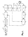
- FIG. 12 is a more detailed block diagram of the digital encoder/decoder system. Elements which are the same as in previous drawings are identified by the same reference numerals.
- Analog-digital encoder 34 converts the input analog samples into 16 bit digital representations.
- Adder 35 is a 16 ⁇ 16 device adapted to produce a 16 bit sum output from two 16 bit inputs. The output of adder 35 is delivered to an address register 39, which loads the word and provides a one-word delay for the signal subsequently fed back to adder 35.
- the address register 39 outputs a 16 bit address signal to a lookup table 37, which stores 8 bit words corresponding to each of the 65,536 possible 16 bit inputs.
- Lookup table 37 which may be implemented as a ROM, provides an 8 bit output which most closely approximates the 16 bit input. Since the resolution of the 16 bit words is 256 times that of the 8 bit output words, lookup table 37 provides the same 8 bit word for each set of 256 successive 16 bit input words (except for the first and last 8 bit words, which each have 128 corresponding 16 bit inputs).
- the 8 bit output digital signal from lookup table 37 is transmitted to the receiver, where it is delivered as an address to the non-linear memory 41 in the form of a decoder lookup table.
- This lookup table stores 256 16 bit words, and converts the 8 bit input signals to 16 bit output signals for application to digital-to-analog converter 42.
- Decoder lookup table 41 is generally complementary to encoder lookup table 37.
- the 16 bit output from decoder lookup table 41 will generally not be exactly the same as the 16 bit input to encoder lookup table 37 because the decoder lookup table only receives 8 bit input information, and therefore has no way of knowing the precise 16 bit signal at the input to encoder lookup table 37.
- the 16 bit output from decoder lookup table 41 is arbitrarily selected from one of the 256 possible outputs corresponding to each 8 bit input; in the preferred embodiment the 16 bit words placed in the lookup table 41 are selected to be the midpoints of each successive set of 256 16 bit words.
- lookup table 41 skips 255 possible words between each 16 bit word that is actually stored. In this way only one 16 bit word in the table will correspond to each of the possible 8 bit input signals.
- an 8 bit output signal will be produced by encoder lookup table 37, while the predicted error between the 16 bit input and the corresponding 16 bit output from decoder lookup table 41 is produced by error lookup table 38.
- This predicted error the production of which is delayed by a one word interval by address register 39, is fed back to adder 35, where it is added to the next 16 bit input sample.
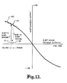
- FIG. 13 This arrangement is illustrated graphically in FIG. 13.
- the 16 bit outputs of adder 35 and decoder lookup table 41 are plotted along the horizontal axis, while the 8 bit output from en coder lookup table 37 is plotted along the vertical axis.
- the described system encompasses a total of 65,536 different 16 bit words, and 256 different 8 bit words. Each 8 bit word corresponds to 256 successive 16 bit words, as illustrated by the exaggerated step function 120.
- the encoding and decoding transformations are non-linear but symmetric about the origin.
- a 16 bit input 121 addresses lookup table 37.
- the lookup table will produce a corresponding 8 bit encoded output signal 122.
- decoder lookup table 41 does not know which of the 256 different possible 16 bit inputs produced the particular 8 bit output, it arbitrarily selects the median 16 bit word 123 within this range as its output.
- the difference (error) between this midpoint 123 and the actual 16 bit input 121 is indicated in FIG. 13 and is delivered from error lookup table 38 to modify the next 16 bit input to adder 35.
- EPROMs are used as the memory elements. These devices are quite expensive, and collectively can represent the major cost of the system.
- the described transformation from 16 bits down to 8 bits, and then back again to 16 bits, halves the number of EPROMs required as compared with a full 16 bit system, and also allows the capacity of the transmission system to be halved.
Landscapes
- Engineering & Computer Science (AREA)
- Theoretical Computer Science (AREA)
- Computer Networks & Wireless Communication (AREA)
- Signal Processing (AREA)
- Analogue/Digital Conversion (AREA)
- Compression, Expansion, Code Conversion, And Decoders (AREA)
Applications Claiming Priority (2)
| Application Number | Priority Date | Filing Date | Title |
|---|---|---|---|
| US07/027,747 US4862168A (en) | 1987-03-19 | 1987-03-19 | Audio digital/analog encoding and decoding |
| US27747 | 1993-03-05 |
Publications (2)
| Publication Number | Publication Date |
|---|---|
| EP0283167A2 true EP0283167A2 (de) | 1988-09-21 |
| EP0283167A3 EP0283167A3 (de) | 1991-06-05 |
Family
ID=21839554
Family Applications (1)
| Application Number | Title | Priority Date | Filing Date |
|---|---|---|---|
| EP19880301836 Withdrawn EP0283167A3 (de) | 1987-03-19 | 1988-03-02 | Audio-Digital-/Analog-Codierer und Decodierer |
Country Status (3)
| Country | Link |
|---|---|
| US (1) | US4862168A (de) |
| EP (1) | EP0283167A3 (de) |
| JP (1) | JPS63254825A (de) |
Cited By (2)
| Publication number | Priority date | Publication date | Assignee | Title |
|---|---|---|---|---|
| WO1995031049A1 (en) * | 1994-05-09 | 1995-11-16 | Linkplus Corporation | Companding system (lincompex) using pre- and de-emphasis |
| GB2532972A (en) * | 2014-12-03 | 2016-06-08 | Atlantic Inertial Systems Ltd | Successive approximation ADC |
Families Citing this family (20)
| Publication number | Priority date | Publication date | Assignee | Title |
|---|---|---|---|---|
| US4933675A (en) * | 1987-03-19 | 1990-06-12 | Beard Terry D | Audio digital/analog encoding and decoding |
| IT1232088B (it) * | 1989-05-04 | 1992-01-23 | Bruttini Roberto | Strumento di misura e controllo digitale programmabile particolarmente per segnali non lineari |
| EP0477534B1 (de) * | 1990-09-04 | 1997-04-16 | Motorola, Inc. | Automatische analog digital Convertierung mit auswählbaren Formatresultaten |
| JPH04207714A (ja) * | 1990-11-30 | 1992-07-29 | Tokimec Inc | A/d変換処理装置およびその方法 |
| US5266951A (en) * | 1991-12-30 | 1993-11-30 | Raytheon Company | Analog to digital converter calibration system and method of operation |
| CN1179348C (zh) * | 1996-11-07 | 2004-12-08 | 皇家菲利浦电子有限公司 | 比特流信号的数据处理 |
| JPH10313260A (ja) * | 1997-05-13 | 1998-11-24 | Matsushita Electric Ind Co Ltd | 受信装置 |
| US6115689A (en) * | 1998-05-27 | 2000-09-05 | Microsoft Corporation | Scalable audio coder and decoder |
| US7209567B1 (en) | 1998-07-09 | 2007-04-24 | Purdue Research Foundation | Communication system with adaptive noise suppression |
| US6278387B1 (en) * | 1999-09-28 | 2001-08-21 | Conexant Systems, Inc. | Audio encoder and decoder utilizing time scaling for variable playback |
| US6476735B2 (en) * | 2000-12-02 | 2002-11-05 | Daniel David Lang | Method of encoding bits using a plurality of frequencies |
| JP2003188734A (ja) * | 2001-12-17 | 2003-07-04 | Kawasaki Microelectronics Kk | アナログ信号変換器 |
| US6874796B2 (en) * | 2002-12-04 | 2005-04-05 | George A. Mercurio | Sulky with buck-bar |
| US6633245B1 (en) * | 2002-12-12 | 2003-10-14 | Lsi Logic Corporation | Method and system for correcting quantization loss during analog to digital to analog signal conversion |
| BRPI0608270A2 (pt) | 2005-04-01 | 2009-10-06 | Qualcomm Inc | sistemas, métodos e equipamento para filtragem anti-dispersão |
| CN101199003B (zh) * | 2005-04-22 | 2012-01-11 | 高通股份有限公司 | 用于增益因数衰减的系统、方法和设备 |
| US7948420B1 (en) * | 2008-06-20 | 2011-05-24 | Arrowhead Center, Inc. | Eliminating the use of anti-aliasing filters in digital relays by oversampling |
| BR112017012364B1 (pt) | 2014-12-09 | 2022-02-22 | Sweetwater Energy, Inc | Sistema para pré-tratamento em escala industrial de pelo menos uma tonelada seca de biomassa por dia e método compreendendo utilizar o sistema |
| BR112019017106A2 (pt) | 2017-02-16 | 2020-04-28 | Sweetwater Energy, Inc. | formação de zona de alta pressão para pré-tratamento |
| AU2020412611A1 (en) | 2019-12-22 | 2022-07-14 | Apalta Patents OÜ | Methods of making specialized lignin and lignin products from biomass |
Family Cites Families (10)
| Publication number | Priority date | Publication date | Assignee | Title |
|---|---|---|---|---|
| GB771908A (en) * | 1954-04-26 | 1957-04-03 | Western Electric Co | Improvements in or relating to signal transmission systems |
| NL165014C (nl) * | 1973-09-03 | 1981-02-16 | Philips Nv | Transmissiestelsel met een zender en een ontvanger voor het met behulp van een pulscode overdragen van informatiesignalen. |
| US4130729A (en) * | 1977-09-19 | 1978-12-19 | Scitronix Corporation | Compressed speech system |
| US4133976A (en) * | 1978-04-07 | 1979-01-09 | Bell Telephone Laboratories, Incorporated | Predictive speech signal coding with reduced noise effects |
| FR2481026B1 (de) * | 1980-04-21 | 1984-06-15 | France Etat | |
| US4430670A (en) * | 1982-03-12 | 1984-02-07 | Bell Telephone Laboratories, Incorporated | Reconstruction of quantized DPCM or PCM signals |
| US4700362A (en) * | 1983-10-07 | 1987-10-13 | Dolby Laboratories Licensing Corporation | A-D encoder and D-A decoder system |
| JPS60237738A (ja) * | 1984-05-11 | 1985-11-26 | Sony Corp | デイジタル信号伝送装置 |
| GB2174566B (en) * | 1985-01-16 | 1989-09-20 | Plessey Co Plc | Apparatus and method for analogue to digital conversion |
| NL8600815A (nl) * | 1986-03-28 | 1987-10-16 | At & T & Philips Telecomm | Inrichting voor het kompenseren van niet-lineaire vervorming in een te digitaliseren ingangssignaal en een echokompensatiestelsel voorzien van een dergelijke inrichting. |
-
1987
- 1987-03-19 US US07/027,747 patent/US4862168A/en not_active Expired - Fee Related
-
1988
- 1988-03-02 EP EP19880301836 patent/EP0283167A3/de not_active Withdrawn
- 1988-03-19 JP JP63067061A patent/JPS63254825A/ja active Pending
Cited By (3)
| Publication number | Priority date | Publication date | Assignee | Title |
|---|---|---|---|---|
| WO1995031049A1 (en) * | 1994-05-09 | 1995-11-16 | Linkplus Corporation | Companding system (lincompex) using pre- and de-emphasis |
| GB2532972A (en) * | 2014-12-03 | 2016-06-08 | Atlantic Inertial Systems Ltd | Successive approximation ADC |
| GB2532972B (en) * | 2014-12-03 | 2021-03-10 | Atlantic Inertial Systems Ltd | Successive approximation ADC |
Also Published As
| Publication number | Publication date |
|---|---|
| US4862168A (en) | 1989-08-29 |
| JPS63254825A (ja) | 1988-10-21 |
| EP0283167A3 (de) | 1991-06-05 |
Similar Documents
| Publication | Publication Date | Title |
|---|---|---|
| US4862168A (en) | Audio digital/analog encoding and decoding | |
| US4933675A (en) | Audio digital/analog encoding and decoding | |
| AU689500B2 (en) | Apparatus for and method of speech digitizing | |
| US4493091A (en) | Analog and digital signal apparatus | |
| US5155743A (en) | Digital data converter | |
| JPH0731280Y2 (ja) | 符号化音声信号の処理装置 | |
| US3973081A (en) | Feedback residue compression for digital speech systems | |
| US5021788A (en) | Digital analog converter | |
| JPS59149438A (ja) | デイジタル化音声信号の圧縮及び伸長方法 | |
| US4450433A (en) | D/A Converting circuit having two D/A converters for decoding and converting a digital signal into an analog signal | |
| US4633483A (en) | Near-instantaneous companding PCM involving accumulation of less significant bits removed from original data | |
| EP0735461A1 (de) | Zu Amplitudenmodulation fähiges 1-Bit Signalverarbeitungsgerät sowie Aufzeichnungs- oder Wiedergabegerät mit einem solchen Signalverarbeitungsgerät | |
| US4191858A (en) | Block digital processing system for nonuniformly encoded digital words | |
| US4882585A (en) | Method and apparatus for high resolution analog-digital-analog transformations | |
| US4438522A (en) | Method for encoding analog signals using PCM difference code word for forming a code word of specified length | |
| JPH0469455B2 (de) | ||
| JPS5921144A (ja) | 信号伝送方式およびその装置 | |
| JPH0237738B2 (de) | ||
| US5631966A (en) | Audio signal conversion using frequency band division | |
| GB2194695A (en) | Apparatus for producing a differential PCM signal | |
| JPS5866440A (ja) | 波形符号化方式 | |
| JPH066216A (ja) | ビット長拡張装置 | |
| JPS6245728B2 (de) | ||
| JPH08256061A (ja) | D/a変換装置 | |
| JPH0654874B2 (ja) | 予測符号化装置 |
Legal Events
| Date | Code | Title | Description |
|---|---|---|---|
| PUAI | Public reference made under article 153(3) epc to a published international application that has entered the european phase |
Free format text: ORIGINAL CODE: 0009012 |
|
| AK | Designated contracting states |
Kind code of ref document: A2 Designated state(s): DE FR GB IT |
|
| PUAL | Search report despatched |
Free format text: ORIGINAL CODE: 0009013 |
|
| AK | Designated contracting states |
Kind code of ref document: A3 Designated state(s): DE FR GB IT |
|
| 17P | Request for examination filed |
Effective date: 19911129 |
|
| STAA | Information on the status of an ep patent application or granted ep patent |
Free format text: STATUS: THE APPLICATION HAS BEEN WITHDRAWN |
|
| 18W | Application withdrawn |
Withdrawal date: 19930210 |