EP0285056B1 - Cooking computer communication system - Google Patents
Cooking computer communication system Download PDFInfo
- Publication number
- EP0285056B1 EP0285056B1 EP88104960A EP88104960A EP0285056B1 EP 0285056 B1 EP0285056 B1 EP 0285056B1 EP 88104960 A EP88104960 A EP 88104960A EP 88104960 A EP88104960 A EP 88104960A EP 0285056 B1 EP0285056 B1 EP 0285056B1
- Authority
- EP
- European Patent Office
- Prior art keywords
- computer means
- computer
- cooking appliance
- cooking
- message
- Prior art date
- Legal status (The legal status is an assumption and is not a legal conclusion. Google has not performed a legal analysis and makes no representation as to the accuracy of the status listed.)
- Expired - Lifetime
Links
- 238000010411 cooking Methods 0.000 title claims abstract description 161
- 230000006854 communication Effects 0.000 title claims abstract description 34
- 238000004891 communication Methods 0.000 title claims abstract description 34
- 238000012544 monitoring process Methods 0.000 claims description 5
- 230000004044 response Effects 0.000 description 13
- 230000006870 function Effects 0.000 description 12
- 239000000872 buffer Substances 0.000 description 7
- 238000004590 computer program Methods 0.000 description 5
- 238000000034 method Methods 0.000 description 5
- 238000004886 process control Methods 0.000 description 5
- 238000012545 processing Methods 0.000 description 5
- 238000001816 cooling Methods 0.000 description 4
- 238000010586 diagram Methods 0.000 description 3
- 238000010438 heat treatment Methods 0.000 description 2
- 238000012360 testing method Methods 0.000 description 2
- 230000007175 bidirectional communication Effects 0.000 description 1
- 230000005540 biological transmission Effects 0.000 description 1
- 230000000881 depressing effect Effects 0.000 description 1
- 238000012423 maintenance Methods 0.000 description 1
- 230000015654 memory Effects 0.000 description 1
Images


Classifications
-
- G—PHYSICS
- G05—CONTROLLING; REGULATING
- G05D—SYSTEMS FOR CONTROLLING OR REGULATING NON-ELECTRIC VARIABLES
- G05D23/00—Control of temperature
- G05D23/19—Control of temperature characterised by the use of electric means
- G05D23/1902—Control of temperature characterised by the use of electric means characterised by the use of a variable reference value
- G05D23/1905—Control of temperature characterised by the use of electric means characterised by the use of a variable reference value associated with tele control
-
- A—HUMAN NECESSITIES
- A47—FURNITURE; DOMESTIC ARTICLES OR APPLIANCES; COFFEE MILLS; SPICE MILLS; SUCTION CLEANERS IN GENERAL
- A47J—KITCHEN EQUIPMENT; COFFEE MILLS; SPICE MILLS; APPARATUS FOR MAKING BEVERAGES
- A47J36/00—Parts, details or accessories of cooking-vessels
- A47J36/32—Time-controlled igniting mechanisms or alarm devices
-
- F—MECHANICAL ENGINEERING; LIGHTING; HEATING; WEAPONS; BLASTING
- F24—HEATING; RANGES; VENTILATING
- F24C—DOMESTIC STOVES OR RANGES ; DETAILS OF DOMESTIC STOVES OR RANGES, OF GENERAL APPLICATION
- F24C7/00—Stoves or ranges heated by electric energy
- F24C7/08—Arrangement or mounting of control or safety devices
Definitions
- This invention relates to a cooking computer communication system according to the preceding part of claim 1.
- cooking appliance computers have been utilized individually with cooking appliances with each cooking appliance computer controlling its associated cooking appliance (see US-A 43 80 698 and US-A 46 26 662).
- the prior art system disclosed in the first mentioned document, requires two independent bus systems to operate.
- the two bus systems are "send” and “receive” bus systems for a master unit.
- This system also requires a master dedicated unit and slave units.
- the second mentioned document relates to a multifunktion feedback cooking apparatus, a part of it being a temperature transducer, applying feedback information to an analog-to-digital converter and then to a central processing unit.
- control computer can control individually, for example, the temperatures of individual cooking appliance computers, record the inventories for the individual cooking appliances, monitor the operations of the individual cooking appliances, give and receive messages to and from the individual cooking appliance computers, and the individual cooking appliance computers can communicate with each other.
- a control computer can control locally or remotely the individual cooking appliance computers in accordance with the invention.
- a cooking computer communication system comprises a first cooking appliance computer for setting a desired value of at least one parameter of a cooking unit and a second cooking appliance computer for setting a desired value of at least one parameter of a second cooking unit.
- the system also includes means for sensing the actual value of the parameter of the second cooking unit.
- the system also includes a control computer coupled to the first and second cooking appliance units and responsive to a first inquiry from the first cooking appliance computer as to whether the control computer has a message to transmit to the second cooking appliance computer for transmitting a message to the second cooking appliance computer.
- the second cooking appliance computer is coupled to the first cooking appliance computer and is responsive to an inquiry therefrom as to whether the second cooking appliance computer has a message to transmit to the control computer for transmitting to the control computer a message representing the actual value of the parameter of a second cooking unit.
- the control computer is responsive to a second inquiry from the first cooking appliance computer for transmitting to the second cooking appliance computer a second message relating to setting a desired value of the aforesaid parameter of the second cooking unit.
- FIG. 2 the apparatus represented in the block diagrams of Figs. 2 to 6, inclusive, utilize, for example, individually an analog to digital converter and a microprocessor which includes such hardware as a central processing unit, program and random access memories, timing and control circuitry, input-output interface devices and other digital subsystems necessary to the operation of each central processing unit as is well understood by those skilled in the art.
- a microprocessor which includes such hardware as a central processing unit, program and random access memories, timing and control circuitry, input-output interface devices and other digital subsystems necessary to the operation of each central processing unit as is well understood by those skilled in the art.
- Each microprocessor operates according to the corresponding computer program produced according to the corresponding flow-chart represented in the drawings.
- a food store may include, for example, cooking appliance computers 10, 11, and 12, for controlling one or more parameters, for example, the temperature, of the cooking appliances associated therewith.
- cooking appliance computers 10, 11, and 12 for controlling one or more parameters, for example, the temperature, of the cooking appliances associated therewith.
- the term "cooking unit” or “cooking appliance” shall be understood to include a temperature-control unit which may, for example, be a cooling unit.
- the cooking appliance computers 10, 11, 12 may, for example, be of a type used in apparatus described and claimed in US applications Serial No. 840,362, filed March 17, 1986, and in Serial No. 943,949, filed December 18, 1986, and in Serial No. 937,988, filed December 4, 1986, and in Serial No. 934,700, filed November 25, 1986, and in Serial No. 911,480, filed September 25, 1986.
- a cooking computer communication system in accordance with the invention comprises a cooking appliance computer for setting a desired value of at least one parameter of a cooking computer.
- This cooking appliance computer may, for example, be any of the computers 10, 11 and 12 coupled to a baking oven 13, a cooling unit 14 and a fryer 15, respectively, for setting a desired value of at least one parameter of a cooking computer.
- the computer 11 shall be understood to be a cooking appliance computer, for example, a temperature-control computer for setting the temperature of the cooling unit 14 utilized in the cooking system.
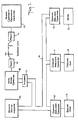
- the cooking appliance computers 10, 11 and 12 are interconnected by a communication bus 16 to an interface 17.
- the interface 17 couples the bus 16 to a local (e.g., store) computer 18 which, in turn, is coupled to a suitable modem 19 comprising a telephone.
- the telephone of the modem 19 is connected by telephone lines 20 to a remote modem 21 including a telephone and similar to the modem 19.
- the cooking appliance computers 10, 11 and 12 may also be connected by the communication bus 16 to one or more remote status indicators 25 which preferably are of a type described and claimed in copending application Serial No. 911,480, filed September 25, 1986.
- the local computer may be a personal computer of any well-known type and may serve as a control computer coupled to the cooking appliance computer for controlling the cooking appliance computer in setting the desired value of at least one parameter of the cooking computer.
- the remote modem 21 is coupled to a remote computer, which may, for example, be a remote mainframe computer 22.
- the remote mainframe computer, the local computer, the interface, or any of the cooking appliance computers can serve as the control computer.
- the control computer may be the local cooking computer 18 and the remote control computer may also be coupled to the local control cooking computer 18 for controlling the local control cooking computer 18 for controlling the cooking appliance computer 10, 11 or 12 and for setting the desired value of at least one parameter thereof.
- the control computer can send messages and receive messages from the cooking appliance computers.
- the cooking computer communication system comprises a cooking appliance computer for setting a desired value of at least one parameter, for example, temperature, of a cooking computer 10, 11 or 12.
- the cooking computer communication system also comprises a monitor computer coupled to the cooking appliance computer for monitoring the cooking appliance computer in setting the desired value.
- the monitor computer may be, for example, the local computer 18 or the remote mainframe computer 22.
- the monitor computer may be, for example, the local cooking computer 18 and the communication system may include a remote monitor cooking computer 22 coupled to the local monitor cooking computer for monitoring the local monitor cooking computer for monitoring the cooking appliance computer in setting the desired value.
- the remote control cooking computer may also be coupled to the local control cooking computer for controlling the local control cooking computer for controlling the cooking appliance computer in setting the desired value.
- the cooking computer communication system comprises a first cooking appliance computer 10 for setting a desired value of at least one parameter, for example, temperature, of a cooking unit.
- the system also includes a second cooking appliance computer 11 for setting a desired value of at least one parameter, for example, temperature, of a second cooking unit.
- the system also includes means for sensing the actual value of the parameter of the second cooking unit.
- the system also includes a control computer 18 coupled to the first and second cooking appliance computers and responsive to a first inquiry from the first cooking appliance computer as to whether the control computer 18 has a message to transmit to the second cooking appliance computer 11 for transmitting a message to the second cooking appliance computer 11.
- the second cooking appliance computer 11 is coupled to the first cooking appliance computer 10 and is responsive to an inquiry therefrom as to whether the second cooking appliance computer has a message to transmit to the control computer for transmitting to the control computer 22 a message representing the actual value of the parameter of the second cooking unit.
- the control computer 22 is responsive to a second inquiry from the first cooking appliance computer for transmitting to the second cooking appliance computer 11 a second message relating to setting a desired value of the parameter of the second unit.
- a microcomputer 23 includes a central processing unit which receives an input from the keyboard 24 which may, for example, comprise a capacitive keyboard.
- the apparatus includes a conventional power supply 25, a reset circuit 26 for resetting the microcomputer when renewing power in the power supply, a clock oscillator 27 for providing clock pulses to the microcomputer 23, a temperature sensor circuit 28 for sensing the temperature within the cooking apparatus, an audible alarm 29, an alpha-numeric display 30 and indicator lights 31.
- the apparatus also includes an input status circuit 32 which may, for example, be responsive to a door switch (not shown) and to the open/close position of the drain valve (not shown).
- the microcomputer controls an output relay circuit 33 which may, for example, control the gas valves of a burner or a heating element or microwave or other heating means or cooling means.
- the apparatus also includes a communication port 35 for transmitting signals to and from other apparatus.
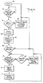
- Fig. 3 a flow chart for the remote computer 22.
- the remote computer 22 is programmed in accordance with the Fig. 3 flow chart.
- the programmed remote computer has a "query for selection" microprocessor portion 50 which may, for example, wait for a query selection by an operator at the remote computer.
- One of the selection possibilities is to query a cooking appliance computer's set temperature.
- the "query for selection” microprocessor portion 50 applies the query selection to a "valid selection?" microprocessor portion 51. If the selection is an invalid selection, the "no" output of the microprocessor portion 51 applies a signal to the microprocessor portion 50.
- Valid selections may be, for example, "query set temperature", “query cook time", “query inventory”, or “perform maintenance and operational tests” or "program a new cook time” or "program a new set temperature”.
- the "yes" output of the microprocessor portion 51 applies a signal to the "format message” microprocessor portion 52.
- the microprocessor portion 52 then formats a message which may be a function code which is a unique number meaning, for example, "read cook temperature”.
- the microprocessor portion 52 applies the formatted message to a "transmit message” microprocessor portion 53 which is coupled through the modem 21 of Fig. 1 to the telephone lines 20.
- the microprocessor portion 53 also applies a signal to a "return message expected?” microprocessor portion 54.
- the "no" output of the microprocessor portion 54 applies a signal to the "query for selection" microprocessor portion 50 which then is in control.
- the "yes" output of the microprocessor portion 54 applies a signal to a "return message received” microprocessor portion 55.
- the "return message received” microprocessor portion 55 waits for the return message while the "no" output of the microprocessor portion 55 is coupled to a "response time out?" microprocessor portion 56 which performs a time out sequence.
- the "no” output of the microprocessor portion 56 is coupled to the input of the microprocessor portion 55.
- the "yes” output of the microprocessor portion 56 is coupled to a "report error condition” microprocessor portion 57.
- the microprocessor portion 57 is coupled to the "query for selection" microprocessor portion 50 which again becomes in control.
- the "yes" output of the microprocessor portion 55 is coupled to a "report messages reply" microprocessor portion 58 which relays the reply to the remote computer console or display (not shown).
- the control returns to the microprocessor portion 50 which waits for a new selection.
- the local computer 18 which may be under the control of a store manager is programmed in accordance with the flow chart represented in Fig. 4. Power may be applied to the local computer by depressing a suitable key of a "start" microprocessor portion 60. The local computer then automatically enters an idle loop utilizing an "any query from remote computer?" microprocessor portion 61 having a "no" output coupled to the input of the microprocessor portion 61. The microprocessor portion 61 awaits a telephone call from the remote mainframe computer.
- the "yes" output of the microprocessor portion 61 is coupled to a "valid request?" microprocessor portion 62 for testing the validity of any message received.
- the "no" output of the microprocessor portion 62 is coupled to a "respond to remote computer with error message” microprocessor portion 63.
- the microprocessor portion 63 is coupled to the "start” portion 60 to return control to the "start” portion.
- the "yes" output of the microprocessor portion 62 is coupled to a "format command" microprocessor portion 64 which is, for example, for formatting a command for the bus 16.
- the valid message command is transmitted by the microprocessor portion 64 to a "transmit command to interface card" microprocessor portion 65.
- the interface card includes an interface microprocessor between the local computer and the bus 16 as represented by interface 17 of Fig. 1.
- the local computer Based upon the content of the message, the local computer either waits for another query from the remote computer 22 or enters a timed wait loop utilizing a "message received from interface card” microprocessor portion 67 having a “no” output coupled to a "response time out?” microprocessor portion 68 having its "no" output coupled to the input of microprocessor portion 67.
- the output of the microprocessor portion 65 is coupled to a "response required" microprocessor portion 66 having a “no" output coupled to the start portion 60 to return control thereto which awaits another query from the remote computer.
- the "yes" output of the microprocessor portion 66 is coupled to the microprocessor portion 67 described above.
- the "yes" output of the microprocessor portion 68 is coupled to a "report error condition to remote computer" microprocessor portion 69 which is, in turn, coupled to the portion 60 to await another query from the remote computer and control returns to the "start" portion 60 of the main control loop.
- the "yes" output of the microprocessor portion 67 is coupled to a "format reply message” microprocessor portion 70 which formats a reply message for the remote computer.
- the microprocessor portion 70 is coupled to a "send reply to remote computer” microprocessor portion 71 which is also coupled to the "start" portion 60 of the local computer. After transmitting the reply message, the local computer then returns to its idle loop 60, 61.
- a "start” microprocessor portion 72 is actuated upon reset of the interface 17.
- the "start” microprocessor portion 72 is coupled to a "any message from SCK interface bus?” microprocessor portion 73.
- the “no" output of the microprocessor portion 73 is coupled to an "any command from local computer?” microprocessor portion 74.
- the “no" output of the microprocessor portion 74 is coupled to the "start” microprocessor portion 72, causing the microprocessor to remain in its idle loop 72, 73, 74, waiting for one of two events to occur.
- One event is a message from the interface bus 16 and the other event is a command from the local computer 18. The occurrence of each event will be described separately hereinafter.
- a message from the SCK interface bus 16 may be identified by an interrupt signal.
- the "yes" output of the microprocessor portion 73 causes the “capture message into input message buffer” microprocessor portion 75 and then it is analyzed.
- the microprocessor portion 75 is coupled to a “is message for interface?" microprocessor portion 76.
- the “no" output of the microprocessor portion 76 is coupled to a "is message for local computer?” microprocessor portion 77.
- the “no” output of the microprocessor portion 77 is coupled to a "clear message from input buffer” microprocessor portion 78 which is coupled to the idle loop 72, 73, 74.
- a message for the interface 17 is typically a request for a message, although it may be other messages sent on a global basis.
- the interface microprocessor portion 76 has its "yes" output coupled to a "does interface have a response to the message?" microprocessor portion 79.
- the master polls the interface 17 and the cooking appliance computers to put an output message onto the bus 16.
- the interface microprocessor 17 determines whether a response to the bus query is available. If no output message to the bus is waiting, then the microprocessor portion 79 has its "no" output coupled to the microprocessor portion 78 and the idle loop continues.
- the "yes" output of the microprocessor portion 79 is coupled to a "time to send response?" microprocessor portion 80.
- the "no" output of the microprocessor portion 80 is applied to the input of the microprocessor portion 80.
- the “yes” output of the microprocessor portion 80 is coupled to a “send response to the message on the bus” microprocessor portion 81. After the response has been sent the microprocessor portion 81 actuates the "clear message from input buffer” microprocessor portion 78. The idle loop 72, 73, 74 then continues.
- the microprocessor portions 76 and 77 analyze the message and the "yes" output of the microprocessor portion 77 is coupled to a "send message to local computer" microprocessor portion 82.
- the local computer can issue a "pass function code” to the microprocessor portion 82, causing the microprocessor portion 82 to pass messages to the local computer 18 from the bus 16 that have the particular "pass function code".
- the microprocessor portion 82 sends the message to the local computer 18 via appropriate handshaking procedures.
- handshaking procedures is meant bi-directional communication to establish to each processor the presence of the other processor and that it is in a ready state. Each processor responds to the other processor's signal with its own signal for which the first processor is waiting.
- the input message is then cleared by the microprocessor portion 78 from the input buffer and the idle loop 72, 73, 74 continues.
- the interface microprocessor may also be interrupted by the local computer 18. Commands from the local computer 18 are recognized by microprocessor portion 74 and the "yes" output of the microprocessor portion 74 is coupled to a "process local computer command” microprocessor portion 83 which is coupled to the start portion 72 as part of the main idle loop. Commands from the local computer 18 to the microprocessor of the interface 17 may, for example, be: "reset buffers", "next data word is device code", "buffer data from local computer to bus output buffer”. Diagnostic may also be initiated by local computer commands. Upon completion of processing the local computer command, the interface microprocessor returns to its main idle loop.
- the local computer can change the type of message the interface 17 is seeking.
- the local computer is reprogrammable at its location and can change the characteristics of the "process local computer command" microprocessor portion 83.
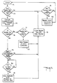
- FIG. 6 of the drawings there is represented a flow chart for a cooking appliance computer master unit programmed in accordance with the flow chart.
- the cooking appliance computer slave units may be programmed in accordance with the same flow chart with the omission of the "time to poll next unit?" microprocessor portion and the "poll next sequential unit” microprocessor portion to be described subsequently.
- the flow chart represents a polling system of implementation although token ring or other communication bus architectures would equally suffice.
- a "start” microprocessor portion 84 is coupled to an "any input messages?" microprocessor portion 85.
- the "no" output of the microprocessor portion 85 is coupled to a "any message to output?” microprocessor portion 86.
- the "no" output of the microprocessor portion 86 is coupled to a "time to poll next unit?" microprocessor portion 87.
- the "no" output of the microprocessor portion 87 is coupled to a "perform cooking appliance process control function" microprocessor portion 88.
- the cooking appliance process control function performed may, for example, be to reset the set temperature as described, for example, in Serial No. 840,362, filed March 17, 1986.
- the microprocessor portion 88 is then coupled to the "start” microprocessor portion 84 to form the main idle loop.
- the "yes" output of the microprocessor portion 85 is coupled to an "is input message valid?" microprocessor portion 89.
- the validity of the message may be determined in any suitable manner, for example, by a check sum, unit number, or function code.
- a valid message would, for example, be a query for the current cooking appliance temperature. If the message is invalid, the "no" output of the microprocessor portion 89 is coupled to a "discard input message" microprocessor portion 91 which discards the input message and is coupled to the microprocessor portion 86.
- a message may be considered invalid if it has, for example, an incorrect check sum or if the destination unit number in the message does not match the unit that has received the message.
- the "yes" output of the microprocessor portion 89 is coupled to a "process input message” microprocessor portion 90 which may then have an output message and is coupled to the microprocessor portion 86.
- the output message may, for example, be the cooking appliance temperature.
- the microprocessor portion 86 When no input messages are present on the communication bus 16, the microprocessor portion 86 then checks to determine whether there is any message to output onto the communication bus 16. When there is a message waiting for outputting, the cooking appliance computer master must wait for the appropriate time before the output message is sent. Cooking appliance computers other than the master only assert their messages when they are polled. The master asserts its message at timed intervals.
- the "yes" output of the microprocessor portion 86 is coupled to a "correct time to output message?" microprocessor portion 92.
- the "yes” output of the microprocessor portion 92 is coupled to an "output message onto SCK bus” microprocessor portion 93.
- the microprocessor portion 93 and the "no" output of the microprocessor portion 92 are coupled to the microprocessor portion 88.
- control is passed to the microprocessor portion 88 which performs the cooking appliance process control function.
- the master omits sending the polling message to the slaves when it transmits any information over the bus 16.
- the master cooking appliance computer checks to determine whether it is time to poll the next unit by means of the master microprocessor portion 87 having its "yes" output connected to a "poll next sequential unit” microprocessor portion 94.
- the master unit When it is the correct time to poll the other units, the master unit issues a polling message onto the communication bus 16 by means of microprocessor portion 94. All units on the bus 16 are ready to accept the transmission. Units other than the master will not perform the polling function as described in connection with microprocessor portions 87 and 94.
- the microprocessor portion 94 is coupled to the microprocessor portion 88 so that upon completing the polling function, the master cooking appliance computer unit will proceed to perform the cooking appliance process control function.
- the cooking appliance process control function is performed by all cooking appliance computers coupled to the bus 16 continuously, in addition to the communication functions described herein with respect to the master.
- the communication system is capable of controlling cooking appliance computers, for example, from a local computer or from a remote mainframe computer.
- the cooking appliance computers can be controlled to receive messages from the local computer or the remote computer or from one another and to transmit messages to the local computer and to the remote computer and to one another.
- the cooking appliance computers can also transmit messages to the remote status indicator 25 in the manner described in copending US Patent Application Serial No. 911,480, filed September 25, 1986.
- the communication system may handle a variety of messages including messages relating to inventory control and load level for the individual cooking appliance computers. Additional messages such as commands to start and terminate the cooking appliance computers and the local computer and to turn off any or all power supplies in the store can be issued from the remote computer.
- the apparatus may include a bar coding system in which the bar code is read by a conventional reader and represents a product identification.
- the product identification may be utilized by the control computer to set the desired value of at least one parameter of the cocking appliance computer.
- the bar code may also be utilized by the control computer for inventory control.
Landscapes
- Engineering & Computer Science (AREA)
- Automation & Control Theory (AREA)
- Chemical & Material Sciences (AREA)
- Mechanical Engineering (AREA)
- General Engineering & Computer Science (AREA)
- Food Science & Technology (AREA)
- Physics & Mathematics (AREA)
- Combustion & Propulsion (AREA)
- General Physics & Mathematics (AREA)
- Selective Calling Equipment (AREA)
- Electric Ovens (AREA)
- Cookers (AREA)
- Frying-Pans Or Fryers (AREA)
- Thermally Insulated Containers For Foods (AREA)
- Communication Control (AREA)
- Electric Stoves And Ranges (AREA)
Abstract
Description
- This invention relates to a cooking computer communication system according to the preceding part of claim 1.
- Heretofore, cooking appliance computers have been utilized individually with cooking appliances with each cooking appliance computer controlling its associated cooking appliance (see US-A 43 80 698 and US-A 46 26 662). The prior art system, disclosed in the first mentioned document, requires two independent bus systems to operate. The two bus systems are "send" and "receive" bus systems for a master unit. This system also requires a master dedicated unit and slave units. The second mentioned document relates to a multifunktion feedback cooking apparatus, a part of it being a temperature transducer, applying feedback information to an analog-to-digital converter and then to a central processing unit.
- It is an object of the present invention, therefore, to provide a new and improved cooking computer communication system which avoids one or more of the disadvantages of prior cooking computer systems.
- It is another object of the invention to provide a new and improved cooking computer communication system which controls one or more parameters of one or more cooking appliance computers remotely or locally or both.
- It is another object of the invention to provide a new and improved cooking computer communication system which monitors one or more cooking appliance computers in setting a desired value of one or more parameters thereof.
- It is another object of the invention to provide a new and improved cooking computer communication system by which the manager of a store having several cooking appliance computers therein can locally control one or more cooking appliance computers by setting a desired value of at least one parameter thereof or can monitor the operation of the cooking appliance computers or both.
- It is another object of the invention to provide a new and improved cooking computer communication system by which a corporate manager remote from the location of cooking appliance computers can control or monitor the operation of one or more cooking appliance computers or both.
- It is another object of the invention to provide a new and improved cooking computer communication system in which the cooking computers can communicate with each other.
- These objects are achieved by the characterizing features of the claims.
- In accordance with the invention, the control computer can control individually, for example, the temperatures of individual cooking appliance computers, record the inventories for the individual cooking appliances, monitor the operations of the individual cooking appliances, give and receive messages to and from the individual cooking appliance computers, and the individual cooking appliance computers can communicate with each other.
- In a kitchen which has a plurality of cooking appliance computers a control computer can control locally or remotely the individual cooking appliance computers in accordance with the invention.
- Also in accordance with the invention, a cooking computer communication system comprises a first cooking appliance computer for setting a desired value of at least one parameter of a cooking unit and a second cooking appliance computer for setting a desired value of at least one parameter of a second cooking unit. The system also includes means for sensing the actual value of the parameter of the second cooking unit. The system also includes a control computer coupled to the first and second cooking appliance units and responsive to a first inquiry from the first cooking appliance computer as to whether the control computer has a message to transmit to the second cooking appliance computer for transmitting a message to the second cooking appliance computer. The second cooking appliance computer is coupled to the first cooking appliance computer and is responsive to an inquiry therefrom as to whether the second cooking appliance computer has a message to transmit to the control computer for transmitting to the control computer a message representing the actual value of the parameter of a second cooking unit. The control computer is responsive to a second inquiry from the first cooking appliance computer for transmitting to the second cooking appliance computer a second message relating to setting a desired value of the aforesaid parameter of the second cooking unit.
- For a better understanding of the present invention, together with other and further objects thereof, reference is made to the following description, taken in connection with the accompanying drawings, and its scope will be pointed out in the appended claims.
- Referring now to the drawings:
- Fig. 1 is a schematic diagram of a cooking computer communication system constructed in accordance with the invention and the cooking appliances controlled thereby;
- Fig. 2 is a schematic diagram representing apparatus including a microcomputer and usable in the Fig. 1 cooking computer communication system;
- Fig. 3 is a flow-chart comprising a schematic representation of a portion of a remote microcomputer which operates according to a computer program produced according to the flow-chart;
- Fig. 4 is a flow-chart comprising a schematic representation of a portion of a local microcomputer which operates according to a computer program produced according to the flow-chart;
- Fig. 5 is a flow-chart comprising a schematic representation of a portion of an interface microprocessor which operates according to a computer program produced according to the flow-chart; and
- Fig. 6 is a flow-chart comprising a schematic representation of a portion of a cooking appliance computer which serves as a master unit which operates according to a computer program produced according to the flow-chart.
- Before referring to the drawings in detail, it will be understood that for purposes of clarity, the apparatus represented in the block diagrams of Figs. 2 to 6, inclusive, utilize, for example, individually an analog to digital converter and a microprocessor which includes such hardware as a central processing unit, program and random access memories, timing and control circuitry, input-output interface devices and other digital subsystems necessary to the operation of each central processing unit as is well understood by those skilled in the art. Each microprocessor operates according to the corresponding computer program produced according to the corresponding flow-chart represented in the drawings.
- Referring now more particularly to Fig. 1 of the drawings, a food store may include, for example,
cooking appliance computers 10, 11, and 12, for controlling one or more parameters, for example, the temperature, of the cooking appliances associated therewith. For the purposes of this specification and claims, the term "cooking unit" or "cooking appliance" shall be understood to include a temperature-control unit which may, for example, be a cooling unit. - The
cooking appliance computers 10, 11, 12 may, for example, be of a type used in apparatus described and claimed in US applications Serial No. 840,362, filed March 17, 1986, and in Serial No. 943,949, filed December 18, 1986, and in Serial No. 937,988, filed December 4, 1986, and in Serial No. 934,700, filed November 25, 1986, and in Serial No. 911,480, filed September 25, 1986. - A cooking computer communication system in accordance with the invention comprises a cooking appliance computer for setting a desired value of at least one parameter of a cooking computer. This cooking appliance computer may, for example, be any of the
computers 10, 11 and 12 coupled to abaking oven 13, acooling unit 14 and afryer 15, respectively, for setting a desired value of at least one parameter of a cooking computer. In this connection, the computer 11 shall be understood to be a cooking appliance computer, for example, a temperature-control computer for setting the temperature of thecooling unit 14 utilized in the cooking system. - The
cooking appliance computers 10, 11 and 12 are interconnected by acommunication bus 16 to aninterface 17. Theinterface 17 couples thebus 16 to a local (e.g., store)computer 18 which, in turn, is coupled to asuitable modem 19 comprising a telephone. The telephone of themodem 19 is connected bytelephone lines 20 to aremote modem 21 including a telephone and similar to themodem 19. Thecooking appliance computers 10, 11 and 12 may also be connected by thecommunication bus 16 to one or moreremote status indicators 25 which preferably are of a type described and claimed in copending application Serial No. 911,480, filed September 25, 1986. The local computer may be a personal computer of any well-known type and may serve as a control computer coupled to the cooking appliance computer for controlling the cooking appliance computer in setting the desired value of at least one parameter of the cooking computer. Theremote modem 21 is coupled to a remote computer, which may, for example, be aremote mainframe computer 22. - As will be apparent hereinafter, the remote mainframe computer, the local computer, the interface, or any of the cooking appliance computers can serve as the control computer. The control computer may be the
local cooking computer 18 and the remote control computer may also be coupled to the localcontrol cooking computer 18 for controlling the localcontrol cooking computer 18 for controlling thecooking appliance computer 10, 11 or 12 and for setting the desired value of at least one parameter thereof. The control computer can send messages and receive messages from the cooking appliance computers. The cooking computer communication system comprises a cooking appliance computer for setting a desired value of at least one parameter, for example, temperature, of acooking computer 10, 11 or 12. The cooking computer communication system also comprises a monitor computer coupled to the cooking appliance computer for monitoring the cooking appliance computer in setting the desired value. The monitor computer may be, for example, thelocal computer 18 or theremote mainframe computer 22. The monitor computer may be, for example, thelocal cooking computer 18 and the communication system may include a remotemonitor cooking computer 22 coupled to the local monitor cooking computer for monitoring the local monitor cooking computer for monitoring the cooking appliance computer in setting the desired value. The remote control cooking computer may also be coupled to the local control cooking computer for controlling the local control cooking computer for controlling the cooking appliance computer in setting the desired value. - The cooking computer communication system comprises a first cooking appliance computer 10 for setting a desired value of at least one parameter, for example, temperature, of a cooking unit. The system also includes a second cooking appliance computer 11 for setting a desired value of at least one parameter, for example, temperature, of a second cooking unit. The system also includes means for sensing the actual value of the parameter of the second cooking unit.
- The system also includes a
control computer 18 coupled to the first and second cooking appliance computers and responsive to a first inquiry from the first cooking appliance computer as to whether thecontrol computer 18 has a message to transmit to the second cooking appliance computer 11 for transmitting a message to the second cooking appliance computer 11. - The second cooking appliance computer 11 is coupled to the first cooking appliance computer 10 and is responsive to an inquiry therefrom as to whether the second cooking appliance computer has a message to transmit to the control computer for transmitting to the control computer 22 a message representing the actual value of the parameter of the second cooking unit. The
control computer 22 is responsive to a second inquiry from the first cooking appliance computer for transmitting to the second cooking appliance computer 11 a second message relating to setting a desired value of the parameter of the second unit. - Referring now more particularly to Fig. 2 of the drawings, a microcomputer 23 includes a central processing unit which receives an input from the
keyboard 24 which may, for example, comprise a capacitive keyboard. - The apparatus includes a
conventional power supply 25, areset circuit 26 for resetting the microcomputer when renewing power in the power supply, aclock oscillator 27 for providing clock pulses to the microcomputer 23, atemperature sensor circuit 28 for sensing the temperature within the cooking apparatus, anaudible alarm 29, an alpha-numeric display 30 andindicator lights 31. The apparatus also includes aninput status circuit 32 which may, for example, be responsive to a door switch (not shown) and to the open/close position of the drain valve (not shown). The microcomputer controls anoutput relay circuit 33 which may, for example, control the gas valves of a burner or a heating element or microwave or other heating means or cooling means. The apparatus also includes acommunication port 35 for transmitting signals to and from other apparatus. - Referring now to Figs. 1 and 3, there is represented in Fig. 3 a flow chart for the
remote computer 22. Theremote computer 22 is programmed in accordance with the Fig. 3 flow chart. The programmed remote computer has a "query for selection" microprocessor portion 50 which may, for example, wait for a query selection by an operator at the remote computer. One of the selection possibilities is to query a cooking appliance computer's set temperature. The "query for selection" microprocessor portion 50 applies the query selection to a "valid selection?"microprocessor portion 51. If the selection is an invalid selection, the "no" output of themicroprocessor portion 51 applies a signal to the microprocessor portion 50. Valid selections may be, for example, "query set temperature", "query cook time", "query inventory", or "perform maintenance and operational tests" or "program a new cook time" or "program a new set temperature". - If the
microprocessor portion 51 determines that the query selection is a valid selection, the "yes" output of themicroprocessor portion 51 applies a signal to the "format message"microprocessor portion 52. Themicroprocessor portion 52 then formats a message which may be a function code which is a unique number meaning, for example, "read cook temperature". Themicroprocessor portion 52 applies the formatted message to a "transmit message"microprocessor portion 53 which is coupled through themodem 21 of Fig. 1 to the telephone lines 20. Themicroprocessor portion 53 also applies a signal to a "return message expected?"microprocessor portion 54. - If no return message is expected, the "no" output of the
microprocessor portion 54 applies a signal to the "query for selection" microprocessor portion 50 which then is in control. - If a return message is expected, the "yes" output of the
microprocessor portion 54 applies a signal to a "return message received"microprocessor portion 55. The "return message received"microprocessor portion 55 waits for the return message while the "no" output of themicroprocessor portion 55 is coupled to a "response time out?"microprocessor portion 56 which performs a time out sequence. The "no" output of themicroprocessor portion 56 is coupled to the input of themicroprocessor portion 55. The "yes" output of themicroprocessor portion 56 is coupled to a "report error condition"microprocessor portion 57. Themicroprocessor portion 57 is coupled to the "query for selection" microprocessor portion 50 which again becomes in control. - If a response is received before the
microprocessor portion 56 times out, the "yes" output of themicroprocessor portion 55 is coupled to a "report messages reply"microprocessor portion 58 which relays the reply to the remote computer console or display (not shown). Thus, if a response does not arrive within a reasonable time an error condition is reported to the microprocessor portion 50 or if a response is received in the predetermined reasonable time, the control returns to the microprocessor portion 50 which waits for a new selection. - Referring now more particularly to Figs. 1 and 4, the
local computer 18 which may be under the control of a store manager is programmed in accordance with the flow chart represented in Fig. 4. Power may be applied to the local computer by depressing a suitable key of a "start"microprocessor portion 60. The local computer then automatically enters an idle loop utilizing an "any query from remote computer?"microprocessor portion 61 having a "no" output coupled to the input of themicroprocessor portion 61. Themicroprocessor portion 61 awaits a telephone call from the remote mainframe computer. - The "yes" output of the
microprocessor portion 61 is coupled to a "valid request?"microprocessor portion 62 for testing the validity of any message received. The "no" output of themicroprocessor portion 62 is coupled to a "respond to remote computer with error message"microprocessor portion 63. Themicroprocessor portion 63 is coupled to the "start"portion 60 to return control to the "start" portion. - The "yes" output of the
microprocessor portion 62 is coupled to a "format command"microprocessor portion 64 which is, for example, for formatting a command for thebus 16. The valid message command is transmitted by themicroprocessor portion 64 to a "transmit command to interface card"microprocessor portion 65. As will be more fully described subsequently, the interface card includes an interface microprocessor between the local computer and thebus 16 as represented byinterface 17 of Fig. 1. Based upon the content of the message, the local computer either waits for another query from theremote computer 22 or enters a timed wait loop utilizing a "message received from interface card"microprocessor portion 67 having a "no" output coupled to a "response time out?"microprocessor portion 68 having its "no" output coupled to the input ofmicroprocessor portion 67. - The output of the
microprocessor portion 65 is coupled to a "response required"microprocessor portion 66 having a "no" output coupled to thestart portion 60 to return control thereto which awaits another query from the remote computer. The "yes" output of themicroprocessor portion 66 is coupled to themicroprocessor portion 67 described above. - If the
microprocessor portion 68 times out before a response is received from theinterface card 17, the "yes" output of themicroprocessor portion 68 is coupled to a "report error condition to remote computer" microprocessor portion 69 which is, in turn, coupled to theportion 60 to await another query from the remote computer and control returns to the "start"portion 60 of the main control loop. - If a message is received by the
microprocessor portion 67 within the predetermined time period, the "yes" output of themicroprocessor portion 67 is coupled to a "format reply message" microprocessor portion 70 which formats a reply message for the remote computer. The microprocessor portion 70 is coupled to a "send reply to remote computer"microprocessor portion 71 which is also coupled to the "start"portion 60 of the local computer. After transmitting the reply message, the local computer then returns to itsidle loop - Referring now more particularly to Fig. 5 of the drawings, the flow chart of the programmed
interface 17 is there represented. A "start" microprocessor portion 72 is actuated upon reset of theinterface 17. The "start" microprocessor portion 72 is coupled to a "any message from SCK interface bus?" microprocessor portion 73. The "no" output of the microprocessor portion 73 is coupled to an "any command from local computer?"microprocessor portion 74. The "no" output of themicroprocessor portion 74 is coupled to the "start" microprocessor portion 72, causing the microprocessor to remain in itsidle loop 72, 73, 74, waiting for one of two events to occur. One event is a message from theinterface bus 16 and the other event is a command from thelocal computer 18. The occurrence of each event will be described separately hereinafter. - A message from the
SCK interface bus 16 may be identified by an interrupt signal. When a message is received from theinterface bus 16, the "yes" output of the microprocessor portion 73 causes the "capture message into input message buffer"microprocessor portion 75 and then it is analyzed. Themicroprocessor portion 75 is coupled to a "is message for interface?"microprocessor portion 76. The "no" output of themicroprocessor portion 76 is coupled to a "is message for local computer?"microprocessor portion 77. The "no" output of themicroprocessor portion 77 is coupled to a "clear message from input buffer" microprocessor portion 78 which is coupled to theidle loop 72, 73, 74. - A message for the
interface 17 is typically a request for a message, although it may be other messages sent on a global basis. Theinterface microprocessor portion 76 has its "yes" output coupled to a "does interface have a response to the message?"microprocessor portion 79. - As will be described subsequently, the master polls the
interface 17 and the cooking appliance computers to put an output message onto thebus 16. Theinterface microprocessor 17 determines whether a response to the bus query is available. If no output message to the bus is waiting, then themicroprocessor portion 79 has its "no" output coupled to the microprocessor portion 78 and the idle loop continues. - When a response is waiting to be applied as a bus message, the "yes" output of the
microprocessor portion 79 is coupled to a "time to send response?"microprocessor portion 80. - The "no" output of the
microprocessor portion 80 is applied to the input of themicroprocessor portion 80. The "yes" output of themicroprocessor portion 80 is coupled to a "send response to the message on the bus"microprocessor portion 81. After the response has been sent themicroprocessor portion 81 actuates the "clear message from input buffer" microprocessor portion 78. Theidle loop 72, 73, 74 then continues. - When the message on the
bus 16 is not for theinterface 17 directly, themicroprocessor portions microprocessor portion 77 is coupled to a "send message to local computer"microprocessor portion 82. The local computer can issue a "pass function code" to themicroprocessor portion 82, causing themicroprocessor portion 82 to pass messages to thelocal computer 18 from thebus 16 that have the particular "pass function code". If it is determined that the message is for thelocal computer 18, themicroprocessor portion 82 sends the message to thelocal computer 18 via appropriate handshaking procedures. By handshaking procedures is meant bi-directional communication to establish to each processor the presence of the other processor and that it is in a ready state. Each processor responds to the other processor's signal with its own signal for which the first processor is waiting. The input message is then cleared by the microprocessor portion 78 from the input buffer and theidle loop 72, 73, 74 continues. - The interface microprocessor may also be interrupted by the
local computer 18. Commands from thelocal computer 18 are recognized bymicroprocessor portion 74 and the "yes" output of themicroprocessor portion 74 is coupled to a "process local computer command"microprocessor portion 83 which is coupled to the start portion 72 as part of the main idle loop. Commands from thelocal computer 18 to the microprocessor of theinterface 17 may, for example, be: "reset buffers", "next data word is device code", "buffer data from local computer to bus output buffer". Diagnostic may also be initiated by local computer commands. Upon completion of processing the local computer command, the interface microprocessor returns to its main idle loop. - The local computer can change the type of message the
interface 17 is seeking. The local computer is reprogrammable at its location and can change the characteristics of the "process local computer command"microprocessor portion 83. - Referring now to Fig. 6 of the drawings, there is represented a flow chart for a cooking appliance computer master unit programmed in accordance with the flow chart. The cooking appliance computer slave units may be programmed in accordance with the same flow chart with the omission of the "time to poll next unit?" microprocessor portion and the "poll next sequential unit" microprocessor portion to be described subsequently. The flow chart represents a polling system of implementation although token ring or other communication bus architectures would equally suffice. A "start"
microprocessor portion 84 is coupled to an "any input messages?"microprocessor portion 85. The "no" output of themicroprocessor portion 85 is coupled to a "any message to output?"microprocessor portion 86. The "no" output of themicroprocessor portion 86 is coupled to a "time to poll next unit?"microprocessor portion 87. The "no" output of themicroprocessor portion 87 is coupled to a "perform cooking appliance process control function"microprocessor portion 88. The cooking appliance process control function performed may, for example, be to reset the set temperature as described, for example, in Serial No. 840,362, filed March 17, 1986. Themicroprocessor portion 88 is then coupled to the "start"microprocessor portion 84 to form the main idle loop. In checking for input messages from thecommunication bus 16, the "yes" output of themicroprocessor portion 85 is coupled to an "is input message valid?" microprocessor portion 89. The validity of the message may be determined in any suitable manner, for example, by a check sum, unit number, or function code. A valid message would, for example, be a query for the current cooking appliance temperature. If the message is invalid, the "no" output of the microprocessor portion 89 is coupled to a "discard input message"microprocessor portion 91 which discards the input message and is coupled to themicroprocessor portion 86. A message may be considered invalid if it has, for example, an incorrect check sum or if the destination unit number in the message does not match the unit that has received the message. The "yes" output of the microprocessor portion 89 is coupled to a "process input message"microprocessor portion 90 which may then have an output message and is coupled to themicroprocessor portion 86. The output message may, for example, be the cooking appliance temperature. - When no input messages are present on the
communication bus 16, themicroprocessor portion 86 then checks to determine whether there is any message to output onto thecommunication bus 16. When there is a message waiting for outputting, the cooking appliance computer master must wait for the appropriate time before the output message is sent. Cooking appliance computers other than the master only assert their messages when they are polled. The master asserts its message at timed intervals. The "yes" output of themicroprocessor portion 86 is coupled to a "correct time to output message?"microprocessor portion 92. The "yes" output of themicroprocessor portion 92 is coupled to an "output message onto SCK bus"microprocessor portion 93. Themicroprocessor portion 93 and the "no" output of themicroprocessor portion 92 are coupled to themicroprocessor portion 88. Thus, if it was not the correct time to transmit the message or if a message was transmitted, then control is passed to themicroprocessor portion 88 which performs the cooking appliance process control function. The master omits sending the polling message to the slaves when it transmits any information over thebus 16. - When there are no input messages and no waiting or pending output messages, the master cooking appliance computer checks to determine whether it is time to poll the next unit by means of the
master microprocessor portion 87 having its "yes" output connected to a "poll next sequential unit"microprocessor portion 94. - When it is the correct time to poll the other units, the master unit issues a polling message onto the
communication bus 16 by means ofmicroprocessor portion 94. All units on thebus 16 are ready to accept the transmission. Units other than the master will not perform the polling function as described in connection withmicroprocessor portions - The
microprocessor portion 94 is coupled to themicroprocessor portion 88 so that upon completing the polling function, the master cooking appliance computer unit will proceed to perform the cooking appliance process control function. - The cooking appliance process control function is performed by all cooking appliance computers coupled to the
bus 16 continuously, in addition to the communication functions described herein with respect to the master. - From the foregoing description it will be apparent that the communication system is capable of controlling cooking appliance computers, for example, from a local computer or from a remote mainframe computer. The cooking appliance computers can be controlled to receive messages from the local computer or the remote computer or from one another and to transmit messages to the local computer and to the remote computer and to one another. The cooking appliance computers can also transmit messages to the
remote status indicator 25 in the manner described in copending US Patent Application Serial No. 911,480, filed September 25, 1986. The communication system may handle a variety of messages including messages relating to inventory control and load level for the individual cooking appliance computers. Additional messages such as commands to start and terminate the cooking appliance computers and the local computer and to turn off any or all power supplies in the store can be issued from the remote computer. - The apparatus may include a bar coding system in which the bar code is read by a conventional reader and represents a product identification. The product identification may be utilized by the control computer to set the desired value of at least one parameter of the cocking appliance computer. The bar code may also be utilized by the control computer for inventory control.
Claims (11)
- A cooking appliance computer communication system comprising· at least two cooking appliance computer means (10, 11, 12) for setting a desired value of at least one parameter of at least two cooking appliances (13, 14, 15) and for sending messages,· a bus (16) and· control computer means (10, 11, 12, 17, 18, 22) coupled through said bus to said at least two cooking appliance computer means for receiving messages therefrom and for sending messages through said bus for controlling said cooking appliance computer means in setting said desired value,characterised in· that the bus (16) is a bi-directional bus, so that the at least two cooking appliance computer means (10, 11, 12) are able to bi-directionally communicate with said control computer means (10, 11, 12, 17, 18, 22), and with one another, for receiving messages and for sending messages.
- A cooking appliance computer communication system in accordance with claim 1, in which said control computer means is a local control computer means (18) and which system includes a remote control computer means (22) coupled to said local control computer means for controlling said local control computer means for controlling said cooking appliance computer means (10, 11, 12) in setting said desired value.
- A system in accordance with claim 1, in which said control computer means is a temperature control appliance computer (10, 11, 12).
- A system in accordance with claim 1, in which one of said cooking appliance computer means (10, 11, 12) serves as said control computer means.
- A system in accordance with claim 1, in which said control computer means is a local computer (18).
- A system in accordance with claim 1, in which said control computer means is a remote computer (22).
- A system in accordance with claim 1, which includes a local computer (18) and which also includes interface processor means (17) between said cooking appliance computer means (10, 11, 12) and said local computer and in which said control computer means comprises said interface processor means (17).
- A cooking computer communication system in accordance with claim 1, in which said control computer means is a monitor computer means (18, 22) coupled to said cooking appliance computer means (10, 11, 12) for monitoring said cooking appliance computer means in setting said desired value.
- A cooking computer communication system in accordance with claim 8, in which said monitor computer means is a local cooking computer means (18) and which system includes a remote computer means (22) coupled to said local monitor computer means for monitoring said cooking appliance computer means (10, 11, 12) in setting said desired value.
- A cooking computer communication system in accordance with claim 8, in which said control computer means is a local computer means (18) and which system includes a remote control computer means (22) coupled to said local control computer means for controlling said local control computer means for controlling said cooking appliance computer means (10, 11, 12) in setting said desired value.
- A cooking appliance computer communication system in accordance with claim 1,· in which one (10) of said at least two cooking appliance computer means (10, 11) is a first means and another (11) of said at least two cooking appliance computer means (10, 11) is a second means, and in which one (13) of said at least two appliances (13, 14) is a first appliance and another (14) is a second appliance, said system further comprising means for sensing the actual value of the parameter of said second cooking appliance (14),characterised in· that said control computer means (17, 18, 22) are responsive to a first inquiry, from said first cooking appliance computer means (10) as to whether said control computer means (17, 18, 22) has a message to transmit to said second cooking appliance computer means (11), for transmitting a message to said second cooking appliance computer means (11),· that said second cooking appliance computer means (11) are responsive to an inquiry, from said first cooking appliance computer means (10) as to whether the said second cooking appliance computer means (11) has a message to transmit to said control computer means (17, 18, 22), for transmitting to said control computer means (17, 18, 22) a message representing said actual value of said parameter of said cooking appliance (14), and· that said control computer means (17, 18, 22) are responsive to a second inquiry from said first cooking appliance computer means (10) for transmitting to said second cooking appliance computer means (11), a second message relating to setting a desired value of said parameter of said second cooking appliance (14).
Priority Applications (1)
| Application Number | Priority Date | Filing Date | Title |
|---|---|---|---|
| AT8888104960T ATE105090T1 (en) | 1987-03-31 | 1988-03-28 | TRANSMISSION SYSTEM FOR A COOKING COMPUTER. |
Applications Claiming Priority (2)
| Application Number | Priority Date | Filing Date | Title |
|---|---|---|---|
| US07/033,097 US4812963A (en) | 1987-03-31 | 1987-03-31 | Plural cooking computer communication system |
| US33097 | 1993-03-16 |
Publications (3)
| Publication Number | Publication Date |
|---|---|
| EP0285056A2 EP0285056A2 (en) | 1988-10-05 |
| EP0285056A3 EP0285056A3 (en) | 1989-03-01 |
| EP0285056B1 true EP0285056B1 (en) | 1994-04-27 |
Family
ID=21868541
Family Applications (1)
| Application Number | Title | Priority Date | Filing Date |
|---|---|---|---|
| EP88104960A Expired - Lifetime EP0285056B1 (en) | 1987-03-31 | 1988-03-28 | Cooking computer communication system |
Country Status (8)
| Country | Link |
|---|---|
| US (1) | US4812963A (en) |
| EP (1) | EP0285056B1 (en) |
| JP (1) | JPS63254322A (en) |
| AT (1) | ATE105090T1 (en) |
| AU (1) | AU613428B2 (en) |
| CA (1) | CA1286749C (en) |
| DE (2) | DE3889246D1 (en) |
| ES (1) | ES2051784T3 (en) |
Cited By (5)
| Publication number | Priority date | Publication date | Assignee | Title |
|---|---|---|---|---|
| EP2101229A1 (en) | 2008-03-13 | 2009-09-16 | Rational AG | Method for creating an intelligent human-machine interface for cooking devices |
| EP2101230A1 (en) | 2008-03-13 | 2009-09-16 | Rational AG | Method for creating an intelligent human-machine interface for cooking devices |
| DE102008014006A1 (en) | 2008-03-13 | 2009-09-17 | Rational Ag | Intelligent man-machine interface method for combi steam oven, involves inputting satisfaction indicated by user and/or monitoring person at time point selected by user and/or person via Intranet and/or Internet in wireless manner |
| DE102008013995A1 (en) | 2008-03-13 | 2009-09-24 | Rational Ag | Intelligent human-machine-interface providing method for e.g. tilting fry pan, in kitchen, involves sorting operating programs selected from cooking programs, cleaning programs, and/or diagnosing programs in preset operating program class |
| DE102008014007A1 (en) | 2008-03-13 | 2009-09-24 | Rational Ag | Intelligent man-machine interface providing method for use with combi-steamer in e.g. hotel, involves changing adjustment of cooking device, and outputting information about cooking device in dependence of user class classification |
Families Citing this family (73)
| Publication number | Priority date | Publication date | Assignee | Title |
|---|---|---|---|---|
| US5338157B1 (en) * | 1992-09-09 | 1999-11-02 | Sims Deltec Inc | Systems and methods for communicating with ambulat |
| US5043860A (en) * | 1989-05-12 | 1991-08-27 | Technology Licensing Corporation | Cooking appliance interface |
| US5241463A (en) * | 1989-06-05 | 1993-08-31 | White Consolidated Industries, Inc. | Control system for gas burners |
| US5126934A (en) * | 1989-06-09 | 1992-06-30 | Smart House, L.P. | Gas distribution system |
| US5051720A (en) * | 1989-11-13 | 1991-09-24 | Secure Telecom, Inc. | Remote control system using power line of remote site |
| EP0456872A1 (en) * | 1990-05-18 | 1991-11-21 | Food Automation-Service Techniques, Inc. | Food-processing apparatus |
| US5331575A (en) * | 1991-05-03 | 1994-07-19 | Technology Licensing Corporation | Shortening management system |
| US5818428A (en) * | 1993-01-21 | 1998-10-06 | Whirlpool Corporation | Appliance control system with configurable interface |
| US5321229A (en) * | 1993-04-05 | 1994-06-14 | Whirlpool Corporation | Remote control for a domestic appliance |
| ES2078144B1 (en) * | 1993-06-03 | 1998-01-16 | Fagor S Coop Ltda | CONTROL AND COMMUNICATION SYSTEM FOR DOMESTIC KITCHEN. |
| ES2078145B1 (en) * | 1993-06-03 | 1998-01-16 | Fagor S Coop Ltda | CONTROL AND COMMUNICATIONS SYSTEM IN HOUSEHOLD APPLIANCES. |
| CA2144201C (en) * | 1994-03-17 | 1999-05-25 | Charles A. Maher, Jr. | Electronic control system for a heating apparatus |
| ES2103179B1 (en) * | 1994-06-30 | 1998-03-01 | Gonzalez Gil Maria Teresa | DIGITAL CONTROL SYSTEM VIA TELEPHONE NETWORK. |
| US5444996A (en) * | 1994-07-14 | 1995-08-29 | White Consolidated Industries, Inc. | Washer and dryer communication |
| DE4435931C2 (en) * | 1994-10-07 | 1998-06-04 | Convotherm Elektrogeraete | Operating device for a cooking appliance |
| US6018150A (en) * | 1995-03-23 | 2000-01-25 | Tridelta Industries, Inc. | Method of heating a medium to a desired temperature |
| US5582755A (en) * | 1995-04-04 | 1996-12-10 | Tridelta Industries, Inc. | Apparatus and method for classifying a medium in a cooking chamber |
| US6119587A (en) * | 1995-05-11 | 2000-09-19 | Restaurant Technology, Inc. | Cooked food staging device and method |
| US5590586A (en) * | 1995-05-12 | 1997-01-07 | Restaurant Technology, Inc. | Kitchen layout, system |
| US5711606A (en) * | 1995-10-27 | 1998-01-27 | Technology Licensing Corporation | Diagnostic system for a cooking appliance |
| US6142666A (en) * | 1995-10-27 | 2000-11-07 | Technology Licensing Corporation | Diagnostic system for monitoring cooking profiles |
| US5875430A (en) * | 1996-05-02 | 1999-02-23 | Technology Licensing Corporation | Smart commercial kitchen network |
| US7877291B2 (en) * | 1996-05-02 | 2011-01-25 | Technology Licensing Corporation | Diagnostic data interchange |
| US5809994A (en) * | 1996-09-11 | 1998-09-22 | Tridelta Industries, Inc. | Electronic control system for a heating apparatus |
| GB2318650A (en) * | 1996-10-23 | 1998-04-29 | Alan Brown | Heating apparatus with programmable controller |
| US5827556A (en) * | 1996-10-23 | 1998-10-27 | Tridelta Industries, Inc. | Electronic controller for heating apparatus |
| JPH11223343A (en) * | 1998-02-10 | 1999-08-17 | Matsushita Electric Ind Co Ltd | Cooking equipment |
| US6121593A (en) * | 1998-08-19 | 2000-09-19 | Duck Creek Energy, Inc. | Home appliances provided with control systems which may be actuated from a remote location |
| US20040261626A1 (en) * | 2002-03-26 | 2004-12-30 | Tmio, Llc | Home appliances provided with control systems which may be actuated from a remote location |
| AT410989B (en) * | 1999-02-17 | 2003-09-25 | Hofer Wolfgang Mag | DEVICE FOR USE IN SALES AND / OR GASTRONOMY OPERATIONS |
| US6550681B1 (en) | 1999-02-18 | 2003-04-22 | General Electric Company | Internet related appliances |
| US7722248B1 (en) * | 1999-09-20 | 2010-05-25 | Maverick Industries, Inc. | Wireless remote cooking thermometer system |
| US7232062B1 (en) * | 1999-10-22 | 2007-06-19 | Mark Salerno | Method and apparatus for monitoring the status and transfer of food products |
| US6377868B1 (en) * | 1999-10-28 | 2002-04-23 | Ecolab Inc. | Data processing system for managing chemical product usage |
| DE19963293C1 (en) * | 1999-12-27 | 2001-09-20 | Convotherm Elektrogeraete | Device for heat treatment of food |
| EP1260098A4 (en) * | 2000-01-05 | 2005-07-20 | Icebox Llc | Integrated units with diagnostic capabilities |
| FR2804519B1 (en) * | 2000-02-01 | 2003-09-19 | Moulinex Sa | DEVICE FOR ASSISTING THE PRODUCTION OF CULINARY PREPARATIONS AND METHOD IMPLEMENTED IN THIS DEVICE |
| US6363417B1 (en) * | 2000-03-31 | 2002-03-26 | Emware, Inc. | Device interfaces for networking a computer and an embedded device |
| JP4250709B2 (en) * | 2000-07-14 | 2009-04-08 | パロマ工業株式会社 | Flyer |
| US6690979B1 (en) | 2000-10-31 | 2004-02-10 | Maytag Corporation | Intelligent appliance network |
| US6363971B1 (en) | 2000-11-20 | 2002-04-02 | Whirlpool Corporation | Integrated gas valve assembly |
| AU2002310161A1 (en) * | 2001-05-31 | 2002-12-09 | Mark Salerno | Method and apparatus for programming food product status and holding systems |
| EP1489955B1 (en) | 2001-12-29 | 2005-11-30 | Kovacs, laszlo | Remote controllable automatic apparatus for preparing fried potato product from dehydrated potato |
| US6831254B2 (en) * | 2002-07-31 | 2004-12-14 | Maytag Corporation | Automatic cook sequencing system for multiple ovens with refrigeration unit |
| KR100448895B1 (en) * | 2002-10-25 | 2004-09-16 | 삼성전자주식회사 | Phase changeable memory cells and methods of fabricating the same |
| JP3955825B2 (en) * | 2003-01-24 | 2007-08-08 | ファインフーズ株式会社 | Cooking support system and cooking support method |
| JP4176582B2 (en) * | 2003-07-15 | 2008-11-05 | パロマ工業株式会社 | Commercial heating cooker |
| DE10347634A1 (en) * | 2003-10-09 | 2005-05-12 | Innovat Ges Fuer Sondermaschb | Arrangement for heating food |
| US7117051B2 (en) * | 2004-03-15 | 2006-10-03 | Tmio, Llc | Appliance communication system and method |
| US20050265423A1 (en) * | 2004-05-26 | 2005-12-01 | Mahowald Peter H | Monitoring system for cooking station |
| CN101299953B (en) * | 2005-09-21 | 2010-10-06 | 技术许可公司 | Method and apparatus for synchronization of food preparation and holding stations |
| US7885521B2 (en) * | 2007-03-01 | 2011-02-08 | Restaurant Technology, Inc. | Automated fryer filtration device and method |
| DE102008064119B4 (en) * | 2008-12-19 | 2014-11-20 | Airbus Operations Gmbh | Galley for a plane |
| US8931400B1 (en) * | 2009-05-28 | 2015-01-13 | iDevices. LLC | Remote cooking systems and methods |
| US20110114624A1 (en) * | 2009-11-16 | 2011-05-19 | Prince Castle, Inc | Food holding cabinet power supplies with downloadable software |
| US20110114618A1 (en) * | 2009-11-16 | 2011-05-19 | Prince Castle, Inc | Universal food holding cabinet with snap-in escutcheons |
| US20110114625A1 (en) * | 2009-11-16 | 2011-05-19 | Prince Castle, Inc | Food holding cabinet with self-aligning and addressable power supplies |
| US9003820B2 (en) | 2010-04-20 | 2015-04-14 | Prince Castle LLC | Point-of-use holding cabinet |
| US8607587B2 (en) | 2010-05-19 | 2013-12-17 | Prince Castle LLC | Refrigerated point-of-use holding cabinet |
| US9068768B2 (en) | 2010-05-19 | 2015-06-30 | Prince Castle LLC | Refrigerated point-of-use holding cabinet with downloadable software |
| US8522675B2 (en) | 2010-05-21 | 2013-09-03 | Prince Castle, LLC | Holding cabinet for separately heating food trays |
| GB201315141D0 (en) * | 2013-08-23 | 2013-10-09 | Logicor R & D Ltd | Improvements to electric heating systems and method of use thereof |
| AU2014312362A1 (en) | 2013-08-27 | 2016-03-10 | Duke Manufacturing Co. | Food management system |
| KR102207463B1 (en) * | 2014-04-14 | 2021-01-26 | 삼성전자주식회사 | Oven and method for controlling the same |
| US10085584B2 (en) * | 2014-06-09 | 2018-10-02 | Whirlpool Corporation | Method of regulating temperature for sous vide cooking and apparatus therefor |
| DE102014114961A1 (en) * | 2014-10-15 | 2016-04-21 | Rational Aktiengesellschaft | Cooking appliance and method for documenting maintenance parameters of a cooking appliance |
| US9835299B2 (en) | 2015-10-23 | 2017-12-05 | Arturo Villalobos | Hands free illumination assembly |
| KR102384504B1 (en) * | 2015-10-30 | 2022-04-12 | 삼성전자주식회사 | A cooking apparatus, a cooking apparatus controlling system comprising a plurality of cooking apparatus and a method for controlling the cooking apparatus |
| USD809326S1 (en) | 2016-04-19 | 2018-02-06 | Prince Castle LLC | Food holding bin |
| US9980322B1 (en) | 2016-04-19 | 2018-05-22 | Prince Castle LLC | Multi-zone food holding bin |
| US9976750B1 (en) | 2016-04-20 | 2018-05-22 | Prince Castle LLC | Multi-zone food holding bin |
| CN108592081B (en) * | 2018-04-28 | 2019-09-27 | 武汉科技大学 | Porous media burner control system and method for medium and high temperature heating field |
| US12029351B2 (en) | 2020-04-03 | 2024-07-09 | Marmon Foodservice Technologies, Inc. | Capactive touch universal holding bin |
Family Cites Families (15)
| Publication number | Priority date | Publication date | Assignee | Title |
|---|---|---|---|---|
| US3988577A (en) * | 1972-04-14 | 1976-10-26 | Automated Energy Systems, Inc. | Automated energy systems with computer compatibility |
| US4131786A (en) * | 1976-09-08 | 1978-12-26 | James Cooper | Remotely controllable electric oven |
| US4380698A (en) * | 1980-07-25 | 1983-04-19 | Roper Corporation | Multiprocessor control bus |
| DE3039514C2 (en) * | 1980-10-20 | 1986-09-04 | Bosch-Siemens Hausgeraete Gmbh, 7000 Stuttgart | Arrangement for controlling the energy supply to electric cookers |
| US4672540A (en) * | 1981-05-15 | 1987-06-09 | The Frymaster Corporation | Intelligent cooking appliance |
| US4418333A (en) * | 1981-06-08 | 1983-11-29 | Pittway Corporation | Appliance control system |
| US4601004A (en) * | 1981-12-03 | 1986-07-15 | National Controls Corporation | Microcomputer controlled cooking timer and method |
| JPS58191024A (en) * | 1982-04-30 | 1983-11-08 | Shimadzu Corp | Transmission controller |
| US4567557A (en) * | 1983-02-23 | 1986-01-28 | Burns Martin J | Building intelligence system |
| JPS6079405A (en) * | 1983-10-07 | 1985-05-07 | Hitachi Ltd | Controller for semiconductor manufacturing device |
| US4626662A (en) * | 1984-01-23 | 1986-12-02 | Woolf Stephen R | Programmable multi-function feedback cooking apparatus |
| US4615014A (en) * | 1984-04-16 | 1986-09-30 | Lincoln Manufacturing Company, Inc. | Bake time display for cooking oven |
| JPS6176825A (en) * | 1984-09-21 | 1986-04-19 | Sharp Corp | Microwave oven |
| JPH0655179B2 (en) * | 1984-10-05 | 1994-07-27 | 株式会社東芝 | rice cooker |
| US4703306A (en) * | 1986-09-26 | 1987-10-27 | The Maytag Company | Appliance system |
-
1987
- 1987-03-31 US US07/033,097 patent/US4812963A/en not_active Expired - Lifetime
-
1988
- 1988-03-28 AT AT8888104960T patent/ATE105090T1/en not_active IP Right Cessation
- 1988-03-28 CA CA000562609A patent/CA1286749C/en not_active Expired - Lifetime
- 1988-03-28 DE DE3889246A patent/DE3889246D1/en not_active Expired - Lifetime
- 1988-03-28 EP EP88104960A patent/EP0285056B1/en not_active Expired - Lifetime
- 1988-03-28 DE DE3889246T patent/DE3889246T4/en not_active Expired - Lifetime
- 1988-03-28 ES ES88104960T patent/ES2051784T3/en not_active Expired - Lifetime
- 1988-03-31 JP JP63080213A patent/JPS63254322A/en active Pending
- 1988-11-24 AU AU25914/88A patent/AU613428B2/en not_active Expired
Cited By (6)
| Publication number | Priority date | Publication date | Assignee | Title |
|---|---|---|---|---|
| EP2101229A1 (en) | 2008-03-13 | 2009-09-16 | Rational AG | Method for creating an intelligent human-machine interface for cooking devices |
| EP2101230A1 (en) | 2008-03-13 | 2009-09-16 | Rational AG | Method for creating an intelligent human-machine interface for cooking devices |
| DE102008014006A1 (en) | 2008-03-13 | 2009-09-17 | Rational Ag | Intelligent man-machine interface method for combi steam oven, involves inputting satisfaction indicated by user and/or monitoring person at time point selected by user and/or person via Intranet and/or Internet in wireless manner |
| DE102008013995A1 (en) | 2008-03-13 | 2009-09-24 | Rational Ag | Intelligent human-machine-interface providing method for e.g. tilting fry pan, in kitchen, involves sorting operating programs selected from cooking programs, cleaning programs, and/or diagnosing programs in preset operating program class |
| DE102008014007A1 (en) | 2008-03-13 | 2009-09-24 | Rational Ag | Intelligent man-machine interface providing method for use with combi-steamer in e.g. hotel, involves changing adjustment of cooking device, and outputting information about cooking device in dependence of user class classification |
| DE102008014006B4 (en) | 2008-03-13 | 2023-06-22 | Rational Ag | Method for providing an intelligent man-machine interface for cooking devices and associated cooking device |
Also Published As
| Publication number | Publication date |
|---|---|
| DE3889246D1 (en) | 1994-06-01 |
| AU2591488A (en) | 1990-07-19 |
| ES2051784T3 (en) | 1994-07-01 |
| EP0285056A2 (en) | 1988-10-05 |
| JPS63254322A (en) | 1988-10-21 |
| DE3889246T2 (en) | 1994-10-20 |
| AU613428B2 (en) | 1991-08-01 |
| CA1286749C (en) | 1991-07-23 |
| ATE105090T1 (en) | 1994-05-15 |
| EP0285056A3 (en) | 1989-03-01 |
| US4812963A (en) | 1989-03-14 |
| DE3889246T4 (en) | 1995-08-10 |
Similar Documents
| Publication | Publication Date | Title |
|---|---|---|
| EP0285056B1 (en) | Cooking computer communication system | |
| US5539671A (en) | Food temperature control system | |
| AU629495B2 (en) | Cooking appliance interface | |
| US5886894A (en) | Control system for automated security and control systems | |
| US4837704A (en) | Computer controlled material handling | |
| EP0106153B1 (en) | A repeat control apparatus for a serial interface keyboard apparatus | |
| JPH11311463A (en) | Centralized management equipment for store equipment | |
| KR100283913B1 (en) | Remote meter reading control device | |
| EP0260086A2 (en) | Control system for high volume manufacturing installation | |
| JP2812079B2 (en) | Equipment abnormality detection device for communication systems | |
| JP3090816B2 (en) | Redundant control system | |
| JP2682344B2 (en) | Multi-device system control method | |
| JPH0332956B2 (en) | ||
| KR950004418B1 (en) | Remote control transmission and reception method | |
| JPH0344250A (en) | Communication control method | |
| JPS6111871A (en) | programmable controller | |
| JP2610344B2 (en) | Order data management device | |
| JP2616530B2 (en) | Communication device | |
| KR950011190B1 (en) | Crime prevention and remote checking system using catv network | |
| KR100382222B1 (en) | How to change and confirm meter identification information using hand terminal | |
| JP2728500B2 (en) | Time data equivalence method | |
| JPS63300690A (en) | Data collection system | |
| JPH05227573A (en) | COMMUNICATION SYSTEM, TERMINAL OF EQUIPMENT THEREOF, AND REMOTE CONTROLLER OF THE SYSTEM | |
| JPH0844407A (en) | Operation device | |
| JP2591862B2 (en) | Power control signal converter |
Legal Events
| Date | Code | Title | Description |
|---|---|---|---|
| PUAI | Public reference made under article 153(3) epc to a published international application that has entered the european phase |
Free format text: ORIGINAL CODE: 0009012 |
|
| AK | Designated contracting states |
Kind code of ref document: A2 Designated state(s): AT BE CH DE ES FR GB GR IT LI LU NL SE |
|
| PUAL | Search report despatched |
Free format text: ORIGINAL CODE: 0009013 |
|
| AK | Designated contracting states |
Kind code of ref document: A3 Designated state(s): AT BE CH DE ES FR GB GR IT LI LU NL SE |
|
| 17P | Request for examination filed |
Effective date: 19890712 |
|
| 17Q | First examination report despatched |
Effective date: 19910510 |
|
| GRAA | (expected) grant |
Free format text: ORIGINAL CODE: 0009210 |
|
| AK | Designated contracting states |
Kind code of ref document: B1 Designated state(s): AT BE CH DE ES FR GB GR IT LI LU NL SE |
|
| PG25 | Lapsed in a contracting state [announced via postgrant information from national office to epo] |
Ref country code: GR Free format text: LAPSE BECAUSE OF FAILURE TO SUBMIT A TRANSLATION OF THE DESCRIPTION OR TO PAY THE FEE WITHIN THE PRESCRIBED TIME-LIMIT Effective date: 19940427 Ref country code: AT Effective date: 19940427 |
|
| REF | Corresponds to: |
Ref document number: 105090 Country of ref document: AT Date of ref document: 19940515 Kind code of ref document: T |
|
| ITF | It: translation for a ep patent filed | ||
| REF | Corresponds to: |
Ref document number: 3889246 Country of ref document: DE Date of ref document: 19940601 |
|
| REG | Reference to a national code |
Ref country code: ES Ref legal event code: FG2A Ref document number: 2051784 Country of ref document: ES Kind code of ref document: T3 |
|
| ET | Fr: translation filed | ||
| EAL | Se: european patent in force in sweden |
Ref document number: 88104960.5 |
|
| PLBE | No opposition filed within time limit |
Free format text: ORIGINAL CODE: 0009261 |
|
| STAA | Information on the status of an ep patent application or granted ep patent |
Free format text: STATUS: NO OPPOSITION FILED WITHIN TIME LIMIT |
|
| PG25 | Lapsed in a contracting state [announced via postgrant information from national office to epo] |
Ref country code: LU Free format text: LAPSE BECAUSE OF NON-PAYMENT OF DUE FEES Effective date: 19950331 |
|
| 26N | No opposition filed | ||
| REG | Reference to a national code |
Ref country code: GB Ref legal event code: IF02 |
|
| PGFP | Annual fee paid to national office [announced via postgrant information from national office to epo] |
Ref country code: NL Payment date: 20050225 Year of fee payment: 18 |
|
| PGFP | Annual fee paid to national office [announced via postgrant information from national office to epo] |
Ref country code: IT Payment date: 20060331 Year of fee payment: 19 |
|
| PG25 | Lapsed in a contracting state [announced via postgrant information from national office to epo] |
Ref country code: NL Free format text: LAPSE BECAUSE OF NON-PAYMENT OF DUE FEES Effective date: 20061001 |
|
| NLV4 | Nl: lapsed or anulled due to non-payment of the annual fee |
Effective date: 20061001 |
|
| PGFP | Annual fee paid to national office [announced via postgrant information from national office to epo] |
Ref country code: CH Payment date: 20061221 Year of fee payment: 20 Ref country code: SE Payment date: 20061221 Year of fee payment: 20 |
|
| PGFP | Annual fee paid to national office [announced via postgrant information from national office to epo] |
Ref country code: BE Payment date: 20070109 Year of fee payment: 20 |
|
| PGFP | Annual fee paid to national office [announced via postgrant information from national office to epo] |
Ref country code: GB Payment date: 20070222 Year of fee payment: 20 |
|
| PGFP | Annual fee paid to national office [announced via postgrant information from national office to epo] |
Ref country code: ES Payment date: 20070302 Year of fee payment: 20 |
|
| PGFP | Annual fee paid to national office [announced via postgrant information from national office to epo] |
Ref country code: DE Payment date: 20070305 Year of fee payment: 20 |
|
| REG | Reference to a national code |
Ref country code: CH Ref legal event code: PCAR Free format text: ISLER & PEDRAZZINI AG;POSTFACH 1772;8027 ZUERICH (CH) |
|
| BE20 | Be: patent expired |
Owner name: *FOOD AUTOMATION-SERVICE TECHNIQUES INC. A CORP. O Effective date: 20080328 |
|
| PGFP | Annual fee paid to national office [announced via postgrant information from national office to epo] |
Ref country code: FR Payment date: 20070220 Year of fee payment: 20 |
|
| REG | Reference to a national code |
Ref country code: CH Ref legal event code: PL |
|
| EUG | Se: european patent has lapsed | ||
| PG25 | Lapsed in a contracting state [announced via postgrant information from national office to epo] |
Ref country code: GB Free format text: LAPSE BECAUSE OF EXPIRATION OF PROTECTION Effective date: 20080327 |
|
| REG | Reference to a national code |
Ref country code: ES Ref legal event code: FD2A Effective date: 20080329 |
|
| PG25 | Lapsed in a contracting state [announced via postgrant information from national office to epo] |
Ref country code: ES Free format text: LAPSE BECAUSE OF EXPIRATION OF PROTECTION Effective date: 20080329 |
|
| PG25 | Lapsed in a contracting state [announced via postgrant information from national office to epo] |
Ref country code: IT Free format text: LAPSE BECAUSE OF NON-PAYMENT OF DUE FEES Effective date: 20070328 |