EP0286271A2 - Collapsible container - Google Patents
Collapsible container Download PDFInfo
- Publication number
- EP0286271A2 EP0286271A2 EP88302540A EP88302540A EP0286271A2 EP 0286271 A2 EP0286271 A2 EP 0286271A2 EP 88302540 A EP88302540 A EP 88302540A EP 88302540 A EP88302540 A EP 88302540A EP 0286271 A2 EP0286271 A2 EP 0286271A2
- Authority
- EP
- European Patent Office
- Prior art keywords
- sides
- container
- base
- legs
- accordance
- Prior art date
- Legal status (The legal status is an assumption and is not a legal conclusion. Google has not performed a legal analysis and makes no representation as to the accuracy of the status listed.)
- Ceased
Links
- 238000003860 storage Methods 0.000 claims abstract description 14
- 239000000463 material Substances 0.000 claims description 27
- 230000003014 reinforcing effect Effects 0.000 claims description 18
- 230000000452 restraining effect Effects 0.000 claims description 3
- 238000010276 construction Methods 0.000 abstract description 10
- 238000004519 manufacturing process Methods 0.000 description 30
- 239000002699 waste material Substances 0.000 description 19
- 210000002105 tongue Anatomy 0.000 description 18
- 239000000047 product Substances 0.000 description 13
- 238000000034 method Methods 0.000 description 12
- 229920003023 plastic Polymers 0.000 description 12
- 239000004033 plastic Substances 0.000 description 12
- 229910000831 Steel Inorganic materials 0.000 description 6
- 239000010959 steel Substances 0.000 description 6
- 239000002023 wood Substances 0.000 description 6
- 230000002787 reinforcement Effects 0.000 description 4
- 229920000426 Microplastic Polymers 0.000 description 3
- 235000013305 food Nutrition 0.000 description 3
- 239000004744 fabric Substances 0.000 description 2
- 235000012041 food component Nutrition 0.000 description 2
- 238000001746 injection moulding Methods 0.000 description 2
- 238000005304 joining Methods 0.000 description 2
- 238000010030 laminating Methods 0.000 description 2
- 239000007788 liquid Substances 0.000 description 2
- 239000000203 mixture Substances 0.000 description 2
- 235000012773 waffles Nutrition 0.000 description 2
- 239000004278 EU approved seasoning Substances 0.000 description 1
- 238000009825 accumulation Methods 0.000 description 1
- 238000004026 adhesive bonding Methods 0.000 description 1
- 229910052782 aluminium Inorganic materials 0.000 description 1
- XAGFODPZIPBFFR-UHFFFAOYSA-N aluminium Chemical compound [Al] XAGFODPZIPBFFR-UHFFFAOYSA-N 0.000 description 1
- 230000015572 biosynthetic process Effects 0.000 description 1
- 239000003990 capacitor Substances 0.000 description 1
- 239000000969 carrier Substances 0.000 description 1
- 239000007795 chemical reaction product Substances 0.000 description 1
- 238000011109 contamination Methods 0.000 description 1
- 230000006378 damage Effects 0.000 description 1
- 230000001934 delay Effects 0.000 description 1
- 239000011152 fibreglass Substances 0.000 description 1
- 235000013312 flour Nutrition 0.000 description 1
- 239000005417 food ingredient Substances 0.000 description 1
- 235000011194 food seasoning agent Nutrition 0.000 description 1
- 238000003197 gene knockdown Methods 0.000 description 1
- 239000002440 industrial waste Substances 0.000 description 1
- 238000002347 injection Methods 0.000 description 1
- 239000007924 injection Substances 0.000 description 1
- 238000003475 lamination Methods 0.000 description 1
- 238000007567 mass-production technique Methods 0.000 description 1
- 229910052751 metal Inorganic materials 0.000 description 1
- 239000002184 metal Substances 0.000 description 1
- 238000012986 modification Methods 0.000 description 1
- 230000004048 modification Effects 0.000 description 1
- 238000000465 moulding Methods 0.000 description 1
- 235000021485 packed food Nutrition 0.000 description 1
- 239000002985 plastic film Substances 0.000 description 1
- 238000004064 recycling Methods 0.000 description 1
- 230000000717 retained effect Effects 0.000 description 1
- 230000000087 stabilizing effect Effects 0.000 description 1
- 238000005728 strengthening Methods 0.000 description 1
- 238000003466 welding Methods 0.000 description 1
Images


Classifications
-
- B—PERFORMING OPERATIONS; TRANSPORTING
- B65—CONVEYING; PACKING; STORING; HANDLING THIN OR FILAMENTARY MATERIAL
- B65D—CONTAINERS FOR STORAGE OR TRANSPORT OF ARTICLES OR MATERIALS, e.g. BAGS, BARRELS, BOTTLES, BOXES, CANS, CARTONS, CRATES, DRUMS, JARS, TANKS, HOPPERS, FORWARDING CONTAINERS; ACCESSORIES, CLOSURES, OR FITTINGS THEREFOR; PACKAGING ELEMENTS; PACKAGES
- B65D21/00—Nestable, stackable or joinable containers; Containers of variable capacity
- B65D21/02—Containers specially shaped, or provided with fittings or attachments, to facilitate nesting, stacking, or joining together
- B65D21/0209—Containers specially shaped, or provided with fittings or attachments, to facilitate nesting, stacking, or joining together stackable or joined together one-upon-the-other in the upright or upside-down position
- B65D21/0217—Containers with a closure presenting stacking elements
-
- B—PERFORMING OPERATIONS; TRANSPORTING
- B65—CONVEYING; PACKING; STORING; HANDLING THIN OR FILAMENTARY MATERIAL
- B65D—CONTAINERS FOR STORAGE OR TRANSPORT OF ARTICLES OR MATERIALS, e.g. BAGS, BARRELS, BOTTLES, BOXES, CANS, CARTONS, CRATES, DRUMS, JARS, TANKS, HOPPERS, FORWARDING CONTAINERS; ACCESSORIES, CLOSURES, OR FITTINGS THEREFOR; PACKAGING ELEMENTS; PACKAGES
- B65D88/00—Large containers
- B65D88/52—Large containers collapsible, i.e. with walls hinged together or detachably connected
-
- B—PERFORMING OPERATIONS; TRANSPORTING
- B65—CONVEYING; PACKING; STORING; HANDLING THIN OR FILAMENTARY MATERIAL
- B65D—CONTAINERS FOR STORAGE OR TRANSPORT OF ARTICLES OR MATERIALS, e.g. BAGS, BARRELS, BOTTLES, BOXES, CANS, CARTONS, CRATES, DRUMS, JARS, TANKS, HOPPERS, FORWARDING CONTAINERS; ACCESSORIES, CLOSURES, OR FITTINGS THEREFOR; PACKAGING ELEMENTS; PACKAGES
- B65D19/00—Pallets or like platforms, with or without side walls, for supporting loads to be lifted or lowered
- B65D19/02—Rigid pallets with side walls, e.g. box pallets
- B65D19/06—Rigid pallets with side walls, e.g. box pallets with bodies formed by uniting or interconnecting two or more components
- B65D19/08—Rigid pallets with side walls, e.g. box pallets with bodies formed by uniting or interconnecting two or more components made wholly or mainly of metal
- B65D19/12—Collapsible pallets
-
- B—PERFORMING OPERATIONS; TRANSPORTING
- B65—CONVEYING; PACKING; STORING; HANDLING THIN OR FILAMENTARY MATERIAL
- B65D—CONTAINERS FOR STORAGE OR TRANSPORT OF ARTICLES OR MATERIALS, e.g. BAGS, BARRELS, BOTTLES, BOXES, CANS, CARTONS, CRATES, DRUMS, JARS, TANKS, HOPPERS, FORWARDING CONTAINERS; ACCESSORIES, CLOSURES, OR FITTINGS THEREFOR; PACKAGING ELEMENTS; PACKAGES
- B65D7/00—Containers having bodies formed by interconnecting or uniting two or more rigid, or substantially rigid, components made wholly or mainly of metal
- B65D7/12—Containers having bodies formed by interconnecting or uniting two or more rigid, or substantially rigid, components made wholly or mainly of metal characterised by wall construction or by connections between walls
- B65D7/24—Containers having bodies formed by interconnecting or uniting two or more rigid, or substantially rigid, components made wholly or mainly of metal characterised by wall construction or by connections between walls collapsible, e.g. with all parts detachable
- B65D7/30—Fastening devices for holding collapsible containers in erected state, e.g. integral with container walls
- B65D7/32—Fastening devices for holding collapsible containers in erected state, e.g. integral with container walls separate from container walls
-
- B—PERFORMING OPERATIONS; TRANSPORTING
- B65—CONVEYING; PACKING; STORING; HANDLING THIN OR FILAMENTARY MATERIAL
- B65D—CONTAINERS FOR STORAGE OR TRANSPORT OF ARTICLES OR MATERIALS, e.g. BAGS, BARRELS, BOTTLES, BOXES, CANS, CARTONS, CRATES, DRUMS, JARS, TANKS, HOPPERS, FORWARDING CONTAINERS; ACCESSORIES, CLOSURES, OR FITTINGS THEREFOR; PACKAGING ELEMENTS; PACKAGES
- B65D2519/00—Pallets or like platforms, with or without side walls, for supporting loads to be lifted or lowered
- B65D2519/00004—Details relating to pallets
- B65D2519/00009—Materials
- B65D2519/00014—Materials for the load supporting surface
- B65D2519/00034—Plastic
-
- B—PERFORMING OPERATIONS; TRANSPORTING
- B65—CONVEYING; PACKING; STORING; HANDLING THIN OR FILAMENTARY MATERIAL
- B65D—CONTAINERS FOR STORAGE OR TRANSPORT OF ARTICLES OR MATERIALS, e.g. BAGS, BARRELS, BOTTLES, BOXES, CANS, CARTONS, CRATES, DRUMS, JARS, TANKS, HOPPERS, FORWARDING CONTAINERS; ACCESSORIES, CLOSURES, OR FITTINGS THEREFOR; PACKAGING ELEMENTS; PACKAGES
- B65D2519/00—Pallets or like platforms, with or without side walls, for supporting loads to be lifted or lowered
- B65D2519/00004—Details relating to pallets
- B65D2519/00009—Materials
- B65D2519/00049—Materials for the base surface
- B65D2519/00069—Plastic
-
- B—PERFORMING OPERATIONS; TRANSPORTING
- B65—CONVEYING; PACKING; STORING; HANDLING THIN OR FILAMENTARY MATERIAL
- B65D—CONTAINERS FOR STORAGE OR TRANSPORT OF ARTICLES OR MATERIALS, e.g. BAGS, BARRELS, BOTTLES, BOXES, CANS, CARTONS, CRATES, DRUMS, JARS, TANKS, HOPPERS, FORWARDING CONTAINERS; ACCESSORIES, CLOSURES, OR FITTINGS THEREFOR; PACKAGING ELEMENTS; PACKAGES
- B65D2519/00—Pallets or like platforms, with or without side walls, for supporting loads to be lifted or lowered
- B65D2519/00004—Details relating to pallets
- B65D2519/00009—Materials
- B65D2519/00154—Materials for the side walls
- B65D2519/00174—Plastic
-
- B—PERFORMING OPERATIONS; TRANSPORTING
- B65—CONVEYING; PACKING; STORING; HANDLING THIN OR FILAMENTARY MATERIAL
- B65D—CONTAINERS FOR STORAGE OR TRANSPORT OF ARTICLES OR MATERIALS, e.g. BAGS, BARRELS, BOTTLES, BOXES, CANS, CARTONS, CRATES, DRUMS, JARS, TANKS, HOPPERS, FORWARDING CONTAINERS; ACCESSORIES, CLOSURES, OR FITTINGS THEREFOR; PACKAGING ELEMENTS; PACKAGES
- B65D2519/00—Pallets or like platforms, with or without side walls, for supporting loads to be lifted or lowered
- B65D2519/00004—Details relating to pallets
- B65D2519/00009—Materials
- B65D2519/00154—Materials for the side walls
- B65D2519/00184—Combination, e.g. different elements made of different materials, laminates
-
- B—PERFORMING OPERATIONS; TRANSPORTING
- B65—CONVEYING; PACKING; STORING; HANDLING THIN OR FILAMENTARY MATERIAL
- B65D—CONTAINERS FOR STORAGE OR TRANSPORT OF ARTICLES OR MATERIALS, e.g. BAGS, BARRELS, BOTTLES, BOXES, CANS, CARTONS, CRATES, DRUMS, JARS, TANKS, HOPPERS, FORWARDING CONTAINERS; ACCESSORIES, CLOSURES, OR FITTINGS THEREFOR; PACKAGING ELEMENTS; PACKAGES
- B65D2519/00—Pallets or like platforms, with or without side walls, for supporting loads to be lifted or lowered
- B65D2519/00004—Details relating to pallets
- B65D2519/00009—Materials
- B65D2519/00189—Materials for the lid or cover
- B65D2519/00208—Plastic
-
- B—PERFORMING OPERATIONS; TRANSPORTING
- B65—CONVEYING; PACKING; STORING; HANDLING THIN OR FILAMENTARY MATERIAL
- B65D—CONTAINERS FOR STORAGE OR TRANSPORT OF ARTICLES OR MATERIALS, e.g. BAGS, BARRELS, BOTTLES, BOXES, CANS, CARTONS, CRATES, DRUMS, JARS, TANKS, HOPPERS, FORWARDING CONTAINERS; ACCESSORIES, CLOSURES, OR FITTINGS THEREFOR; PACKAGING ELEMENTS; PACKAGES
- B65D2519/00—Pallets or like platforms, with or without side walls, for supporting loads to be lifted or lowered
- B65D2519/00004—Details relating to pallets
- B65D2519/00258—Overall construction
- B65D2519/00263—Overall construction of the pallet
- B65D2519/00268—Overall construction of the pallet made of one piece
-
- B—PERFORMING OPERATIONS; TRANSPORTING
- B65—CONVEYING; PACKING; STORING; HANDLING THIN OR FILAMENTARY MATERIAL
- B65D—CONTAINERS FOR STORAGE OR TRANSPORT OF ARTICLES OR MATERIALS, e.g. BAGS, BARRELS, BOTTLES, BOXES, CANS, CARTONS, CRATES, DRUMS, JARS, TANKS, HOPPERS, FORWARDING CONTAINERS; ACCESSORIES, CLOSURES, OR FITTINGS THEREFOR; PACKAGING ELEMENTS; PACKAGES
- B65D2519/00—Pallets or like platforms, with or without side walls, for supporting loads to be lifted or lowered
- B65D2519/00004—Details relating to pallets
- B65D2519/00258—Overall construction
- B65D2519/00283—Overall construction of the load supporting surface
- B65D2519/00288—Overall construction of the load supporting surface made of one piece
-
- B—PERFORMING OPERATIONS; TRANSPORTING
- B65—CONVEYING; PACKING; STORING; HANDLING THIN OR FILAMENTARY MATERIAL
- B65D—CONTAINERS FOR STORAGE OR TRANSPORT OF ARTICLES OR MATERIALS, e.g. BAGS, BARRELS, BOTTLES, BOXES, CANS, CARTONS, CRATES, DRUMS, JARS, TANKS, HOPPERS, FORWARDING CONTAINERS; ACCESSORIES, CLOSURES, OR FITTINGS THEREFOR; PACKAGING ELEMENTS; PACKAGES
- B65D2519/00—Pallets or like platforms, with or without side walls, for supporting loads to be lifted or lowered
- B65D2519/00004—Details relating to pallets
- B65D2519/00258—Overall construction
- B65D2519/00313—Overall construction of the base surface
- B65D2519/00328—Overall construction of the base surface shape of the contact surface of the base
- B65D2519/00338—Overall construction of the base surface shape of the contact surface of the base contact surface having a discrete foot-like shape
-
- B—PERFORMING OPERATIONS; TRANSPORTING
- B65—CONVEYING; PACKING; STORING; HANDLING THIN OR FILAMENTARY MATERIAL
- B65D—CONTAINERS FOR STORAGE OR TRANSPORT OF ARTICLES OR MATERIALS, e.g. BAGS, BARRELS, BOTTLES, BOXES, CANS, CARTONS, CRATES, DRUMS, JARS, TANKS, HOPPERS, FORWARDING CONTAINERS; ACCESSORIES, CLOSURES, OR FITTINGS THEREFOR; PACKAGING ELEMENTS; PACKAGES
- B65D2519/00—Pallets or like platforms, with or without side walls, for supporting loads to be lifted or lowered
- B65D2519/00004—Details relating to pallets
- B65D2519/00258—Overall construction
- B65D2519/00398—Overall construction reinforcements
- B65D2519/00402—Integral, e.g. ribs
- B65D2519/00422—Integral, e.g. ribs on the walls
-
- B—PERFORMING OPERATIONS; TRANSPORTING
- B65—CONVEYING; PACKING; STORING; HANDLING THIN OR FILAMENTARY MATERIAL
- B65D—CONTAINERS FOR STORAGE OR TRANSPORT OF ARTICLES OR MATERIALS, e.g. BAGS, BARRELS, BOTTLES, BOXES, CANS, CARTONS, CRATES, DRUMS, JARS, TANKS, HOPPERS, FORWARDING CONTAINERS; ACCESSORIES, CLOSURES, OR FITTINGS THEREFOR; PACKAGING ELEMENTS; PACKAGES
- B65D2519/00—Pallets or like platforms, with or without side walls, for supporting loads to be lifted or lowered
- B65D2519/00004—Details relating to pallets
- B65D2519/00258—Overall construction
- B65D2519/00492—Overall construction of the side walls
- B65D2519/00497—Overall construction of the side walls whereby at least one side wall is made of one piece
-
- B—PERFORMING OPERATIONS; TRANSPORTING
- B65—CONVEYING; PACKING; STORING; HANDLING THIN OR FILAMENTARY MATERIAL
- B65D—CONTAINERS FOR STORAGE OR TRANSPORT OF ARTICLES OR MATERIALS, e.g. BAGS, BARRELS, BOTTLES, BOXES, CANS, CARTONS, CRATES, DRUMS, JARS, TANKS, HOPPERS, FORWARDING CONTAINERS; ACCESSORIES, CLOSURES, OR FITTINGS THEREFOR; PACKAGING ELEMENTS; PACKAGES
- B65D2519/00—Pallets or like platforms, with or without side walls, for supporting loads to be lifted or lowered
- B65D2519/00004—Details relating to pallets
- B65D2519/00258—Overall construction
- B65D2519/00492—Overall construction of the side walls
- B65D2519/00517—Overall construction of the side walls cell type, e.g. honeycomb
-
- B—PERFORMING OPERATIONS; TRANSPORTING
- B65—CONVEYING; PACKING; STORING; HANDLING THIN OR FILAMENTARY MATERIAL
- B65D—CONTAINERS FOR STORAGE OR TRANSPORT OF ARTICLES OR MATERIALS, e.g. BAGS, BARRELS, BOTTLES, BOXES, CANS, CARTONS, CRATES, DRUMS, JARS, TANKS, HOPPERS, FORWARDING CONTAINERS; ACCESSORIES, CLOSURES, OR FITTINGS THEREFOR; PACKAGING ELEMENTS; PACKAGES
- B65D2519/00—Pallets or like platforms, with or without side walls, for supporting loads to be lifted or lowered
- B65D2519/00004—Details relating to pallets
- B65D2519/00547—Connections
- B65D2519/00577—Connections structures connecting side walls, including corner posts, to each other
- B65D2519/00582—Connections structures connecting side walls, including corner posts, to each other structures intended to be disassembled, i.e. collapsible or dismountable
- B65D2519/00611—Connections structures connecting side walls, including corner posts, to each other structures intended to be disassembled, i.e. collapsible or dismountable side walls maintained connected to each other by means of auxiliary locking elements, e.g. spring loaded locking pins
-
- B—PERFORMING OPERATIONS; TRANSPORTING
- B65—CONVEYING; PACKING; STORING; HANDLING THIN OR FILAMENTARY MATERIAL
- B65D—CONTAINERS FOR STORAGE OR TRANSPORT OF ARTICLES OR MATERIALS, e.g. BAGS, BARRELS, BOTTLES, BOXES, CANS, CARTONS, CRATES, DRUMS, JARS, TANKS, HOPPERS, FORWARDING CONTAINERS; ACCESSORIES, CLOSURES, OR FITTINGS THEREFOR; PACKAGING ELEMENTS; PACKAGES
- B65D2519/00—Pallets or like platforms, with or without side walls, for supporting loads to be lifted or lowered
- B65D2519/00004—Details relating to pallets
- B65D2519/00547—Connections
- B65D2519/00636—Connections structures connecting side walls to the pallet
- B65D2519/00641—Structures intended to be disassembled
- B65D2519/00661—Structures intended to be disassembled side walls maintained connected to pallet by means of auxiliary locking elements, e.g. spring loaded locking pins
-
- B—PERFORMING OPERATIONS; TRANSPORTING
- B65—CONVEYING; PACKING; STORING; HANDLING THIN OR FILAMENTARY MATERIAL
- B65D—CONTAINERS FOR STORAGE OR TRANSPORT OF ARTICLES OR MATERIALS, e.g. BAGS, BARRELS, BOTTLES, BOXES, CANS, CARTONS, CRATES, DRUMS, JARS, TANKS, HOPPERS, FORWARDING CONTAINERS; ACCESSORIES, CLOSURES, OR FITTINGS THEREFOR; PACKAGING ELEMENTS; PACKAGES
- B65D2519/00—Pallets or like platforms, with or without side walls, for supporting loads to be lifted or lowered
- B65D2519/00004—Details relating to pallets
- B65D2519/00547—Connections
- B65D2519/00706—Connections structures connecting the lid or cover to the side walls or corner posts
- B65D2519/00711—Connections structures connecting the lid or cover to the side walls or corner posts removable lid or covers
-
- B—PERFORMING OPERATIONS; TRANSPORTING
- B65—CONVEYING; PACKING; STORING; HANDLING THIN OR FILAMENTARY MATERIAL
- B65D—CONTAINERS FOR STORAGE OR TRANSPORT OF ARTICLES OR MATERIALS, e.g. BAGS, BARRELS, BOTTLES, BOXES, CANS, CARTONS, CRATES, DRUMS, JARS, TANKS, HOPPERS, FORWARDING CONTAINERS; ACCESSORIES, CLOSURES, OR FITTINGS THEREFOR; PACKAGING ELEMENTS; PACKAGES
- B65D2519/00—Pallets or like platforms, with or without side walls, for supporting loads to be lifted or lowered
- B65D2519/00004—Details relating to pallets
- B65D2519/00736—Details
- B65D2519/00935—Details with special means for nesting or stacking
- B65D2519/00955—Details with special means for nesting or stacking stackable
- B65D2519/00965—Details with special means for nesting or stacking stackable when loaded
Definitions
- This invention relates to a collapsible container for transportation and storage of materials or parts or the like.
- Modern mass production of goods requires effective methods of supplying components to a manufacturing plant on a timely and efficient basis. These same manufacturing processes and procedures also generate a large quantity of refuse and industrial waste which also need to be removed from the manufacturing site to proper waste disposal locations or to recycling plants. These component supply needs and waste removal needs create a need for effective means for timely and constant delivery to manufacturing sites of a variety of industrial components and products. Without the timely arrival and a continuous supply of such components, mass production of finished goods rapidly encounters troublesome and inefficient production delays.
- waste components Some of which need to be disposed of in waste disposal locations.
- Other kinds of waste components can be recycled.
- recycleable waste components might include plastic containers used for encapsulating or transporting fragile electronics components which are used in manufacture or larger electrical units.
- the plastic containers or carriers for these components are essentially waste products which in many cases can be reprocessed for additional or continuous use. Accumulation of these waste components create a problem for the manufacturer and requires special handling of the components and timely and continuous removal from the manufacturing site in order to avoid unmanageable build-up of waste at the manufacturing site.
- containers which can be delivered to the manufacturing plant and is essentially a single-use container.
- single-use containers might include containers made of various types of compressed paper.
- Other such containers include reinforced paper containers or wooden crates.
- Combinations of wood and paper-type fabric also are frequently used for transporting components for manufacturing processes. Most of these wood or paper containers are destroyed or unusable for repeated use and accordingly are the source of manufacturing waste products.
- Typical uses of these large containers might be involved in the supply to an electrical units manufacturer where large numbers of transistors, resistors, capacitors and other small parts are used by the manufacturer to assemble radios, televisions and similar electronic components.
- Resistors as an example, might be shipped to the manufacturer in bulk in such containers and deposited at the manufacturers warehouse for use in the manufacturing process.
- Plastics industry might include plastic pellets which are supplied to a plastics molding manufacturer. Plastic pellets having the physical characteristics required by the manufacturer or plastic parts are supplied in bulk in large containers from which the raw plastic pellets are removed and further processed in the manufacturing process.
- the containers As product is removed from the bulk containers by the manufacturer, the containers either become waste product themselves or if they are of the sturdy steel-plate construction or similar construction, they become empty units which must be stored until reuse. Whether the result of the manufacturing process is generation of a large volume of waste product from the containers themselves or the presence at the manufacturing site of a large volume of empty containers, there nevertheless is created for the manufacturer a handling problem and cost and also a storage cost. The waste product must be stored until removed from the site. Likewise, any reusable containers must be handled and stored until the container can be reused. These handling costs and storage costs all add incremental costs to the cost of manufacturing the end product and therefore removal of these cost components from the cost of manufacturing is very desirable on the part of manufacturers.
- a collapsible container for transportation and storage of materials or parts which comprises:
- the invention thus provides a collapsible container having connected e.g. interlocking sides to establish a generally rectangular upstanding unit which includes a plane or base having a plurality of legs arranged to support the unit.
- the container is formed of joinable and separable sections including four sides, two of which are provided with vertical tongue elements at two edges and two of which are provided with groove elements which form a tongue and groove connection at the edges of the unit.
- the sides may be formed with a plurality of vertically orientated strengthening columns to provide columnar strength to the unit to permit stacking of multiple like containers.
- Selected sides may be provided with corner locking elements that lock the individual sides together.
- Each locking element may be in the form of a corner cap which functions as a corner support and as a multiple stacking support and restraining unit.
- a preferred embodiment comprises a knock down container for storage and transportation of various bulk materials which includes a base having a plurality of peripherally spaced legs with the spacing selected to permit forks of a fork lift truck or other material handling vehicle to be inserted beneath the base and between the legs for lifting the container and load. The container may thus be lifted fully loaded for warehousing or positioning at a manufacturing line assembly.
- a preferred embodiment has four side elements, each of which is connectable through the use of a mortise joint to a base unit and in which the mortise joint is formed as part of the legs supporting the container.
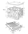
- a collapsible container generally designated by numeral 25 is shown in the various stages of assembly from beginning in Figure 1 of the drawings through completion in Figure 3 of the drawings.
- the container made according to the present invention can be of a variety of sizes; however, the unique features of the invention permit the container finally assembled according to the present invention to be a relatively large container. For instance, the container can easily be eight feet square and five feet high or larger when finally assembled. Consequently, the sides of the container are quite large but nevertheless can be assembled by a single person due to the mortise joint features adopted in the construction of the container 25.
- the mortise joints are utilized in the assembly of the sides of the container 25 to the rectangular base 21 of the container.
- the base 21 of the container 25 includes a planar support surface or platform 22 which is supported at each corner by corner legs 23.
- Middle legs 24 are positioned intermediate the corner legs 23 along the edge 27 of the support platform 22.
- Middle legs 24 are positioned at a prescribed distance from corner legs 23 so that a lift channel 26 is formed on either side of each of the middle legs 24 around the entire periphery of the base 21.
- These lift channels 26 are designed to accommodate a standard fork lift of the kind that are commonly used in warehouses to lift pallets loaded with heavy containers of materials. With channels 26 positioned about the periphery of base 21, a fork lift can approach the base 21 from any of its four sides, insert the forks into channels 26 and lift the base 21 and consequently the entire container for stacking or removal to some other area.
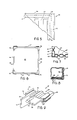
- Support platform 22 is supported in the center by a center leg which can be more clearly observed in Figure 13 of the drawings. It is noted in Figure 13 that the center leg 28 is positioned in the center of support platform 22 in order to give the platform 22 added strength when the container 25 is filled with heavy materials such as steel bolts, washers or the like. Center leg 28 is positioned in the center of platform 22 so that a fork lift can be accommodated by lift channels 26 in any direction from the edge 27 of the support platform 22.
- Platform 22 also is given additional support under the stress of heavy loads by the use of ribs 29 which might simply be a bar of added material of which the platform 22 is made or ribs 29 might be steel reinforcing rods added to the bottom surface of support platform 22 and extending between center leg 28, middle legs 24 and corner legs 23 as depicted in Figure 13 of the drawings. All of the legs 23, 24 and 28 are perpendicular to the platform or surface 22.
- ribs 29 which might simply be a bar of added material of which the platform 22 is made or ribs 29 might be steel reinforcing rods added to the bottom surface of support platform 22 and extending between center leg 28, middle legs 24 and corner legs 23 as depicted in Figure 13 of the drawings. All of the legs 23, 24 and 28 are perpendicular to the platform or surface 22.
- an edge channel is provided along the entire outside edge 27 of support platform 22.
- a mortise is located in each of the middle legs 24 and two mortises are located in each of the corner legs 23.
- Sides 33 each have tenons 34 located along a lower edge 36 of side 33.
- the tenons 34 are shaped to engage the corresponding mortise in legs 23 and 24 to form a mortise joint between side 33 and base 21.
- Figure 10 of the drawings it is noted that tenon 34 is positioned precisely within mortise 32 to provide a sturdy and secure mortise joint between the base 21 and side 23.
- the mortises 32 are perpendicular to the surface 22 and extend into each of the corner legs 23 and middle legs 24.
- an assembler may then position a first side 33 and leave it standing unsupported except through the mechanical leverage of the mortise joint formed by tenons 34 and mortises 32 and then assemble the other side 33 which is the mirror image opposite the first side 33 on the opposite side of base 21.
- the tenons 34 and mortises 32 on either side of the base 21 are identical so that sides 33 are interchangeable.
- Figure 2 of the drawings illustrates the next step in the assembly of a container according to the present invention.
- a side 37 is positioned for engagement with sides 33 and also for engagement with mortises 32 along edge 27 of base 21.
- Side 37 also is constructed with a series of tenons 38 which are designed to precisely fit mortises 32 located in corner legs 23 and center legs 24.
- Tenons 38 work exactly the same as tenons 34 and consequently the description of the function of tenons 38 is the same as that used in connection with tenons 34 as viewed in Figure 10 of the drawings.
- Tenons 38 are designed to precisely fit the mortises 32 so that side 37 is rigidly connected in a vertical position to base 21. As with sides 33, sides 37 could also be separately positioned in the base 21 through the use of a mortise joint and the individual sides 37 would be self-supporting.
- Tenons 34 and 38 are tapered. The tapered shape can be observed in Figures 1, 2 and 3 of the drawings. Likewise, mortises 32 are also tapered the same as the tenons so that the tenons 34 and 38 precisely engage mortises 32 to form a tight, rigid connection.
- Side 37 is designed to cooperate with side 33 along each edge of the sides in order to securely lock the edges of the respective sides together in a tongue and groove connection.
- Edge 39 of side 37 is a tongue element 41 which is designed to slide within channel 42 which extends along the length of edge 43 of side 33.
- Each of the sides 33 has a channel 42 extending the full length of the side 33 from the top 46 to the lower edge 36 of side 33. This channel is perpendicular to lower edge 36.
- tongue 41 extends the full length of side 37 from top 47 to lower edge 48. Tongue 41 is also perpendicular to lower edge 48.
- There is an identical tongue 41 on each edge 39 of side 37 which is designed to engage channel 42 of opposing sides 33 of the container.
- Figure 2 of the drawings illustrates side 37 partly assembled with the tongue 41 partly engaged with the channel 42 of side 33.
- the container has two identical sides 37 which again are mirror images of each other just as sides 33 are mirror images.
- the respective mirror images of 37 each have tongues 41 on each edge of the side 37 for engaging adjacent channels 42 which extend along each edge of mirror image sides 33.
- FIG. 9 of the drawings depict a perspective view of the sides 33 and 37.
- the view shows the channel or groove 42 on each edge of side 33 which cooperates with tongue 41 and which makes up each edge of side 37 to form the tongue and groove assembly for fitting sides 33 and 37 together to form the sides of the container.
- the container While the structural rigidity is achieved through the combination of tongue and groove edge fittings and a mortise joint between the sides 33 and 37 and the base 21, the container nevertheless is very rigid and will easily accommodate loads of heavy articles such as steel washers, articulate material, and even liquids under certain circumstances.
- the container 25 is lined with a liquid-proof liner such as plastic, the container 25 can be filled with a liquid and still maintain its rigidity and structural integrity.
- the collapsible container 25 is specifically designed to accommodate heavy loads of bulky material and to act as a storage container. Further, the container 25 is, because of its physical size, capable of accommodating extremely heavy loads which exert tremendous pressure on sides 33 and 37. Accordingly, an added feature of the container 25 is to provide corner caps 52 which serve a multiple function. First the corner caps 52 are attached to one set of similar sides. In the example illustrated in Figures 2 and 3 of the drawings, the corner caps 52 have been attached at the corners of sides 37 and are overlapping the tongue 41 at the intersection of tongue 41 and top 47. A more detailed view of corner cap 52 is illustrated in Figure 12 of the drawings. Corner cap 52 is a right angle or L-shaped brace which has an H cross-sectional shape as illustrated in Figure 12.
- Corner cap 52 has a flange 53 having a function which will be more specifically described hereafter.
- the cap 52 has a channel 54 which is designed to fit over edge 47 of side 37.
- One leg of the L-shaped cap 52 is positioned over a corner of side 37 as illustrated in Figure 11 of the drawings. This leg 56 is bolted to the side 37 by bolts 57 so that it remains rigidly in place and acts as a cap over the corner of side 37.
- a cap 52 is placed over each corner of side 37 as illustrated in Figure 2 of the drawings and in each case is bolted or riveted to the side 37.
- side 37 as viewed in Figure 2 of the drawings is lowered into position with tenons 38 engaging mortise 32, the second leg 58 engages the top edge 46 of the adjacent side 33 to lock the corners of sides 37 and 33 securely together.
- end cap 52 acts as a corner lock to rigidly connect the sides 33 and 37 together and to reinforce the corners of engagement between the sides.
- This locking engagement of corner cap 52 is best illustrated in Figure 3 of the drawings where sides 33 and 37 are illustrated fully in place with end caps 52 engaging adjacent sides.
- Corner cap 52 may be made of any strong material such as steel, aluminum, or similar material. A primary objective of corner cap 52 is to added reinforcement across the corners of engagement between sides 37 and 33 and to provide additional strength at the top of the assembled container.
- Corner caps 52 also serve an additional and important function.
- the flange 53 of corner caps 52 acts as a stabilizing unit so that additional containers identical to the container of this invention may be vertically stacked one on top of the other to produce a column of stacked containers for storage and warehousing of materials.
- Corner legs 23 of the container are designed so that they exactly fit within the four corner caps 52 and are securely fixed in place and prevented from moving horizontally by flange 53 of the corner cap 52. This cooperation between the flange 53 and leg 23 is best illustrated in Figure 11 of the drawings where leg 23 is shown positioned on top of corner cap 52 and retained in place by flange 53.
- a fork lift truck can merely insert the lift forks into channels 26 of a second container and position the second container over top of the first container. The second container is then lowered onto the first container positioning the corner legs 23 within the corner caps 52 and lowering the second container onto corner cap base 59.
- the container constructed according to this embodiment is sufficiently strong to withstand the weight of multiple containers bearing weight of other containers loaded with material.
- corner caps 52 also act as stays for holding a cover 61 in place on the container if the goods carried by the container are to be shielded from rain, moisture or other contamination.
- a cover 61 is molded in a shape which provide corner covers or members 62 which can be inserted over corner caps 52 to hold cover 61 in place.
- Corner covers 62 serve not only to secure cover 61 to the container, but also function the same as corner caps 52 and act as restraining members in the event that containers, all of which contain lids are stacked.
- Corner covers 62 are hollow, L-shaped extensions that fit over L-shaped corner caps 52.
- corner covers 62 After cover 61 is securely positioned over the container, with corner covers 62 in place over corner caps 52, then a second container may be lifted and positioned into place and vertically stacked upon the covered container.
- the L-shaped corner covers 62 now function exactly as corner cap 52 functioned and as earlier described to receive corner legs 23 of the container stacked immediately above and thus function the same as corner caps 52.
- Corner caps 52 provides a very important and multifunctional purpose in this container. Caps 52 lock the corners of sides 37 and 33 together, act as a stacking mechanism and act as means for securely holding a cover on top of the container 25.
- the container according to this invention can be used for a wide variety of storage purposes. Some of these storage and transportation purposes involve very heavy materials which may require reinforcement of the sides of the container. Reinforcement of this container can be accomplished very easily by adding reinforcing rods in the side walls of 33 and 37 of the container.
- the side walls 33 and 37 are already formed in a waffle pattern formed by hollow ribs 63. These ribs can be observed readily in several of the drawings.
- the support platform 22, sides 33 and 37 and the top 61 of the container are preferably made from special compositions of plastic, fiberglass, or similar materials which can be laminated, molded or injection molded to form the sides having the complex shapes illustrated in the drawings and forming ribs 63 to reinforce the sides and give the container 25 columnar strength, vertical to and lateral to the support surface 22.
- One illustration of the cross sectional shape of the sides 33 and 37 is illustrated in Figure 7 of the drawings where the ribs 63 are observed to be hollow with intermediate areas 64 joined to form a waffle construction which has proven to be structurally very strong.
- This construction may be achieved by joining sheets of moldable material at the intermediate areas 64 and joining several layers of material together at these points either by gluing, heat welding or by other well-known means, depending upon the composition of the material used to construct the container. As an example, if a thermal plastic is used, then heat at carefully controlled temperatures may be used to join the various layers of material in order to form the strong laminated waffled pattern depicted in the drawings.
- Reinforcing rods 66 and 67 can be placed in both sides 33 and 37 and function exactly the same in each side.
- the above-identified description in connection with side 33 is for illustrative purposes only.
- Horizontal reinforcing rod 67 as noted in Figure 5 of the drawings can be joined at a corner 68 with a vertical reinforcing rod 66 to add further structural rigidity to the side 33.
- As many vertical rods 66 as desired may be added to the side 33 and the number is only limited by the number of ribs 63 the side may contain. Further, the manner of adding rods 66 and 67 to the sides 33 will be governed to some extent by the manner and material used to form side 33.
- the vertical rod 66 and horizontal rod 67 may be positioned between the two laminating sheets during the formation of the sides 33.
- the rods may also be placed in the sides in an injection molding process where thermal plastics or similar materials are used to form sides 33.
- the rod 66 extends the length of side 33 and can be positioned as illustrated in Figure 9 of the drawings against a bottom ridge 69 thus transferring any load along rod 66 to the ridge 69.
- FIG. 8 of the drawings illustrates a cross section of tenons 34 and 38 of sides 33 and 37 respectively.
- a tenon rib 71 is formed in tenon 34 and is designed to exactly fit leg rib 72 so that when tenon 34 is inserted into the mortise 32, the tenon 34 will precisely and securely be fitted and held within the mortise.
- the ribs 71 and 72 add additional lateral stability to the tenon and mortise connection and also serve as a method for identifying which side is positioned.
- Tenon 38 contains a projection 73 which is different from the leg rib 71 so that it will not function as smoothly if an attempt is made to mount side 37 on the wrong side of base 21.
- Projection 73 indicates to an assembler that the side needs to be positioned on a different side of the container 25. This feature involving ribs 71 and projection 73 would be important if the container is not precisely square but is more rectangular in shape.
- the rib 71 and projection 73 will immediately indicate to a party constructing the container to reposition the particular side on a different side of the base 21.
- FIG. 4 demonstrates one of the outstanding features of the present invention.
- the container is illustrated in Figure 4 in a collapsed and nested position.
- the sides 33 and 37 of the container are specifically designed to nest one on top of the other which in turn are positioned on top of base 21 in order to provide a compact package for storage and transportation purposes.
- Sides 37 which contain corner caps 52 are designed to nest with each other as illustrated in Figure 4 so that the caps 52 of each of the sides 37 are 180 degrees apart from each other as positioned together.
- Sides 37 are then positioned over sides 33 to cover the sides 33 which are lying on support platform 22 of base 21. This entire assembly then is compactly nested and can be secured by straps 74 to secure the bundle together.
- the container 25 notably makes no use of bolts, hinges or clasps either as assembled or disassembled for the purpose of constructing a structurally strong container or for the purpose of compactly collapsing the containers.
- the materials from which the container can be constructed can vary from wood to metal to a variety of plastics.
- the plastics may be formed by injection molding, lamination of plastic sheets or similar processes.
- straps 74 designed for securing the collapsed container can also be used as illustrated in Figure 3 of the drawings to secure the sides 33 and 37 to the base 21 for additional rigidity in the container. These straps 74 are not absolutely necessary, however, if certain applications require further vertical tension to be applied to the sides 33 or 37 then straps 74 are a method by which this can be accomplished. Strap 74 interconnect base 21 with sides 33 and 37 to hold the sides together with the cooperation of the mortise joint 49.
- Corner caps 52 can take somewhat different shapes and be constructed of different kinds of material. The important features are as illustrated, namely acting as a stacking mechanism, reinforcing the corners of the adjoining sides 33 and 37 and acting as a method for securing the lid 61 to the container. These end caps 52 may be mounted in pairs either on sides 33 or 37 since the location is merely a matter of design choice.
- the container may be square or rectangular at the option of the manufacturer in order to accommodate a variety of warehousing and transportation needs.
- Ribs 71 and 72, as well as projection 73 may be used at the option of the manufacturer of the containers.
- the ribs as indicated add an additional feature to the mortise joint formed by the tenons and mortise of this container.
- the number of vertical reinforcing rods 66 placed in the sides 33 and 37 may be varied according to the strength needs and the use of the container. Addition of such reinforcing rods adds additional cost to constructing the container and additional weight to the container. Where cost and weight considerations are more important than structural strength, then these reinforcing rods 66 and 67 can be entirely eliminated from the construction of the container.
Landscapes
- Engineering & Computer Science (AREA)
- Mechanical Engineering (AREA)
- Stackable Containers (AREA)
- Rigid Containers With Two Or More Constituent Elements (AREA)
- Pallets (AREA)
Abstract
Description
- This invention relates to a collapsible container for transportation and storage of materials or parts or the like.
- Modern mass production of goods requires effective methods of supplying components to a manufacturing plant on a timely and efficient basis. These same manufacturing processes and procedures also generate a large quantity of refuse and industrial waste which also need to be removed from the manufacturing site to proper waste disposal locations or to recycling plants. These component supply needs and waste removal needs create a need for effective means for timely and constant delivery to manufacturing sites of a variety of industrial components and products. Without the timely arrival and a continuous supply of such components, mass production of finished goods rapidly encounters troublesome and inefficient production delays.
- Further, mass production techniques generate a wide variety of waste components, some of which need to be disposed of in waste disposal locations. Other kinds of waste components can be recycled. Examples of recycleable waste components might include plastic containers used for encapsulating or transporting fragile electronics components which are used in manufacture or larger electrical units. The plastic containers or carriers for these components are essentially waste products which in many cases can be reprocessed for additional or continuous use. Accumulation of these waste components create a problem for the manufacturer and requires special handling of the components and timely and continuous removal from the manufacturing site in order to avoid unmanageable build-up of waste at the manufacturing site.
- Methods for supplying components to manufacturing plants and for removing both finished goods and waste products from the manufacturing plant have been solved in a variety of ways. In some cases entire railroad cars or trucks are parked at the manufacturing site for the purpose of acting as temporary storage for components. These railroad cars and tractor trailors are extremely expensive components to have idly parked at such manufacturing plants during the course of utilizing the components. The extreme cost competitiveness involved in mass production prohibits the use of expensive containers of this type. Such transportation trailers and cars are also prohibitively expensive for collecting finished product or waste product for the same reason.
- Other methods of delivering components to manufacturing plants and for removing finished goods and waste products involve some form of container which can be delivered to the manufacturing plant and is essentially a single-use container. Examples of these single-use containers might include containers made of various types of compressed paper. Other such containers include reinforced paper containers or wooden crates. Combinations of wood and paper-type fabric also are frequently used for transporting components for manufacturing processes. Most of these wood or paper containers are destroyed or unusable for repeated use and accordingly are the source of manufacturing waste products.
- Many of the paper and wood containers are sufficiently large and laden with materials which are sufficiently heavy so that they present handling problems at the plant. These handling problems at the plant have typically been solved by the use of wooden pallets. Wood and fabric containers or other rigid containers containing heavy materials are frequently stacked on wooden pallets which have been constructed so that a forklift may be used to engage the pallet and lift the pallet and container filled with components to a location where further disposition may be made of the contents of the container.
- Again, these wooden containers and the pallets themselves also become excess materials and are frequently damaged in the process of handling the heavy containers. The pallets are made form inexpensive wood with the view that the pallets will be damaged beyond use after a limited number of usages. Nevertheless, these pallets become additional waste material for a manufacturer.
- Large containers which have been successfully used in manufacturing processes and in waste disposal procedures and which are intended for repeated use are frequently extremely large containers of sturdy construction. Many waste disposal containers, as an example, are made from thick rolled steel plates which permit rough handling of the container without destruction of the container. Many of these containers are as high as six feet tall and as large as six feet square or larger. Frequently, these sturdy large containers are also the same containers or similar to containers used for shipping components to manufacturers for use.
- Typical uses of these large containers might be involved in the supply to an electrical units manufacturer where large numbers of transistors, resistors, capacitors and other small parts are used by the manufacturer to assemble radios, televisions and similar electronic components. Resistors, as an example, might be shipped to the manufacturer in bulk in such containers and deposited at the manufacturers warehouse for use in the manufacturing process.
- The automobile industry also has a high demand for supplies of nuts, bolts, washers and similar connecting devices. Frequently these connectors are purchased in bulk from suppliers of such units. The bulk supplies are shipped from the manufacturer to the auto producer in containers which are deposited at the manufacturing warehouse or at the input line of the auto assembler.
- Other industries also use bulk supplies of products. An example in the plastics industry might include plastic pellets which are supplied to a plastics molding manufacturer. Plastic pellets having the physical characteristics required by the manufacturer or plastic parts are supplied in bulk in large containers from which the raw plastic pellets are removed and further processed in the manufacturing process.
- Likewise, bulk delivery of food products or components for food products such as flour, seasonings and similar food ingredients frequently need to be delivered to processors of packaged food products for mixing with a variety of components to produce packaged or finished food products.
- As product is removed from the bulk containers by the manufacturer, the containers either become waste product themselves or if they are of the sturdy steel-plate construction or similar construction, they become empty units which must be stored until reuse. Whether the result of the manufacturing process is generation of a large volume of waste product from the containers themselves or the presence at the manufacturing site of a large volume of empty containers, there nevertheless is created for the manufacturer a handling problem and cost and also a storage cost. The waste product must be stored until removed from the site. Likewise, any reusable containers must be handled and stored until the container can be reused. These handling costs and storage costs all add incremental costs to the cost of manufacturing the end product and therefore removal of these cost components from the cost of manufacturing is very desirable on the part of manufacturers.
- Additional problems encountered by goods transportation industries might be illustrated by the movement of household and industrial goods by transportation companies. Frequently, household goods or business goods might be packed in containers for loading on larger trucks. These containers are essentially one-way shipping units which must then be transported in an empty condition back to another site for filling with additional household goods. It is important to such transportation companies that the trucks hauling empty containers haul as many such containers as possible. Therefore, an effective and efficient collapsible container will permit such transportation companies to effectively and efficiently haul large numbers of these collapsible type containers to sites where they can be assembled for reuse. Likewise, storage of containers awaiting use can present costly warehousing if the containers cannot be collapsed to as small a unit as possible.
- There is substantial incentive for providing a container which avoids many of these problems.
- According to the invention there is provided a collapsible container for transportation and storage of materials or parts which comprises:
- A. a rectangular base having a generally planar support surface;
- B. a plurality of legs mounted about the periphery of said support surface and extending from said surface downwardly and perpendicular to said support surface;
- C. said legs having mortises extending into said legs and from the periphery of said support surface and perpendicular to said support surface;
- D. a first pair of sides having tenons extending from a bottom edge of each of said first pair of sides and for engaging the mortises in said legs to form a mortise joint to position each of said pairs of first sides in an upright position perpendicular to said support surface on opposite sides of said base
- E. a second pair of sides having tenons extending from a bottom edge of each of said second pairs of sides and for engaging the mortises in said legs to form a mortise joint to position each of said pairs of second sides in an upright position perpendicular to said support surface on opposite sides of said base and in edge to edge contact with said first sides; and,
- F. means for connecting said first and second sides in the rectangular configuration of said base.
- The invention thus provides a collapsible container having connected e.g. interlocking sides to establish a generally rectangular upstanding unit which includes a plane or base having a plurality of legs arranged to support the unit.
- Preferably the container is formed of joinable and separable sections including four sides, two of which are provided with vertical tongue elements at two edges and two of which are provided with groove elements which form a tongue and groove connection at the edges of the unit. The sides may be formed with a plurality of vertically orientated strengthening columns to provide columnar strength to the unit to permit stacking of multiple like containers. Selected sides may be provided with corner locking elements that lock the individual sides together. Each locking element may be in the form of a corner cap which functions as a corner support and as a multiple stacking support and restraining unit.
- A preferred embodiment comprises a knock down container for storage and transportation of various bulk materials which includes a base having a plurality of peripherally spaced legs with the spacing selected to permit forks of a fork lift truck or other material handling vehicle to be inserted beneath the base and between the legs for lifting the container and load. The container may thus be lifted fully loaded for warehousing or positioning at a manufacturing line assembly. A preferred embodiment has four side elements, each of which is connectable through the use of a mortise joint to a base unit and in which the mortise joint is formed as part of the legs supporting the container.
- A preferred embodiment of the invention will now be described by way of example and with reference to the accompanying drawings, in which:-
- Figure 1 is an exploded perspective view of two sides and a base of the container;
- Figure 2 is a partially exploded perspective view of a container according to the present invention showing four sides in the process of assembly on a base;
- Figure 3 is a perspective view of a collapsible container according to the present invention illustrating the container fully assembled;
- Figure 4 of the drawings is a perspective view of the container according to the present invention in the collapsed position with sides nested on a base;
- Figure 4 is partial view taken along line 5-5 of Figure 1 illustrating a corner of a side;
- Figure 6 is a planned view of the container assembled according to the present invention;
- Figure 7 is a fractional cross sectional view showing a corner connection between two sides of a container;
- Figure 8 is a cross sectional view taken along line 8-8 of Figure 3 of the drawings showing a tenon and mortise connection in a leg of the base;
- Figure 9 is a perspective fractional view showing an edge connection between adjacent sides of the container;
- Figure 10 is a fractional view in cross section illustrating a mortise joint connection;
- Figure 11 is a fractional view illustrating a corner cap connecting the sides of a container;
- Figure 12 is a perspective view of a corner cap according to the present invention; and
- Figure 13 is a plan view of a base of a container illustrating legs for supporting the container.
- Referring first to Figures 1, 2 and 3 of the drawings, a collapsible container generally designated by
numeral 25 is shown in the various stages of assembly from beginning in Figure 1 of the drawings through completion in Figure 3 of the drawings. The container made according to the present invention can be of a variety of sizes; however, the unique features of the invention permit the container finally assembled according to the present invention to be a relatively large container. For instance, the container can easily be eight feet square and five feet high or larger when finally assembled. Consequently, the sides of the container are quite large but nevertheless can be assembled by a single person due to the mortise joint features adopted in the construction of thecontainer 25. The mortise joints are utilized in the assembly of the sides of thecontainer 25 to therectangular base 21 of the container. - The
base 21 of thecontainer 25 includes a planar support surface orplatform 22 which is supported at each corner bycorner legs 23.Middle legs 24 are positioned intermediate thecorner legs 23 along theedge 27 of thesupport platform 22.Middle legs 24 are positioned at a prescribed distance fromcorner legs 23 so that alift channel 26 is formed on either side of each of themiddle legs 24 around the entire periphery of thebase 21. Theselift channels 26 are designed to accommodate a standard fork lift of the kind that are commonly used in warehouses to lift pallets loaded with heavy containers of materials. Withchannels 26 positioned about the periphery ofbase 21, a fork lift can approach the base 21 from any of its four sides, insert the forks intochannels 26 and lift thebase 21 and consequently the entire container for stacking or removal to some other area. -
Support platform 22 is supported in the center by a center leg which can be more clearly observed in Figure 13 of the drawings. It is noted in Figure 13 that thecenter leg 28 is positioned in the center ofsupport platform 22 in order to give theplatform 22 added strength when thecontainer 25 is filled with heavy materials such as steel bolts, washers or the like.Center leg 28 is positioned in the center ofplatform 22 so that a fork lift can be accommodated bylift channels 26 in any direction from theedge 27 of thesupport platform 22.Platform 22 also is given additional support under the stress of heavy loads by the use ofribs 29 which might simply be a bar of added material of which theplatform 22 is made orribs 29 might be steel reinforcing rods added to the bottom surface ofsupport platform 22 and extending betweencenter leg 28,middle legs 24 andcorner legs 23 as depicted in Figure 13 of the drawings. All of thelegs surface 22. - At the
edge 27 ofbase 21, an edge channel is provided along the entireoutside edge 27 ofsupport platform 22. A mortise is located in each of themiddle legs 24 and two mortises are located in each of thecorner legs 23.Sides 33 each have tenons 34 located along alower edge 36 ofside 33. Thetenons 34 are shaped to engage the corresponding mortise inlegs side 33 andbase 21. A more detailed view of themortise 32 and thetenon 34 is illustrated in Figure 10 of the drawings. In that drawing it is noted thattenon 34 is positioned precisely withinmortise 32 to provide a sturdy and secure mortise joint between the base 21 andside 23. Themortises 32 are perpendicular to thesurface 22 and extend into each of thecorner legs 23 andmiddle legs 24. - Again refer to Figures 1 and 2 of the drawings. Even though
side 33 and its mirror image on the other side ofbase 21 are relatively large, being several feet in each dimension, nevertheless, thetenons 34 are sufficiently long so that when theside 33 is positioned inchannel 31 with thetenons 34 securely engagingmortises 32, the mortise joint will supportside 33 in a free-standing position perpendicular to supportsurface 22. Because the mortise joint permitsside 33 to stand vertical and freely without support, this permits an assembler of the container to position one side at a time without the assistance of a second assembler. During the assembly process, an assembler may then position afirst side 33 and leave it standing unsupported except through the mechanical leverage of the mortise joint formed bytenons 34 andmortises 32 and then assemble theother side 33 which is the mirror image opposite thefirst side 33 on the opposite side ofbase 21. Thetenons 34 andmortises 32 on either side of the base 21 are identical so thatsides 33 are interchangeable. - Figure 2 of the drawings illustrates the next step in the assembly of a container according to the present invention. After
sides 33 have been firmly positioned in an upright position perpendicular to the plane of thesupport platform 22, aside 37 is positioned for engagement withsides 33 and also for engagement withmortises 32 alongedge 27 ofbase 21.Side 37 also is constructed with a series oftenons 38 which are designed to precisely fitmortises 32 located incorner legs 23 andcenter legs 24.Tenons 38 work exactly the same as tenons 34 and consequently the description of the function oftenons 38 is the same as that used in connection withtenons 34 as viewed in Figure 10 of the drawings.Tenons 38 are designed to precisely fit themortises 32 so thatside 37 is rigidly connected in a vertical position tobase 21. As withsides 33, sides 37 could also be separately positioned in the base 21 through the use of a mortise joint and theindividual sides 37 would be self-supporting. - Tenons 34 and 38 are tapered. The tapered shape can be observed in Figures 1, 2 and 3 of the drawings. Likewise, mortises 32 are also tapered the same as the tenons so that the
tenons mortises 32 to form a tight, rigid connection. -
Side 37 is designed to cooperate withside 33 along each edge of the sides in order to securely lock the edges of the respective sides together in a tongue and groove connection.Edge 39 ofside 37 is atongue element 41 which is designed to slide withinchannel 42 which extends along the length ofedge 43 ofside 33. Each of thesides 33 has achannel 42 extending the full length of theside 33 from the top 46 to thelower edge 36 ofside 33. This channel is perpendicular tolower edge 36. Likewise,tongue 41 extends the full length ofside 37 from top 47 to lower edge 48.Tongue 41 is also perpendicular to lower edge 48. There is anidentical tongue 41 on eachedge 39 ofside 37 which is designed to engagechannel 42 of opposingsides 33 of the container. - Figure 2 of the drawings illustrates
side 37 partly assembled with thetongue 41 partly engaged with thechannel 42 ofside 33. The container has twoidentical sides 37 which again are mirror images of each other just assides 33 are mirror images. The respective mirror images of 37 each havetongues 41 on each edge of theside 37 for engagingadjacent channels 42 which extend along each edge of mirror image sides 33. Thus, when sides 37 engagesides 33 through the use of the tongue and groove channel, thesides - The tongue and groove engagement described in connection with
sides sides side 33 which cooperates withtongue 41 and which makes up each edge ofside 37 to form the tongue and groove assembly for fittingsides -
Side 37 is lowered ontobase 21 so that the tongue and groove connection is fully engaged and so that thetenons 38 fully engagemortises 32 in thebase 21. Thus assembled, the container appears as illustrated in Figure 3 of the drawings. Amortise joint 49 is thus formed betweensides base 21. Since the mortise joint is sufficiently rigid and tight fitting to permit each of thesides sides edges 51 will add great structural rigidity to the container. While the structural rigidity is achieved through the combination of tongue and groove edge fittings and a mortise joint between thesides base 21, the container nevertheless is very rigid and will easily accommodate loads of heavy articles such as steel washers, articulate material, and even liquids under certain circumstances. For example, if thecontainer 25 is lined with a liquid-proof liner such as plastic, thecontainer 25 can be filled with a liquid and still maintain its rigidity and structural integrity. - The
collapsible container 25 is specifically designed to accommodate heavy loads of bulky material and to act as a storage container. Further, thecontainer 25 is, because of its physical size, capable of accommodating extremely heavy loads which exert tremendous pressure onsides container 25 is to provide corner caps 52 which serve a multiple function. First the corner caps 52 are attached to one set of similar sides. In the example illustrated in Figures 2 and 3 of the drawings, the corner caps 52 have been attached at the corners ofsides 37 and are overlapping thetongue 41 at the intersection oftongue 41 and top 47. A more detailed view ofcorner cap 52 is illustrated in Figure 12 of the drawings.Corner cap 52 is a right angle or L-shaped brace which has an H cross-sectional shape as illustrated in Figure 12.Corner cap 52 has aflange 53 having a function which will be more specifically described hereafter. Thecap 52 has achannel 54 which is designed to fit overedge 47 ofside 37. One leg of the L-shapedcap 52 is positioned over a corner ofside 37 as illustrated in Figure 11 of the drawings. This leg 56 is bolted to theside 37 bybolts 57 so that it remains rigidly in place and acts as a cap over the corner ofside 37. - A
cap 52 is placed over each corner ofside 37 as illustrated in Figure 2 of the drawings and in each case is bolted or riveted to theside 37. Whenside 37 as viewed in Figure 2 of the drawings is lowered into position withtenons 38 engagingmortise 32, the second leg 58 engages thetop edge 46 of theadjacent side 33 to lock the corners ofsides end cap 52 acts as a corner lock to rigidly connect thesides corner cap 52 is best illustrated in Figure 3 of the drawings wheresides end caps 52 engaging adjacent sides.Corner cap 52 may be made of any strong material such as steel, aluminum, or similar material. A primary objective ofcorner cap 52 is to added reinforcement across the corners of engagement betweensides - Corner caps 52 also serve an additional and important function. The
flange 53 of corner caps 52 acts as a stabilizing unit so that additional containers identical to the container of this invention may be vertically stacked one on top of the other to produce a column of stacked containers for storage and warehousing of materials.Corner legs 23 of the container are designed so that they exactly fit within the fourcorner caps 52 and are securely fixed in place and prevented from moving horizontally by flange 53 of thecorner cap 52. This cooperation between theflange 53 andleg 23 is best illustrated in Figure 11 of the drawings whereleg 23 is shown positioned on top ofcorner cap 52 and retained in place byflange 53. If the containers, according to this embodiment, are to be stacked, a fork lift truck can merely insert the lift forks intochannels 26 of a second container and position the second container over top of the first container. The second container is then lowered onto the first container positioning thecorner legs 23 within the corner caps 52 and lowering the second container ontocorner cap base 59. The container constructed according to this embodiment is sufficiently strong to withstand the weight of multiple containers bearing weight of other containers loaded with material. - Another important feature is the flexibility built into this container to function in a variety of ways. Reference to Figure 3 of the drawings will reveal that corner caps 52 also act as stays for holding a
cover 61 in place on the container if the goods carried by the container are to be shielded from rain, moisture or other contamination. In this function, acover 61 is molded in a shape which provide corner covers ormembers 62 which can be inserted over corner caps 52 to holdcover 61 in place. Corner covers 62 serve not only to securecover 61 to the container, but also function the same as corner caps 52 and act as restraining members in the event that containers, all of which contain lids are stacked. Corner covers 62 are hollow, L-shaped extensions that fit over L-shaped corner caps 52. Aftercover 61 is securely positioned over the container, with corner covers 62 in place over corner caps 52, then a second container may be lifted and positioned into place and vertically stacked upon the covered container. The L-shaped corner covers 62 now function exactly ascorner cap 52 functioned and as earlier described to receivecorner legs 23 of the container stacked immediately above and thus function the same as corner caps 52. Corner caps 52 provides a very important and multifunctional purpose in this container.Caps 52 lock the corners ofsides container 25. - The container according to this invention can be used for a wide variety of storage purposes. Some of these storage and transportation purposes involve very heavy materials which may require reinforcement of the sides of the container. Reinforcement of this container can be accomplished very easily by adding reinforcing rods in the side walls of 33 and 37 of the container. The
side walls hollow ribs 63. These ribs can be observed readily in several of the drawings. Thesupport platform 22, sides 33 and 37 and the top 61 of the container are preferably made from special compositions of plastic, fiberglass, or similar materials which can be laminated, molded or injection molded to form the sides having the complex shapes illustrated in the drawings and formingribs 63 to reinforce the sides and give thecontainer 25 columnar strength, vertical to and lateral to thesupport surface 22. One illustration of the cross sectional shape of thesides ribs 63 are observed to be hollow withintermediate areas 64 joined to form a waffle construction which has proven to be structurally very strong. This construction may be achieved by joining sheets of moldable material at theintermediate areas 64 and joining several layers of material together at these points either by gluing, heat welding or by other well-known means, depending upon the composition of the material used to construct the container. As an example, if a thermal plastic is used, then heat at carefully controlled temperatures may be used to join the various layers of material in order to form the strong laminated waffled pattern depicted in the drawings. - Further reinforcement of the
sides sides similar rods 66 may be molded into thesides rod 66 is molded or laminated into arib 63 at the time of manufacturing. Thisvertical rod 66 which is perpendicular to thesurface 22 adds columnar strength to the container and extends the length of the side from near thetop edge 46 to a position near thelower edge 36 ofside 33 as an example.Rod 66 provides vertical strength to the container so that some of the weight positioned at the corners of the container overcorner cap 52 will be transferred along the length of reinforcingrod 66 and provide added strength for stacking the containers. - Further strength in a horizontal direction may be added to the
side 33 and alsoside 37 by adding another horizontal reinforcingrod 67 horizontally along thetop edge 46 ofside 33. It should be specifically noted at this point that a horizontal reinforcingrod 67 may also be positioned in exactly the same location ofside 37 neartop edge 47. The function of these rods however is being described in connection withside 33 taken along line 55 of Figure 1 of the drawings and specifically illustrated in Figure 5. Horizontal reinforcingrod 67 adds additional horizontal strength to theside 33 in the event weight is placed at the center ofedge 46 due to stacking or other functions of the container. - Reinforcing
rods sides side 33 is for illustrative purposes only. Horizontal reinforcingrod 67 as noted in Figure 5 of the drawings can be joined at acorner 68 with a vertical reinforcingrod 66 to add further structural rigidity to theside 33. As manyvertical rods 66 as desired may be added to theside 33 and the number is only limited by the number ofribs 63 the side may contain. Further, the manner of addingrods sides 33 will be governed to some extent by the manner and material used to formside 33. For instance, if theside 33 is made in a laminating process, then thevertical rod 66 andhorizontal rod 67 may be positioned between the two laminating sheets during the formation of thesides 33. The rods may also be placed in the sides in an injection molding process where thermal plastics or similar materials are used to form sides 33. - The
rod 66 extends the length ofside 33 and can be positioned as illustrated in Figure 9 of the drawings against abottom ridge 69 thus transferring any load alongrod 66 to theridge 69. - Refer now to Figure 8 of the drawings which illustrates a cross section of
tenons sides tenon rib 71 is formed intenon 34 and is designed to exactlyfit leg rib 72 so that whentenon 34 is inserted into themortise 32, thetenon 34 will precisely and securely be fitted and held within the mortise. - The
ribs Tenon 38 contains aprojection 73 which is different from theleg rib 71 so that it will not function as smoothly if an attempt is made to mountside 37 on the wrong side ofbase 21.Projection 73 indicates to an assembler that the side needs to be positioned on a different side of thecontainer 25. Thisfeature involving ribs 71 andprojection 73 would be important if the container is not precisely square but is more rectangular in shape. Therib 71 andprojection 73 will immediately indicate to a party constructing the container to reposition the particular side on a different side of thebase 21. - Refer next to Figure 4 of the drawings which demonstrates one of the outstanding features of the present invention. The container is illustrated in Figure 4 in a collapsed and nested position. The
sides base 21 in order to provide a compact package for storage and transportation purposes.Sides 37, which contain corner caps 52 are designed to nest with each other as illustrated in Figure 4 so that thecaps 52 of each of thesides 37 are 180 degrees apart from each other as positioned together.Sides 37 are then positioned oversides 33 to cover thesides 33 which are lying onsupport platform 22 ofbase 21. This entire assembly then is compactly nested and can be secured bystraps 74 to secure the bundle together. - The
container 25 notably makes no use of bolts, hinges or clasps either as assembled or disassembled for the purpose of constructing a structurally strong container or for the purpose of compactly collapsing the containers. - The above illustrated and described preferred embodiment of the invention may be altered in a variety of ways and still remain within the scope of the invention. As previously noted, the materials from which the container can be constructed can vary from wood to metal to a variety of plastics. In the case of plastics, the plastics, may be formed by injection molding, lamination of plastic sheets or similar processes. Further, straps 74 designed for securing the collapsed container can also be used as illustrated in Figure 3 of the drawings to secure the
sides base 21 for additional rigidity in the container. Thesestraps 74 are not absolutely necessary, however, if certain applications require further vertical tension to be applied to thesides Strap 74interconnect base 21 withsides mortise joint 49. - Corner caps 52 can take somewhat different shapes and be constructed of different kinds of material. The important features are as illustrated, namely acting as a stacking mechanism, reinforcing the corners of the adjoining
sides lid 61 to the container. These end caps 52 may be mounted in pairs either onsides -
Ribs projection 73 may be used at the option of the manufacturer of the containers. The ribs as indicated add an additional feature to the mortise joint formed by the tenons and mortise of this container. The number of vertical reinforcingrods 66 placed in thesides rods
Claims (15)
Applications Claiming Priority (2)
| Application Number | Priority Date | Filing Date | Title |
|---|---|---|---|
| US34027 | 1987-04-03 | ||
| US07/034,027 US4809851A (en) | 1987-04-03 | 1987-04-03 | Collapsible container |
Publications (2)
| Publication Number | Publication Date |
|---|---|
| EP0286271A2 true EP0286271A2 (en) | 1988-10-12 |
| EP0286271A3 EP0286271A3 (en) | 1989-06-07 |
Family
ID=21873852
Family Applications (1)
| Application Number | Title | Priority Date | Filing Date |
|---|---|---|---|
| EP88302540A Ceased EP0286271A3 (en) | 1987-04-03 | 1988-03-23 | Collapsible container |
Country Status (5)
| Country | Link |
|---|---|
| US (1) | US4809851A (en) |
| EP (1) | EP0286271A3 (en) |
| JP (1) | JPS6423944A (en) |
| KR (1) | KR880012454A (en) |
| AU (2) | AU1416988A (en) |
Cited By (19)
| Publication number | Priority date | Publication date | Assignee | Title |
|---|---|---|---|---|
| EP0510353A3 (en) * | 1991-04-25 | 1993-07-14 | Streich Sen., Roland | Collapsible cargo holder or container |
| WO1994016954A1 (en) * | 1993-01-30 | 1994-08-04 | Theodor Lentjes | Dismountable packaging unit |
| FR2751618A1 (en) * | 1996-07-24 | 1998-01-30 | Siraga Sa | Dismantlable rack for the storage and transport of bottles |
| WO2000061881A1 (en) * | 1999-04-10 | 2000-10-19 | Peter Anthony Manning | Flat pack water butt |
| FR2805521A1 (en) * | 2000-02-29 | 2001-08-31 | Bois Ouvres Du Gatinais Soc D | Collapsible crate for machine parts, fruit or vegetables is made up of pallet and four walls which fit into triangular brackets mounted on pallet with channels to accommodate lower corners of walls, similar brackets fitting over top corners |
| WO2003043900A1 (en) * | 2001-10-12 | 2003-05-30 | Uni-Logi Consolidators, Inc. | Collapsible container |
| EP1500610A3 (en) * | 2003-07-22 | 2005-08-10 | Phoenicia America-Israel (Flat Glass) Ltd. | Modified shipping container |
| EP1616803A1 (en) * | 1999-12-28 | 2006-01-18 | Arca Systems AB | Collapsible bulk container |
| WO2006091609A2 (en) | 2005-02-24 | 2006-08-31 | Packaging Engineering, Llc | Reusable container |
| FR2913008A1 (en) * | 2007-02-27 | 2008-08-29 | Rehau Sa | Plastic panel for forming wall of e.g. cubical shaped container, has hollow piece with receiving site extending between lateral edges of panel and receiving elongated reinforcement element that stiffens and rigidifies adapted section |
| WO2008122074A1 (en) * | 2007-04-05 | 2008-10-16 | Smartcage Pty Ltd | Intermodal air cargo containers |
| FR2966439A1 (en) * | 2010-10-21 | 2012-04-27 | Groupe Dusogat | Corner bead i.e. lower corner bead for assembling side walls of lattice-walled body shell used for containing screw driver, has outer outgrowth provided with rim for hooking tensile element to assemble corner bead with upper corner bead |
| FR2967976A1 (en) * | 2010-11-29 | 2012-06-01 | Groupe Dusogat | Corner bead i.e. lower corner bead for assembling side walls of lattice-walled body shell used for containing screw driver, has outer outgrowth provided with rim for hooking tensile element to assemble corner bead with upper corner bead |
| EP2492205A1 (en) * | 2011-02-22 | 2012-08-29 | Dr. Doll Holding GmbH | Insert ring for a pallet box and pallet box |
| ES2397035A1 (en) * | 2011-06-14 | 2013-03-04 | Casiano SANTANA RUIBAL | Removable container. (Machine-translation by Google Translate, not legally binding) |
| EP2894107A1 (en) * | 2014-01-10 | 2015-07-15 | PANOPACK (Société par Actions Simplifiée) | Dismountable box pallet |
| EP3508810A1 (en) * | 2018-01-09 | 2019-07-10 | Allied Tube & Conduit Corporation | Razor wire barrier for access point security |
| WO2020112794A1 (en) * | 2018-11-27 | 2020-06-04 | Integrated Composite Products, Inc. | Bin, bin assembly and kit |
| US12071274B2 (en) | 2019-10-15 | 2024-08-27 | Richard ANECK-HAHN | Modular produce crate |
Families Citing this family (141)
| Publication number | Priority date | Publication date | Assignee | Title |
|---|---|---|---|---|
| GB2216876B (en) * | 1988-04-08 | 1992-03-18 | Lin Pac Mouldings | A frame structure |
| USD314655S (en) | 1988-09-30 | 1991-02-12 | Hosmer Jimmy D | Storage and shipping container |
| US5263701A (en) * | 1988-10-24 | 1993-11-23 | Am International Incorporated | Collapsable container for stacks of sheet material |
| US4969567A (en) * | 1988-10-28 | 1990-11-13 | Vacu-Purg, Inc. | Collapsible cheese box |
| US5161709A (en) * | 1989-01-30 | 1992-11-10 | World Container Corporation | Hinged collapsible container |
| AU5241890A (en) * | 1989-04-07 | 1990-10-11 | Janssens Industries Limited | Pallets |
| US4936476A (en) * | 1989-04-20 | 1990-06-26 | Stanley Aviation Corporation | Extrusion for container with integral pallet |
| US5146732A (en) * | 1989-10-26 | 1992-09-15 | Resource America, Inc. | Recycle shipping assembly |
| US5131212A (en) * | 1989-10-26 | 1992-07-21 | Resource America, Inc. | Recycle shipping assembly |
| US5247747A (en) * | 1989-10-26 | 1993-09-28 | Resource America, Inc. | Recycle shipping container |
| US5215205A (en) * | 1989-11-09 | 1993-06-01 | Behlman David M | Article organizer |
| US5070577A (en) * | 1990-02-09 | 1991-12-10 | World Container Corporation | Seperable hinge |
| WO1992005078A1 (en) * | 1990-09-25 | 1992-04-02 | Dimitri Tosevski | A foldable container |
| US5086927A (en) * | 1990-12-06 | 1992-02-11 | Reynolds Consumer Products, Inc. | Pallet for heavy loads |
| US5036979A (en) * | 1990-12-21 | 1991-08-06 | Selz John C | Collapsible container |
| EP0521126A4 (en) * | 1991-01-17 | 1993-09-08 | Comalco Aluminium Limited | Pallet |
| JPH0814423B2 (en) * | 1991-02-04 | 1996-02-14 | タカラスタンダード株式会社 | Boiling controller for electric water heater |
| US5248051A (en) * | 1992-02-21 | 1993-09-28 | Rosby Corporation | Larger cubic volume cargo container |
| USD345847S (en) | 1992-03-09 | 1994-04-05 | Reynolds Packing Co., dba Quality Bin Co. | Collapsible bin |
| US5170933A (en) * | 1992-05-04 | 1992-12-15 | Perry Thomas J | Reusable air freight container assembly |
| US5318219A (en) * | 1992-06-05 | 1994-06-07 | Four M Manufacturing Group Of Cpc, Inc. | Collapsible pallet mounted container |
| US5236099A (en) * | 1992-08-19 | 1993-08-17 | Fties Youssef A | Plastic knockdown bin-pallet for loading, transporting and storing fruits, vegetables, fish or other foods |
| US5419448A (en) * | 1993-01-19 | 1995-05-30 | Watson; John | Knock down bulk storage container |
| US5328048A (en) * | 1993-02-08 | 1994-07-12 | Otto Industries, Inc. | Tote box |
| JPH07823U (en) * | 1993-06-03 | 1995-01-06 | キムラユニティー株式会社 | Prefabricated container |
| US5310063A (en) * | 1993-07-30 | 1994-05-10 | Skolasinski Lauraine K | Pallet display apparatus |
| US5548972A (en) * | 1993-09-10 | 1996-08-27 | Temp Top Container Systems, Inc. | Floating insulator top for pallet sized container |
| WO1995010681A1 (en) * | 1993-10-13 | 1995-04-20 | Temp Top Container Systems, Inc. | Fingered latch for pallet-sized |
| US5601202A (en) * | 1994-01-06 | 1997-02-11 | Temp Top Container Systems, Inc. | Transport chamber |
| US5558241A (en) * | 1994-01-06 | 1996-09-24 | Temp Top Container Systems, Inc. | Cryotransport chamber |
| JP2861785B2 (en) * | 1994-02-15 | 1999-02-24 | 日本電気株式会社 | Method for forming wiring of semiconductor device |
| US5542541A (en) * | 1994-08-31 | 1996-08-06 | Four M Manufacturing Group Of Cpc, Inc. | Multi-sided collapsible container |
| US5730295A (en) * | 1994-11-02 | 1998-03-24 | T.H.E.M. International, Inc. | Pallet system including end panels |
| USD370344S (en) | 1994-11-02 | 1996-06-04 | Samsung Corporation | Box |
| US5641068A (en) * | 1995-06-15 | 1997-06-24 | Hewlett-Packard Company | Adjustable and reusable protective packaging system |
| GB2330826B (en) * | 1995-07-26 | 2000-02-16 | Mckechnie Uk Ltd | Collapsible container |
| GB2303616B (en) * | 1995-07-26 | 1999-09-15 | Mckechnie Uk Ltd | Collapsible container |
| GB2340485B (en) * | 1996-03-22 | 2000-08-23 | Mckechnie Uk Ltd | Containers |
| FR2746896B1 (en) * | 1996-03-26 | 1998-06-12 | Pavailler Equipement Sa | MODULAR STRUCTURE FOR THE ESTABLISHMENT OF AN ENCLOSURE |
| US5638973A (en) * | 1996-05-09 | 1997-06-17 | Western Poly Corporation | Storage container with interlocking corner members |
| US5803295A (en) * | 1996-05-15 | 1998-09-08 | Tussey; Brian C. | Cargo carrier system |
| US5704508A (en) * | 1996-09-19 | 1998-01-06 | K-D Container L.L.C. | Interlocking shipping container |
| US5865315A (en) * | 1997-01-06 | 1999-02-02 | Uitz; Mark O | Material transport system |
| DE19700781A1 (en) * | 1997-01-11 | 1998-07-16 | Guenter Richter | Device for protecting a large-volume container and method for its production |
| US5829595A (en) * | 1997-03-03 | 1998-11-03 | Trienda Corporation | Thin sheet thermoformed pallet sleeve |
| US5953858A (en) * | 1997-08-22 | 1999-09-21 | Amaroo Enterprises, Inc. | Collapsible plastic planter box |
| US6029839A (en) * | 1998-08-05 | 2000-02-29 | Mansouri; Hossein | Collapsible shipping container |
| US5996828A (en) * | 1998-10-09 | 1999-12-07 | Cheyn; Ruey Chyuan | Corner assembly for a box |
| US6021916A (en) * | 1998-11-05 | 2000-02-08 | Stolzman; Michael D. | Plastic pallet bin |
| US6266972B1 (en) * | 1998-12-07 | 2001-07-31 | Vesture Corporation | Modular freezer pallet and method for storing perishable items |
| US6170689B1 (en) | 1999-12-16 | 2001-01-09 | Apogee Designs, Ltd. | Collapsible container |
| US6142329A (en) | 2000-01-31 | 2000-11-07 | Dolav Dvir Lahav Plastic Products | Knock-down bin |
| US20030209549A1 (en) * | 2000-07-07 | 2003-11-13 | Grimes David G. | Garbage can with removable bottom |
| US6450123B1 (en) * | 2000-07-30 | 2002-09-17 | Bennie Murray | Portable, expandable, rectilinear pet corral or enclosure |
| US7004344B2 (en) * | 2000-08-29 | 2006-02-28 | Tolko Industries Ltd. | Collapsible bin |
| KR20020036511A (en) * | 2000-11-10 | 2002-05-16 | 김재욱 | The container with multi function |
| US6634541B1 (en) * | 2001-03-22 | 2003-10-21 | James D. Hankey | Method of manufacturing metal containers |
| US20020139798A1 (en) * | 2001-03-30 | 2002-10-03 | Worthington Steelpac Systems | Shipping pallet |
| SE0103332D0 (en) * | 2001-10-04 | 2001-10-04 | Arca Systems Ab | Collapsible container for transport and storage |
| US8109402B2 (en) * | 2001-10-04 | 2012-02-07 | Schoeller Arca Systems Ab | Collapsible container for transport and storage |
| US6966449B2 (en) * | 2003-01-02 | 2005-11-22 | The Little Tikes Company | Bulk box |
| US20040139924A1 (en) * | 2003-01-22 | 2004-07-22 | Hannon Lawrence E. | Animal pen system |
| US7028859B2 (en) * | 2003-04-08 | 2006-04-18 | Suncast Corporation | Deck storage box |
| US7204397B2 (en) * | 2003-04-28 | 2007-04-17 | Deere & Company | Cargo container attachment |
| US20050167308A1 (en) * | 2004-02-04 | 2005-08-04 | Darby Robert J. | Palletless packaging system |
| US20060030254A1 (en) * | 2004-08-03 | 2006-02-09 | Norris William G Jr | Storage unit for being portable towable, liftable, rackable, and weatherproof |
| US7757876B1 (en) | 2005-05-03 | 2010-07-20 | Material Improvements, LP | Collapsible cheese container |
| US8235217B2 (en) * | 2005-05-24 | 2012-08-07 | Stolzman Michael D | Bulk container with cap and pallet base |
| US20070101646A1 (en) * | 2005-11-07 | 2007-05-10 | Licht Jeff L | Modular planter system |
| KR100639398B1 (en) | 2006-02-24 | 2006-10-31 | 전일목재산업 주식회사 | Prefabricated Packing Box for Palletizer |
| US8002134B2 (en) * | 2006-04-20 | 2011-08-23 | Cakeboxx, Llc | Doorless intermodal cargo container |
| US7422124B2 (en) * | 2006-05-05 | 2008-09-09 | Norris Jr William G | Stacking pocket for disposing at a corner of a roof of a shipping container and for holding a caster wheel of an above-stacked shipping container |
| US20080083765A1 (en) * | 2006-10-05 | 2008-04-10 | Robert Lee Landsinger | Portable container for assembly at point of use |
| TW200819357A (en) * | 2006-10-20 | 2008-05-01 | Innolux Display Corp | Cassette |
| US20080135566A1 (en) * | 2006-12-07 | 2008-06-12 | Sunbelts Cad, Llc | Method and apparatus for containing and removing construction debris |
| US8016145B2 (en) * | 2006-12-12 | 2011-09-13 | Plastic Systems, Inc. | Collapsible bulk container |
| US20080190922A1 (en) * | 2007-02-08 | 2008-08-14 | Kraeling Brett B | Collapsible shipping container |
| USD610001S1 (en) * | 2007-02-23 | 2010-02-16 | Mcalpine Gilroy Clements | Container with removable drawer |
| USD611342S1 (en) * | 2007-02-23 | 2010-03-09 | Mcalpine Gilroy Clements | Container |
| US8028849B2 (en) * | 2007-05-14 | 2011-10-04 | Packaging Engineering Llc | Reusable container |
| KR100870910B1 (en) * | 2007-07-05 | 2008-11-28 | 유한회사 경성산업 | Container for onion storage |
| IL186787A0 (en) * | 2007-10-18 | 2008-02-09 | Polymer Logistics Ltd | Foldable crate with bidirectional manually releasable latch mechanism |
| US8061538B2 (en) * | 2007-12-13 | 2011-11-22 | Philip Seldon | Wine rack |
| US20090183785A1 (en) * | 2008-01-22 | 2009-07-23 | Cole Louis F | Modular sump pump pit assembly |
| US20100018966A1 (en) * | 2008-06-10 | 2010-01-28 | You Crate Llc | Collapsible Containers |
| SE533316C2 (en) * | 2008-07-24 | 2010-08-24 | Schoeller Arca Systems Ab | transport Packaging |
| DE102008047857A1 (en) * | 2008-09-18 | 2010-04-08 | Schoeller Arca Systems Gmbh | large containers |
| US20100175596A1 (en) * | 2009-01-14 | 2010-07-15 | John Scheetz | Collapsible bulk storage pallet assembly |
| US20100282136A1 (en) * | 2009-05-08 | 2010-11-11 | Robert Stanley | Portable vault |
| US8342356B2 (en) * | 2010-03-31 | 2013-01-01 | All Source Security Container Manufacturing Corp. | Document console |
| JP5551544B2 (en) * | 2010-08-18 | 2014-07-16 | 三甲株式会社 | Assembly / disassembly container |
| US8887914B2 (en) | 2010-10-28 | 2014-11-18 | Arrows Up, Inc. | Bulk material shipping container |
| US8616370B2 (en) | 2010-10-28 | 2013-12-31 | Arrows Up, Inc. | Bulk material shipping container |
| US8689992B2 (en) | 2011-02-03 | 2014-04-08 | Suncast Technologies, Llc | Wood and resin deck box |
| US9149099B2 (en) | 2011-04-07 | 2015-10-06 | DRC Recreational Supplies LLC | Portable storage enclosure with sliding doors |
| KR101308147B1 (en) * | 2011-11-14 | 2013-09-12 | 주식회사 이엔시스템 | Assembly Protection Barrier For Septic Tank |
| US8978912B1 (en) | 2012-03-19 | 2015-03-17 | Response Holdings Corporation | Collapsible shipping tote |
| KR200467998Y1 (en) * | 2012-04-18 | 2013-07-16 | 유만길 | Pallet box for loading goods |
| CN102633033A (en) * | 2012-04-23 | 2012-08-15 | 天津晟威蜂窝纸品包装有限公司 | Joggle joint formed detachable honeycomb paperboard package box and manufacturing method thereof |
| CN103863721A (en) * | 2012-12-12 | 2014-06-18 | 鸿富锦精密工业(深圳)有限公司 | Method for packaging and transferring televisions |
| US9371179B2 (en) * | 2013-01-17 | 2016-06-21 | Buckhorn, Inc. | Collapsible nestable container |
| US9332814B2 (en) * | 2013-03-15 | 2016-05-10 | Barbara Brock | Compact organizer for cosmetics |
| CN103395540A (en) * | 2013-08-23 | 2013-11-20 | 常熟市东方新型包装材料有限公司 | Multifunctional log III-shaped pallet |
| CN103395543A (en) * | 2013-08-23 | 2013-11-20 | 常熟市东方新型包装材料有限公司 | Multifunctional strip-type artificial pallet |
| CA2930407C (en) * | 2013-11-11 | 2017-05-30 | Suncast Technologies, Llc | Blow molded resin furniture having a stabilizing box structure |
| US9557209B2 (en) * | 2013-12-02 | 2017-01-31 | Apex Industrial Technologies Llc | Load cell bin system |
| US20150321443A1 (en) * | 2014-05-06 | 2015-11-12 | Emballages Cre-O-Pack Canada Inc. | Sandwich panel, container made of such a sandwich panel and method of manufacturing the same |
| GB201409689D0 (en) * | 2014-05-30 | 2014-07-16 | Softbox Systems Ltd | A Transport and storage System |
| US9938066B2 (en) * | 2014-09-12 | 2018-04-10 | Sonoco Development, Inc. | Temperature controlled pallet shipper |
| US10479552B2 (en) * | 2015-03-06 | 2019-11-19 | Orbis Corporation | Plastic container with lift handle for fork truck transport |
| US9920512B1 (en) | 2015-05-12 | 2018-03-20 | Cakeboxx Technologies, Llc | Transformation of shipping containers to two level buildings |
| CN204812489U (en) * | 2015-07-22 | 2015-12-02 | 徐忠浪 | Suitcase cornerite device and suitcase |
| US10816257B2 (en) * | 2015-10-13 | 2020-10-27 | Danby Products Limited | Refrigeration apparatus |
| US10377563B1 (en) | 2015-11-24 | 2019-08-13 | Cakeboxx Technologies, Llc | Two-piece shipping container with vertical locking system |
| US10518823B1 (en) | 2016-01-06 | 2019-12-31 | Cakeboxx Technologies, Llc | Two piece shipping container as covered flatbed trailer |
| US20180194532A1 (en) * | 2016-02-02 | 2018-07-12 | Sonoco Development, Inc. | Temperature Controlled Pallet Shipper |
| CH712117A1 (en) * | 2016-02-12 | 2017-08-15 | Alpla Werke Alwin Lehner Gmbh & Co Kg | Tray or storage and transport container for plastic containers. |
| CN105819064B (en) * | 2016-04-19 | 2018-10-12 | 上海鸿研物流技术有限公司 | Collapsible container |
| CA2945454C (en) | 2016-06-30 | 2023-11-07 | Arrows Up, Llc | Bulk material shipping container |
| US9701466B1 (en) | 2016-07-01 | 2017-07-11 | ASR Holding Company | Construction material transport container for new material delivery and used material removal |
| DE102016010397A1 (en) * | 2016-08-30 | 2018-03-01 | Rudolf Graf | intermediate bulk containers |
| US10737830B1 (en) | 2017-02-01 | 2020-08-11 | Anthony Raul Arriaga | Washable trash container with interlocking panels |
| CA2964816A1 (en) * | 2017-04-20 | 2018-10-20 | Scott Warren Dauphinee | Lobster trap |
| GB201707922D0 (en) | 2017-05-17 | 2017-06-28 | Ocado Innovation Ltd | Modular storage systems and methods |
| US10273070B2 (en) | 2017-05-19 | 2019-04-30 | Paper Systems, Inc. | Collapsible container |
| US10532853B2 (en) * | 2018-01-05 | 2020-01-14 | Easy Gardener Products, Inc. | Product display container |
| US20190374848A1 (en) * | 2018-06-08 | 2019-12-12 | Jeffrey A. Guldin | Board Game Cover |
| US11299862B1 (en) * | 2018-08-29 | 2022-04-12 | Studio5051, Llc | Portable street planter |
| US11661235B2 (en) | 2018-10-15 | 2023-05-30 | Sandbox Enterprises, Llc | Bulk material shipping container top wall assembly and bulk material shipping container having a top wall assembly |
| US10926940B2 (en) | 2018-11-20 | 2021-02-23 | Sandbox Enterprises, Llc | Bulk material shipping container |
| US10871306B2 (en) * | 2019-01-02 | 2020-12-22 | Johnson Controls Technology Company | Modular drain pans for HVAC systems |
| JP6745380B1 (en) * | 2019-04-26 | 2020-08-26 | カンノ・トレーディング株式会社 | Decorative box body that can be assembled and disassembled freely |
| CN110589046A (en) * | 2019-09-25 | 2019-12-20 | 北京鸿通供应链管理有限公司 | Goods shelf for container and container goods loading method |
| USD971511S1 (en) * | 2020-10-21 | 2022-11-29 | EZwhelp, Inc. | Animal whelping box |
| US12378035B1 (en) * | 2020-11-25 | 2025-08-05 | Frank Joseph Tortorella, JR. | Pallet system |
| CN113772215B (en) * | 2021-09-18 | 2023-01-13 | 安庆市曙光包装有限责任公司 | Storage logistics box, storage system and loading and unloading method |
| US11464174B1 (en) | 2021-11-30 | 2022-10-11 | Nick Suteerawanit | Disassemblable planter box |
| TWD239108S (en) * | 2022-09-12 | 2025-07-01 | 聯府塑膠股份有限公司 苗栗縣銅鑼鄉銅鑼村自強路18號 (中華民國) | Storage box side panel |
| CN115248015B (en) * | 2022-09-23 | 2022-12-06 | 四川鑫跃鑫科学仪器有限公司 | A device for non-destructive testing of buried pipelines |
| KR102643545B1 (en) * | 2022-11-15 | 2024-03-04 | 윤여문 | Pallet for prefabricated container |
| CN118145162B (en) * | 2024-03-21 | 2025-08-26 | 苏州华誉智能科技有限公司 | A simple solder paste first-in-first-out fool-proof device and method |
Family Cites Families (29)
| Publication number | Priority date | Publication date | Assignee | Title |
|---|---|---|---|---|
| US1114321A (en) * | 1913-03-31 | 1914-10-20 | Alfred Warne | Folding trunk. |
| US1355213A (en) * | 1920-02-17 | 1920-10-12 | Roneo Ltd | Metal case for containing drawers, shelves, or the like |
| US1991965A (en) * | 1933-08-19 | 1935-02-19 | William J Steinbreder | Receptacle |
| US2202675A (en) * | 1939-02-25 | 1940-05-28 | Pittsburgh Plate Glass Co | Acidproof container |
| US2952379A (en) * | 1955-09-12 | 1960-09-13 | Clifford S Potter | Collapsible containers |
| US2978136A (en) * | 1958-06-10 | 1961-04-04 | Westinghouse Electric Corp | Laminated panel cabinet structure |
| US3266656A (en) * | 1964-01-02 | 1966-08-16 | Charles E Kridle | Demountable shipping case |
| US3288319A (en) * | 1964-08-20 | 1966-11-29 | Edward P Cahill | Collapsible container |
| US3315800A (en) * | 1964-12-14 | 1967-04-25 | Hampton R Wagner | Collapsible plywood shipping device |
| US3397496A (en) * | 1965-02-04 | 1968-08-20 | K & Associates Inc As | Locking means for roof and wall panel construction |
| US3332319A (en) * | 1965-06-28 | 1967-07-25 | Martin E Gerry | Sound synchronized projector devices |
| US3386218A (en) * | 1966-06-08 | 1968-06-04 | Elwin G Smith & Co Inc | Building panel with ribbed sealing element between overlapping edges |
| US3374915A (en) * | 1966-07-21 | 1968-03-26 | Verhein Donald | Collapsible and stackable container |
| US3655087A (en) * | 1970-01-29 | 1972-04-11 | Gentex Corp | Lightweight knockdown container |
| FR2128054A1 (en) * | 1971-03-02 | 1972-10-20 | Papeteries De Lumbres | Expanded polystyrene pallet - which supports the sidewalls of a cardboard pack |
| US3797691A (en) * | 1972-05-10 | 1974-03-19 | Lockheed Aircraft Corp | Modular cargo container for transport vehicles |
| US3853238A (en) * | 1972-09-05 | 1974-12-10 | Gentex Corp | Smooth operating cargo box |
| US4050604A (en) * | 1974-07-22 | 1977-09-27 | Flanders Robert D | Disassembleable, reusable container |
| US3940007A (en) * | 1974-10-22 | 1976-02-24 | Aubrey Ronald Griffiths | Containers |
| US3974616A (en) * | 1974-12-09 | 1976-08-17 | Maxwell David Beckley | Structural component for forming load supporting frames |
| DE2520519C3 (en) * | 1975-05-07 | 1978-05-03 | Siemens Ag, 1000 Berlin Und 8000 Muenchen | Stackable packaging container |
| FR2355482A1 (en) * | 1975-10-31 | 1978-01-20 | Krieg & Zivy Ind | MOUNTING DRAWER |
| US4000827A (en) * | 1976-01-09 | 1977-01-04 | Anthony Emery | Produce container |
| DE2730445C2 (en) * | 1977-07-06 | 1982-05-06 | Continental Gummi-Werke Ag, 3000 Hannover | Stackable pallet |
| DE2926976C2 (en) * | 1979-07-04 | 1982-12-30 | Rudolf 4100 Duisburg Schaefer | Body that can be assembled from individual elements |
| SE438651B (en) * | 1982-05-26 | 1985-04-29 | Kaj Hakan Andersson | Transport Case |
| FR2554086A1 (en) * | 1983-10-28 | 1985-05-03 | Delettrez Jean | Improved prefabricated package |
| US4673087A (en) * | 1985-11-04 | 1987-06-16 | Peninsula Plastics Co., Inc. | Collapsable, reusable container system |
| US4643314A (en) * | 1986-05-27 | 1987-02-17 | Chrysler Motors Corporation | Container construction |
-
1987
- 1987-04-03 US US07/034,027 patent/US4809851A/en not_active Expired - Fee Related
-
1988
- 1988-03-23 EP EP88302540A patent/EP0286271A3/en not_active Ceased
- 1988-04-01 KR KR1019880003687A patent/KR880012454A/en not_active Withdrawn
- 1988-04-04 JP JP63082877A patent/JPS6423944A/en active Pending
- 1988-04-05 AU AU14169/88A patent/AU1416988A/en not_active Abandoned
-
1991
- 1991-12-02 AU AU88368/91A patent/AU8836891A/en not_active Abandoned
Cited By (25)
| Publication number | Priority date | Publication date | Assignee | Title |
|---|---|---|---|---|
| EP0510353A3 (en) * | 1991-04-25 | 1993-07-14 | Streich Sen., Roland | Collapsible cargo holder or container |
| US5289933A (en) * | 1991-04-25 | 1994-03-01 | Roland Streich | Collapsible cargo container |
| WO1994016954A1 (en) * | 1993-01-30 | 1994-08-04 | Theodor Lentjes | Dismountable packaging unit |
| FR2751618A1 (en) * | 1996-07-24 | 1998-01-30 | Siraga Sa | Dismantlable rack for the storage and transport of bottles |
| WO2000061881A1 (en) * | 1999-04-10 | 2000-10-19 | Peter Anthony Manning | Flat pack water butt |
| GB2352266A (en) * | 1999-04-10 | 2001-01-24 | Peter Anthony Manning | Flat pack water butt |
| GB2352266B (en) * | 1999-04-10 | 2003-06-04 | Peter Anthony Manning | Water butt |
| EP1616803A1 (en) * | 1999-12-28 | 2006-01-18 | Arca Systems AB | Collapsible bulk container |
| FR2805521A1 (en) * | 2000-02-29 | 2001-08-31 | Bois Ouvres Du Gatinais Soc D | Collapsible crate for machine parts, fruit or vegetables is made up of pallet and four walls which fit into triangular brackets mounted on pallet with channels to accommodate lower corners of walls, similar brackets fitting over top corners |
| WO2003043900A1 (en) * | 2001-10-12 | 2003-05-30 | Uni-Logi Consolidators, Inc. | Collapsible container |
| EP1500610A3 (en) * | 2003-07-22 | 2005-08-10 | Phoenicia America-Israel (Flat Glass) Ltd. | Modified shipping container |
| WO2006091609A3 (en) * | 2005-02-24 | 2007-02-22 | Packaging Engineering Llc | Reusable container |
| WO2006091609A2 (en) | 2005-02-24 | 2006-08-31 | Packaging Engineering, Llc | Reusable container |
| FR2913008A1 (en) * | 2007-02-27 | 2008-08-29 | Rehau Sa | Plastic panel for forming wall of e.g. cubical shaped container, has hollow piece with receiving site extending between lateral edges of panel and receiving elongated reinforcement element that stiffens and rigidifies adapted section |
| WO2008122074A1 (en) * | 2007-04-05 | 2008-10-16 | Smartcage Pty Ltd | Intermodal air cargo containers |
| FR2966439A1 (en) * | 2010-10-21 | 2012-04-27 | Groupe Dusogat | Corner bead i.e. lower corner bead for assembling side walls of lattice-walled body shell used for containing screw driver, has outer outgrowth provided with rim for hooking tensile element to assemble corner bead with upper corner bead |
| FR2967976A1 (en) * | 2010-11-29 | 2012-06-01 | Groupe Dusogat | Corner bead i.e. lower corner bead for assembling side walls of lattice-walled body shell used for containing screw driver, has outer outgrowth provided with rim for hooking tensile element to assemble corner bead with upper corner bead |
| EP2492205A1 (en) * | 2011-02-22 | 2012-08-29 | Dr. Doll Holding GmbH | Insert ring for a pallet box and pallet box |
| ES2397035A1 (en) * | 2011-06-14 | 2013-03-04 | Casiano SANTANA RUIBAL | Removable container. (Machine-translation by Google Translate, not legally binding) |
| EP2894107A1 (en) * | 2014-01-10 | 2015-07-15 | PANOPACK (Société par Actions Simplifiée) | Dismountable box pallet |
| FR3016350A1 (en) * | 2014-01-10 | 2015-07-17 | Panopack | DISMOUNTABLE PALLET |
| EP3508810A1 (en) * | 2018-01-09 | 2019-07-10 | Allied Tube & Conduit Corporation | Razor wire barrier for access point security |
| US11066845B2 (en) | 2018-01-09 | 2021-07-20 | Allied Tube & Conduit Corporation | Razor wire barrier for access point security |
| WO2020112794A1 (en) * | 2018-11-27 | 2020-06-04 | Integrated Composite Products, Inc. | Bin, bin assembly and kit |
| US12071274B2 (en) | 2019-10-15 | 2024-08-27 | Richard ANECK-HAHN | Modular produce crate |
Also Published As
| Publication number | Publication date |
|---|---|
| JPS6423944A (en) | 1989-01-26 |
| AU1416988A (en) | 1988-10-06 |
| US4809851A (en) | 1989-03-07 |
| EP0286271A3 (en) | 1989-06-07 |
| KR880012454A (en) | 1988-11-26 |
| AU8836891A (en) | 1992-01-23 |
Similar Documents
| Publication | Publication Date | Title |
|---|---|---|
| US4809851A (en) | Collapsible container | |
| US5161709A (en) | Hinged collapsible container | |
| US9169040B2 (en) | Nestable pallet and stackable sleeve pack | |
| US5555980A (en) | Collapsible palletized container | |
| US7802526B2 (en) | Modular and customizable returnable rack system | |
| US4591065A (en) | Foldable container assembly | |
| US7762416B2 (en) | Modular reusable vehicle shipping crate | |
| JPH07251838A (en) | Foldable container for material transport with improved mutual corner locking system | |
| US6938557B1 (en) | Top and foldable end frame assembly for pallet container | |
| US7762417B2 (en) | Modular reusable vehicle shipping crate | |
| AU709047B2 (en) | Material transport system | |
| US12338029B2 (en) | Transport and storage enclosure | |
| EP0539501B1 (en) | Interlocking pallet | |
| US12351360B2 (en) | Modular shipping base | |
| US20050173280A1 (en) | Stackable container | |
| JPH08133274A (en) | Trim box and dolly cart | |
| US3451578A (en) | Collapsible container | |
| JPH01254544A (en) | Folding type container | |
| US12522400B2 (en) | Load carrying structure | |
| GB2094260A (en) | Box pallet | |
| JPH0769344A (en) | Stackable folding container | |
| US3712499A (en) | Pallet-type shipping containers | |
| US11427381B1 (en) | Self-stacking strategically packed and collated enclosure (space) platform | |
| CN112093211B (en) | Tray system | |
| EP0863083A1 (en) | Container for storage and transport of goods and elements for construction of such a container |
Legal Events
| Date | Code | Title | Description |
|---|---|---|---|
| PUAI | Public reference made under article 153(3) epc to a published international application that has entered the european phase |
Free format text: ORIGINAL CODE: 0009012 |
|
| AK | Designated contracting states |
Kind code of ref document: A2 Designated state(s): DE FR GB IT NL |
|
| PUAL | Search report despatched |
Free format text: ORIGINAL CODE: 0009013 |
|
| AK | Designated contracting states |
Kind code of ref document: A3 Designated state(s): DE FR GB IT NL |
|
| 17P | Request for examination filed |
Effective date: 19891206 |
|
| 17Q | First examination report despatched |
Effective date: 19910715 |
|
| STAA | Information on the status of an ep patent application or granted ep patent |
Free format text: STATUS: THE APPLICATION HAS BEEN REFUSED |
|
| 18R | Application refused |
Effective date: 19920312 |