EP0288705A2 - Procédé de fabrication de pièces compliquées en tôle et dispositif pour réaliser le procédé - Google Patents
Procédé de fabrication de pièces compliquées en tôle et dispositif pour réaliser le procédé Download PDFInfo
- Publication number
- EP0288705A2 EP0288705A2 EP88103937A EP88103937A EP0288705A2 EP 0288705 A2 EP0288705 A2 EP 0288705A2 EP 88103937 A EP88103937 A EP 88103937A EP 88103937 A EP88103937 A EP 88103937A EP 0288705 A2 EP0288705 A2 EP 0288705A2
- Authority
- EP
- European Patent Office
- Prior art keywords
- sheet metal
- tool
- pressure
- parts
- phase
- Prior art date
- Legal status (The legal status is an assumption and is not a legal conclusion. Google has not performed a legal analysis and makes no representation as to the accuracy of the status listed.)
- Withdrawn
Links
Images


Classifications
-
- B—PERFORMING OPERATIONS; TRANSPORTING
- B21—MECHANICAL METAL-WORKING WITHOUT ESSENTIALLY REMOVING MATERIAL; PUNCHING METAL
- B21D—WORKING OR PROCESSING OF SHEET METAL OR METAL TUBES, RODS OR PROFILES WITHOUT ESSENTIALLY REMOVING MATERIAL; PUNCHING METAL
- B21D26/00—Shaping without cutting otherwise than using rigid devices or tools or yieldable or resilient pads, i.e. applying fluid pressure or magnetic forces
- B21D26/02—Shaping without cutting otherwise than using rigid devices or tools or yieldable or resilient pads, i.e. applying fluid pressure or magnetic forces by applying fluid pressure
- B21D26/021—Deforming sheet bodies
- B21D26/023—Deforming sheet bodies including an additional treatment performed by fluid pressure, e.g. perforating
-
- B—PERFORMING OPERATIONS; TRANSPORTING
- B21—MECHANICAL METAL-WORKING WITHOUT ESSENTIALLY REMOVING MATERIAL; PUNCHING METAL
- B21D—WORKING OR PROCESSING OF SHEET METAL OR METAL TUBES, RODS OR PROFILES WITHOUT ESSENTIALLY REMOVING MATERIAL; PUNCHING METAL
- B21D19/00—Flanging or other edge treatment, e.g. of tubes
- B21D19/08—Flanging or other edge treatment, e.g. of tubes by single or successive action of pressing tools, e.g. vice jaws
- B21D19/082—Flanging or other edge treatment, e.g. of tubes by single or successive action of pressing tools, e.g. vice jaws for making negative angles
-
- B—PERFORMING OPERATIONS; TRANSPORTING
- B21—MECHANICAL METAL-WORKING WITHOUT ESSENTIALLY REMOVING MATERIAL; PUNCHING METAL
- B21D—WORKING OR PROCESSING OF SHEET METAL OR METAL TUBES, RODS OR PROFILES WITHOUT ESSENTIALLY REMOVING MATERIAL; PUNCHING METAL
- B21D26/00—Shaping without cutting otherwise than using rigid devices or tools or yieldable or resilient pads, i.e. applying fluid pressure or magnetic forces
- B21D26/02—Shaping without cutting otherwise than using rigid devices or tools or yieldable or resilient pads, i.e. applying fluid pressure or magnetic forces by applying fluid pressure
- B21D26/021—Deforming sheet bodies
- B21D26/031—Mould construction
-
- B—PERFORMING OPERATIONS; TRANSPORTING
- B21—MECHANICAL METAL-WORKING WITHOUT ESSENTIALLY REMOVING MATERIAL; PUNCHING METAL
- B21D—WORKING OR PROCESSING OF SHEET METAL OR METAL TUBES, RODS OR PROFILES WITHOUT ESSENTIALLY REMOVING MATERIAL; PUNCHING METAL
- B21D45/00—Ejecting or stripping-off devices arranged in machines or tools dealt with in this subclass
- B21D45/02—Ejecting devices
Definitions
- the invention relates to a method for producing complex sheet metal parts according to the preamble of claim 1.
- the invention also relates to a tool for carrying out the method, that is to say for the pressure forming of such sheet metal parts with a shaping tool part which enables a deep-drawing process.
- the sheet (blank) is placed on a die.
- a hold-down holds the circuit board.
- the descending deep-drawing stamp pulls the material over a rounded drawing edge into the drawing ring. A hollow part is created.
- the draw ratio is limited. For this reason, several three-part tools are necessary for the production of a sheet metal part, for example drawing tools, cutting tools, punching tools, folding tools, slide tools and demolding tools.
- the invention has for its object to develop a method of the type mentioned in which a variety of separate drawing, cutting, punching, folding, etc. tools can be dispensed with to manufacture a sheet metal part.
- a tool for performing the method is characterized according to the invention by the features mentioned in claim 5.
- all the manufacturing steps necessary for producing a sheet metal part are carried out in one or more tool parts and / or tools with the aid of a single tool.
- the process is suitable for deep drawing with active media. It is also suitable for deep drawing with active energy (DIN 8584, sheet 3 (5.1)).
- all of the manufacturing stages required for the production of a sheet metal part such as drawing, embossing, folding, throughput, hole, cutting, flanging, and other operations, such as a tool part
- a pressing process for example be performed.
- several tools or tool parts and one or more pressing operations are possible, but without the need for special tools, as was previously the case, namely drawing tools, cutting tools, drawing tools of the next level, drawing tools of the last level, or tools for trimming, folding or re-edging.
- a hole is preferably punched against a pressure sufficient to shape the part geometry.
- a tool is preferably provided for the pressure forming of such sheet metal parts with a shaping tool part which enables a deep-drawing process, the pressure being applied by active media, such as fluid-pressurized rubber or polyurethane membranes or rubber cushions, or exclusively by active energy, such as explosive forming or sound waves in the respective function as a counter tool.
- active media such as fluid-pressurized rubber or polyurethane membranes or rubber cushions
- cut strips are arranged in the drawing trench for intermediate trimming in the case of block deformation or cavity deformation.
- the tool elements are spring-loaded against an end resistance with an adjustable series resistor. It is thus possible that a circular hole is not produced in a phase which is followed by a deforming phase in which a previously formed circular hole would be undesirably deformed into an ellipse. Rather, in the method according to the invention, the part is first practically finished, before the spring yields when the spring counter pressure is exceeded, and the die cuts the hole.
- the adjustable series resistor is expediently formed by a punch passing through a cutting ring, which is supported against a series resistor via a plate spring. In the case of large holes, however, a rigid cutting ring and a rigid insert are used.
- a rigid sheet metal holder can also be used according to the invention, or work is carried out entirely without a sheet metal holder.
- the cutting strips in the molding tool also have no counterpart in the prior art.
- the processing is unusually gentle.
- the tool part carrying the undercuts can be designed as a separately operable loose part.
- the sheet metal part is pressed in several stages, for example drawn, punched and / or cut, etc., loose parts made of different materials can be inserted into the shaping tool part in order to allow the material to flow again or to be able to press with uniform pressure.
- a membrane is pressurized with oil under very high pressure.
- the membrane behaves like a liquid and the blanks on the tool or the stamp and the sheet metal holder or the die and the sheet metal holder assume the shape of the tool with high accuracy.
- the part can therefore be manufactured completely in a single pressing process.
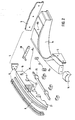
- Figure 1 shows a sheet metal part to be produced, for example, here a car side wall in the front right. It requires cutting, folding, snapping, pulling, and other operations to make it, typically cutting, snapping, pulling, and pusher tools for undercuts.
- FIGS. 1 a to 1 c The undercuts can be seen in FIGS. 1 a to 1 c, FIG. 1 a drawing a section along line AA and FIG. 1 b a section along line BB in FIG. 1 and FIG. 1 c the detail enclosed by circle X in FIG. 1 a, namely the water channel , enlarged.
- the new sheet metal forming tool consists of several parts so that the finished sheet metal part can also be lifted off the punch (see the undercuts in Figures 1a and 1b).
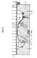
- all the tool elements required for manufacturing the sheet metal part are integrated in the stamp and sheet metal holder (FIGS. 2 and 3).
- Figure 3 shows the complete universal tool shown in section. This consists of shaping tool parts 1a, 1b and 1c, which are designed here as positive tool parts. The invention is not limited to this, however, it can be also act as negative tool parts.
- These shaping tool parts 1a, 1b, 1c are designed in such a way that they allow demolding for undercuts.
- the lateral sheet metal holder 2 which can be rigid or movable, the perforating device 3 to be described below (see FIG. 4), the demoulding mechanism 4 and the cutting strips 5 for intermediate cutting, the cutting strips 6 for final cutting, cutting strips 7 for the shaped plate can be clearly seen as well as (process-dependent) lot parts 8, which are necessary in sheet metal part production in several pressing stages.
- 9 is an insert for presenting the material in difficult areas or for changes.
- One recognizes the mechanism necessary for assembly, for lifting and for operations such as the pivot guide 20, the pivotable loose part with undercut 21, centering cams 22 which are received in a corresponding bore 23, the lifting device 24 or locking device 25, the component 1c For example, for punching and putting through (closed folding) is suitable.
- the cutting ring 3, which is only partially shown, can be clearly seen in FIG. 3. It consists of the hole, the actual cutting ring to be used, the counterholder and the disc spring to be described.
- FIG. 3 shows essentially in the right part of the figure that a number of components (apart from the hole device 3 already mentioned) are spring-loaded, such as the cutting strips 5 for intermediate trimming and the cutting strips 6 and 7.
- Stamp and sheet metal holder are thus mutually movable here .
- the corresponding parts are arranged without spring support.
- the stamp and sheet holder are rigid. You can also use one piece for simpler sheet metal parts be formed when a separate lifting mechanism 24 is not required due to the lack of undercuts.
- the stamp 1a, 1b, 1c is movable relative to the sheet metal holder 2. The movement can be brought about by mechanical, hydraulic, pneumatic or other means.
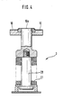
- FIG. 4 shows the punching device 3 of FIGS. 2 and 3 in detail.
- the punching process has already taken place.
- a certain presettable pressure for example 700 bar
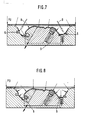
- FIGS. 5 to 9 How to work with the sheet metal forming tool or how the method according to the invention is illustrated schematically in FIGS. 5 to 9 described below.
- the start of the pressing process is shown in FIG.
- the metal sheet (blank) is cut at the points shown by arrows A.
- the material flows after (first intermediate trimming) (p1> p0).
- the pressure continues to build.
- Figure 7 shows the situation after a further increase in pressure.
- cutting strips 5 are attached, on which the sheet material is cut. See arrows B (second intermediate trim (p2> p1). The pressure is increased further.
- Figure 8 shows the molded part when pressed p3> p2).
- the cutting strips 6 are used for the final trimming, which enables the material to flow again.
- the area X is shaped as well as punching, folding, undercutting and putting through. If necessary, certain tool elements are spring loaded.
- the hole through the punching device 3 is only cut when the sheet metal has been formed.
- the stroke movement C takes place, for example, mechanically, hydraulically or pneumatically.
- the stamp elements 1a, 1b, 1c are raised, the finished part 10 ⁇ (side wall of a car, for example) is removed just like the waste pieces.
- the demolding process takes place as follows: The sheet metal part 10 ⁇ is pushed to the left. The sheet metal part is then pushed forward and finally the sheet metal part is removed upwards. If required, any number of tool elements can be flexibly designed according to the spring base 3 described above.
- the part can also be pressed in stages (in one or more tool parts, with or without loose parts).
- the intermediate cuts can be made in the press or conventionally (for example by hand, using a laser, cutting tools, etc.).
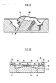
- FIG. 10 shows a special design of the tool, which is intended in particular for the production of flat components with a low degree of deformation. With such parts there is a risk that the sheet in its central region very quickly comes to rest against the punch and is held here in such a way that sufficient stretching of the component in the central region is not achieved, with the result that this region has lower strength properties.
- the sheet metal holder ring 2 in the tool according to FIG. 10 is designed so high that it extends a sufficiently large distance above the highest point of the punch 1a.
- a sheet metal holder ring 31 is provided, while the cutting strips 7 shown in FIG. 3 are omitted for the initial trimming.
- the edge of the sheet metal is firmly held between the sheet metal holder and the sheet metal holder ring, so that a sufficient extension of the central area of the sheet metal is ensured before it contacts the upper areas of the punch.
- the sheet metal holder is provided with one or more projections, for example beads (32), on its supporting surface, the corresponding depressions (33) in the sheet metal holder ring are adapted and project into this. Only when the pressure builds up further after the sheet has been sufficiently stretched in the middle region does an end or intermediate trimming take place in the drawing trench 34 shortly before the point at which the component threatens to tear.
- the tool shown in FIG. 10 can, moreover, be designed similarly to the tool in FIG. 3, that is to say with further tool parts.
Landscapes
- Engineering & Computer Science (AREA)
- Mechanical Engineering (AREA)
- Physics & Mathematics (AREA)
- Fluid Mechanics (AREA)
- Shaping Metal By Deep-Drawing, Or The Like (AREA)
- Punching Or Piercing (AREA)
Applications Claiming Priority (2)
| Application Number | Priority Date | Filing Date | Title |
|---|---|---|---|
| DE19873709181 DE3709181A1 (de) | 1987-03-20 | 1987-03-20 | Verfahren zur herstellung von komplizierten blechteilen und werkzeug fuer die druckumformung solcher blechteile |
| DE3709181 | 1987-03-20 |
Publications (2)
| Publication Number | Publication Date |
|---|---|
| EP0288705A2 true EP0288705A2 (fr) | 1988-11-02 |
| EP0288705A3 EP0288705A3 (fr) | 1990-06-27 |
Family
ID=6323587
Family Applications (1)
| Application Number | Title | Priority Date | Filing Date |
|---|---|---|---|
| EP88103937A Withdrawn EP0288705A3 (fr) | 1987-03-20 | 1988-03-12 | Procédé de fabrication de pièces compliquées en tôle et dispositif pour réaliser le procédé |
Country Status (3)
| Country | Link |
|---|---|
| EP (1) | EP0288705A3 (fr) |
| JP (1) | JPS6415230A (fr) |
| DE (1) | DE3709181A1 (fr) |
Cited By (16)
| Publication number | Priority date | Publication date | Assignee | Title |
|---|---|---|---|---|
| EP0879657A3 (fr) * | 1997-05-12 | 1998-12-02 | Dr. Meleghy Hydroforming GmbH & Co. KG | Procédé et dispositif de fabrication d'un corps creux |
| WO1999062652A1 (fr) * | 1998-06-01 | 1999-12-09 | Flow Holdings Gmbh (Sagl) Limited Liability Company | Dispositif et procede de formage d'articles plats |
| WO2003097268A1 (fr) * | 2002-05-15 | 2003-11-27 | Flow Holdings Sagl | Outil de façonnage |
| WO2004028719A1 (fr) * | 2002-09-24 | 2004-04-08 | The Boeing Company | Procedes de production de panneaux de revetement pour des structures d'avions par usinage et par formage par explosion |
| DE102004019693A1 (de) * | 2004-04-20 | 2005-11-17 | Volkswagen Ag | Verfahren und Vorrichtung zum Herstellen eines gehärteten Blechprofils |
| US7155948B2 (en) | 2002-05-15 | 2007-01-02 | Avure Technologies Ab | Forming tool |
| US8047036B2 (en) | 2005-06-03 | 2011-11-01 | Magna International Inc. | Device and method for explosion forming |
| US8250892B2 (en) | 2006-12-01 | 2012-08-28 | Cosma Engineering Europe Ag | Closure device for explosion forming |
| US8252210B2 (en) | 2006-08-11 | 2012-08-28 | Cosma Engineering Europe Ag | Method and device for explosion forming |
| US8322175B2 (en) | 2006-12-20 | 2012-12-04 | Cosma Engineering Europe Ag | Workpiece and method for explosion forming |
| RU2502574C2 (ru) * | 2012-03-27 | 2013-12-27 | Общество с ограниченной ответственностью "АКВАПАСКАЛЬ" | Способ штамповки сильфонов из трубных заготовок |
| US8650921B2 (en) | 2006-08-11 | 2014-02-18 | Cosma Engineering Europe Ag | Method and device for explosion forming |
| US8713982B2 (en) | 2008-01-31 | 2014-05-06 | Magna International Inc. | Device for explosive forming |
| US8875553B2 (en) | 2007-02-14 | 2014-11-04 | Cosma Engineering Europe Ag | Method and mould arrangement for explosion forming |
| US8939743B2 (en) | 2007-08-02 | 2015-01-27 | Cosma Engineering Europe Ag | Device for supplying a fluid for explosion forming |
| US9393606B2 (en) | 2007-05-22 | 2016-07-19 | Cosma Engineering Europe Ag | Ignition device for explosive forming |
Families Citing this family (11)
| Publication number | Priority date | Publication date | Assignee | Title |
|---|---|---|---|---|
| AT398124B (de) * | 1991-05-15 | 1994-09-26 | Vaillant Gmbh | Leiteinrichtung für eine strömungssicherung |
| DE4232913C2 (de) * | 1992-10-01 | 1995-04-27 | Daimler Benz Ag | Zweistufiges Verfahren zum hydromechanischen explosionsunterstützen Tiefziehen von Blech und Tiefziehpresse zur Durchführung des Verfahrens |
| DE4419652A1 (de) * | 1994-06-04 | 1995-12-07 | Meckenstock H W Kg | Plattenförmiges Formelement |
| DE4434799A1 (de) * | 1994-09-29 | 1996-04-04 | Smg Sueddeutsche Maschinenbau | Verfahren und Vorrichtung zum Umformen von Metallblech |
| DE19758003B4 (de) * | 1997-01-08 | 2005-12-01 | Volkswagen Ag | Widerlager aus Blech zur Anordnung an einem Träger und Verfahren zur Herstellung |
| DE19845186A1 (de) | 1998-10-01 | 2000-04-13 | Binder Technologie Ag Gams | Fluidform |
| DE19951850C1 (de) * | 1999-10-28 | 2001-01-25 | Metallwarenfabrik Reichertshof | Verfahren und Vorrichtung zur Herstellung von Formteilen |
| DE10340794B4 (de) * | 2003-09-02 | 2012-08-16 | Ise Automotive Gmbh | Folgewerkzeug zum Herstellen eines komplex geformten und mit Öffnungen in verschiedenen Ebenen versehenen Bauteils |
| DE102007050907A1 (de) | 2007-10-23 | 2009-04-30 | Benteler Automobiltechnik Gmbh | Verfahren zur Herstellung eines gehärteten Blechprofils |
| US7802457B2 (en) * | 2008-05-05 | 2010-09-28 | Ford Global Technologies, Llc | Electrohydraulic forming tool and method of forming sheet metal blank with the same |
| DE102008027876A1 (de) * | 2008-06-11 | 2009-12-17 | Oliver Bartholomé | Verfahren und Presswerkzeug zur Herstellung eines mehrfach gekrümmten Blechziehteils |
Family Cites Families (9)
| Publication number | Priority date | Publication date | Assignee | Title |
|---|---|---|---|---|
| US2133445A (en) * | 1935-12-07 | 1938-10-18 | Douglas Aircraft Co Inc | Method for cutting and forming sheet material |
| US2308998A (en) * | 1940-05-28 | 1943-01-19 | Douglas Aircraft Co Inc | Method and means for cutting and forming sheet metal |
| US2377664A (en) * | 1941-12-20 | 1945-06-05 | Armstrong Cork Co | Sheet metal shaping and shearing |
| US2490695A (en) * | 1946-09-11 | 1949-12-06 | Leutheuser Andrew | Hydraulic die |
| GB1106701A (en) * | 1963-11-04 | 1968-03-20 | Nat Res Dev | Improvements in or relating to explosion-forming processes |
| FR1433385A (fr) * | 1965-01-08 | 1966-04-01 | Procédé pour découper et emboutir simultanément au moyen d'une presse, et appareillage pour exécuter ce procédé | |
| DE2258790A1 (de) * | 1972-12-01 | 1974-06-20 | Mak Maschinenbau Gmbh | Verfahren und vorrichtung zur herstellung eines hohlkoerpers mit einer aushalsung durch explosiv-verformung |
| DE2337176C3 (de) * | 1973-07-21 | 1981-08-06 | Tokyu Sharyo Seizo K.K., Yokohama, Kanagawa | Vorrichtung zum Hochgeschwindigkeitsumformen vom metallischen rohrförmigen Werkstücken in einer mehrteiligen Formkammer |
| US4483170A (en) * | 1982-12-16 | 1984-11-20 | Toyota Jidosha Kabushiki Kaisha | Press machine structure |
-
1987
- 1987-03-20 DE DE19873709181 patent/DE3709181A1/de not_active Withdrawn
-
1988
- 1988-03-12 EP EP88103937A patent/EP0288705A3/fr not_active Withdrawn
- 1988-03-18 JP JP63065601A patent/JPS6415230A/ja active Pending
Cited By (21)
| Publication number | Priority date | Publication date | Assignee | Title |
|---|---|---|---|---|
| US6418607B1 (en) | 1997-05-12 | 2002-07-16 | Dr. Meleghy Hydroforming Gmbh & Co. Kg | Method and apparatus for fabricating a hollow body |
| EP0879657A3 (fr) * | 1997-05-12 | 1998-12-02 | Dr. Meleghy Hydroforming GmbH & Co. KG | Procédé et dispositif de fabrication d'un corps creux |
| WO1999062652A1 (fr) * | 1998-06-01 | 1999-12-09 | Flow Holdings Gmbh (Sagl) Limited Liability Company | Dispositif et procede de formage d'articles plats |
| US6178796B1 (en) | 1998-06-01 | 2001-01-30 | Flow Holdings Gmbh (Sagl) Llc | Device and method for shaping flat articles |
| CN1095705C (zh) * | 1998-06-01 | 2002-12-11 | 弗洛霍丁斯有限公司 | 从坯料高压成形扁平制品的装置和方法及该装置的用途 |
| WO2003097268A1 (fr) * | 2002-05-15 | 2003-11-27 | Flow Holdings Sagl | Outil de façonnage |
| US7155948B2 (en) | 2002-05-15 | 2007-01-02 | Avure Technologies Ab | Forming tool |
| WO2004028719A1 (fr) * | 2002-09-24 | 2004-04-08 | The Boeing Company | Procedes de production de panneaux de revetement pour des structures d'avions par usinage et par formage par explosion |
| US7093470B2 (en) | 2002-09-24 | 2006-08-22 | The Boeing Company | Methods of making integrally stiffened axial load carrying skin panels for primary aircraft structure and fuel tank structures |
| DE102004019693B4 (de) * | 2004-04-20 | 2017-10-26 | Volkswagen Ag | Verfahren zum Herstellen eines gehärteten Blechprofils |
| DE102004019693A1 (de) * | 2004-04-20 | 2005-11-17 | Volkswagen Ag | Verfahren und Vorrichtung zum Herstellen eines gehärteten Blechprofils |
| US8047036B2 (en) | 2005-06-03 | 2011-11-01 | Magna International Inc. | Device and method for explosion forming |
| US8252210B2 (en) | 2006-08-11 | 2012-08-28 | Cosma Engineering Europe Ag | Method and device for explosion forming |
| US8650921B2 (en) | 2006-08-11 | 2014-02-18 | Cosma Engineering Europe Ag | Method and device for explosion forming |
| US8250892B2 (en) | 2006-12-01 | 2012-08-28 | Cosma Engineering Europe Ag | Closure device for explosion forming |
| US8322175B2 (en) | 2006-12-20 | 2012-12-04 | Cosma Engineering Europe Ag | Workpiece and method for explosion forming |
| US8875553B2 (en) | 2007-02-14 | 2014-11-04 | Cosma Engineering Europe Ag | Method and mould arrangement for explosion forming |
| US9393606B2 (en) | 2007-05-22 | 2016-07-19 | Cosma Engineering Europe Ag | Ignition device for explosive forming |
| US8939743B2 (en) | 2007-08-02 | 2015-01-27 | Cosma Engineering Europe Ag | Device for supplying a fluid for explosion forming |
| US8713982B2 (en) | 2008-01-31 | 2014-05-06 | Magna International Inc. | Device for explosive forming |
| RU2502574C2 (ru) * | 2012-03-27 | 2013-12-27 | Общество с ограниченной ответственностью "АКВАПАСКАЛЬ" | Способ штамповки сильфонов из трубных заготовок |
Also Published As
| Publication number | Publication date |
|---|---|
| DE3709181A1 (de) | 1988-09-29 |
| JPS6415230A (en) | 1989-01-19 |
| EP0288705A3 (fr) | 1990-06-27 |
Similar Documents
| Publication | Publication Date | Title |
|---|---|---|
| EP0288705A2 (fr) | Procédé de fabrication de pièces compliquées en tôle et dispositif pour réaliser le procédé | |
| DE69001890T2 (de) | Verfahren und Vorrichtung zum Formen eines Blechzuschnittes insbesondere zur Herstellung einer Maske für eine Kathodenstrahlröhre. | |
| DE60200731T2 (de) | Platteninnenhochdruckumformung und Vorrichtung | |
| DE102007021798B4 (de) | Vorrichtung zur Herstellung von Profilen | |
| EP2701861B1 (fr) | Procédé et dispositif de fabrication de pièces embouties sans bride | |
| EP2834022B1 (fr) | Dispositif et procédé de fabrication de profilés ou d'éléments tubulaires au moins en partie fermés à partir de tôle métallique | |
| EP2259883B1 (fr) | Procédé de commande de flux de matière lors de l'emboutissage profond d'une pièce et dispositif d'emboutissage profond | |
| DE69906537T2 (de) | Vorrichtung und verfahren zum streckformen | |
| EP1117496B1 (fr) | Moule a fluide | |
| WO2007093159A2 (fr) | Outil à rouler à emboutissage intégré | |
| EP1097758B1 (fr) | Méthode de formage d' une large tôle, en particulier une partie de carrosserie d'un véhicule | |
| EP2208551B1 (fr) | Procédé de fabrication d'une pièce de tôle préformée complexe | |
| DE102007009705B3 (de) | Bearbeitungsvorrichtung sowie Verfahren zur Herstellung und Bearbeitung von Formteilen unterschiedlicher dreidimensionaler Struktur | |
| DE69109457T2 (de) | Vorrichtung zum Formstanzen von Blattmaterialen, insbesondere von Blechplättchen. | |
| DE69909485T2 (de) | Vorrichtung und verfahren zum formen von flachen gegenständen | |
| EP1029611B1 (fr) | Dispositif pour la fabrication de produits creux courbes contre-dépouillés par hydroformage | |
| EP1492635A1 (fr) | Procede et outil de matri age destines a la fabrication d'un composant a partir d'une tole de structure courbe | |
| DE10313072B4 (de) | Verfahren und Vorrichtung zum hydromechanischen Tiefziehen | |
| EP0845312B1 (fr) | Outil pour formage à haute pression utilisable avec flexibilité | |
| EP0953386A2 (fr) | Dispositif et méthode de connection des pièces par déformation plastique | |
| DE19913757A1 (de) | Verfahren zur Herstellung einer Nietverbindung | |
| DE10135561C1 (de) | Verfahren zur Herstellung von Sondermodell-Karosserieteilen | |
| DD152075A1 (de) | Verfahren und vorrichtung zur verformung von blechen,insbesondere praegesicken | |
| DE2943955A1 (de) | Bremsbacke und verfahren sowie vorrichtung zu deren herstellung | |
| DE19513444A1 (de) | Verfahren und Vorrichtung zum hydrostatischen Kaltverfahren von Blechen |
Legal Events
| Date | Code | Title | Description |
|---|---|---|---|
| PUAI | Public reference made under article 153(3) epc to a published international application that has entered the european phase |
Free format text: ORIGINAL CODE: 0009012 |
|
| AK | Designated contracting states |
Kind code of ref document: A2 Designated state(s): DE FR GB IT |
|
| PUAL | Search report despatched |
Free format text: ORIGINAL CODE: 0009013 |
|
| AK | Designated contracting states |
Kind code of ref document: A3 Designated state(s): DE FR GB IT |
|
| 17P | Request for examination filed |
Effective date: 19901207 |
|
| 17Q | First examination report despatched |
Effective date: 19910827 |
|
| STAA | Information on the status of an ep patent application or granted ep patent |
Free format text: STATUS: THE APPLICATION HAS BEEN WITHDRAWN |
|
| 18W | Application withdrawn |
Withdrawal date: 19920520 |