EP0288726A1 - System zum Umladen von Waren von einem oder auf ein Fahrzeug, bestehend aus automatischen Lade- und Entladeeinheinten - Google Patents
System zum Umladen von Waren von einem oder auf ein Fahrzeug, bestehend aus automatischen Lade- und Entladeeinheinten Download PDFInfo
- Publication number
- EP0288726A1 EP0288726A1 EP88104311A EP88104311A EP0288726A1 EP 0288726 A1 EP0288726 A1 EP 0288726A1 EP 88104311 A EP88104311 A EP 88104311A EP 88104311 A EP88104311 A EP 88104311A EP 0288726 A1 EP0288726 A1 EP 0288726A1
- Authority
- EP
- European Patent Office
- Prior art keywords
- platforms
- vehicle
- goods
- load
- mobile
- Prior art date
- Legal status (The legal status is an assumption and is not a legal conclusion. Google has not performed a legal analysis and makes no representation as to the accuracy of the status listed.)
- Granted
Links
- 238000011068 loading method Methods 0.000 title description 18
- 238000004519 manufacturing process Methods 0.000 claims description 7
- 238000013519 translation Methods 0.000 abstract description 2
- 230000014616 translation Effects 0.000 abstract 1
- 239000003981 vehicle Substances 0.000 description 21
- 230000032258 transport Effects 0.000 description 6
- 238000012546 transfer Methods 0.000 description 5
- 238000000034 method Methods 0.000 description 4
- 229910052729 chemical element Inorganic materials 0.000 description 1
- 238000011161 development Methods 0.000 description 1
- 230000000694 effects Effects 0.000 description 1
- 238000003780 insertion Methods 0.000 description 1
- 230000037431 insertion Effects 0.000 description 1
- 230000000284 resting effect Effects 0.000 description 1
- 230000002311 subsequent effect Effects 0.000 description 1
- 238000011144 upstream manufacturing Methods 0.000 description 1
Images


Classifications
-
- B—PERFORMING OPERATIONS; TRANSPORTING
- B65—CONVEYING; PACKING; STORING; HANDLING THIN OR FILAMENTARY MATERIAL
- B65G—TRANSPORT OR STORAGE DEVICES, e.g. CONVEYORS FOR LOADING OR TIPPING, SHOP CONVEYOR SYSTEMS OR PNEUMATIC TUBE CONVEYORS
- B65G63/00—Transferring or trans-shipping at storage areas, railway yards or harbours or in opening mining cuts; Marshalling yard installations
- B65G63/02—Transferring or trans-shipping at storage areas, railway yards or harbours or in opening mining cuts; Marshalling yard installations with essentially horizontal transit otherwise than by bridge
- B65G63/022—Transferring or trans-shipping at storage areas, railway yards or harbours or in opening mining cuts; Marshalling yard installations with essentially horizontal transit otherwise than by bridge for articles
Definitions
- This invention relates to a system for transferring goods from a first station, such as the factory where the goods are produced, to a second station, for example represented by normal transportation vehicles of the container, mobile box or semitrailer type or railway cars, for delivery to their destination.
- a first station such as the factory where the goods are produced
- a second station for example represented by normal transportation vehicles of the container, mobile box or semitrailer type or railway cars, for delivery to their destination.
- An object of the present invention is to create the means for developing an automated goods transportation system with particular regard to intermodality, the system being based on automation of the overall flow of goods.
- a system for transferring goods from a first station for example defined by the final point of a production line or a warehouse, to a second station represented for example by goods transportation means such as railway cars, semitrailers, containers and the like, the system being characterized in that the goods arranged on load-carrying platforms are transferred from or to a vehicle, disposed on means which enable it to undergo translational movement, by vertically mobile interface means for temporarily supporting the load-carrying platforms and comprising means for horizontally transferring the load-carrying platforms from or to the vehicle.
- the interface means and the means for translationally moving the goods transporting vehicles can also be used in an intermediate stage in the transportation of the goods to the user or to a subsequent store.
- means are provided for transferring the load-carrying platforms to the interface means and comprising for example at least one convenyor belt line or rotary roller line originating from said warehouse or production line where the goods are loaded onto said platforms.
- Said interface means comprise a floor which is vertically mobile and possibly rotatable about a central axis, the floor supporting guides for the load-carrying platforms or a conveyor belt or rotary rollers; in their two smaller-length opposite ends, said platforms comprise holes able to cooperate with a vertical pin rigid with a first horizontally rotatable arm carried by a second vertically rotatable arm carried by a block slidable on a horizontal guide along a longer side of the mobile floor of the interface means and in proximity to its outer edge, said block and elements associated therewith forming the means for horizontally transferring the load-carrying platforms from or to a vehicle.
- Said mobile floor can be raised vertically by any known devices such as mechanical arms or hydropneumatic pistons fixed to a base advantageously positioned at a lower level than that on which the transfer means for the load-carrying platforms are located, so as to enable the mobile floor when its totally lowered position to accept the platforms arranged on said means.
- any known devices such as mechanical arms or hydropneumatic pistons fixed to a base advantageously positioned at a lower level than that on which the transfer means for the load-carrying platforms are located, so as to enable the mobile floor when its totally lowered position to accept the platforms arranged on said means.
- the dimensions of the load-carrying platforms will be standardised and defined according to the vehicle, for example a railway car or an articulated truck, which is to transport goods.
- said load-carrying platforms After being emptied of their goods at destination, said load-carrying platforms are returned to the loading station situated in proximity to a warehouse or to the factory in which said goods are produced. They can be reused for subsequent transportation.
- the vehicle used for final transportation of the goods After the vehicle used for final transportation of the goods has unloaded them at destination and has returned to the loading station with the platforms empty, it is placed on means which enable it to move translationally, these means comprising at least one transfer unit moving for example along an axis perpendicular to that of the mnnas for loading the goods on the platforms.
- these means comprising at least one transfer unit moving for example along an axis perpendicular to that of the mnnas for loading the goods on the platforms.
- the empty platforms are removed and then the vehicle is moved until it is aligned with second interface means carrying platforms loaded with goods. Said platforms are then inserted into the vehicle, which is thus ready for further despatch to destination.
- the point of arrival of the goods is a warehouse or a point from which they will be further forwarded, also comprises the same type of completely automated system for unloading the goods-carrying platforms from the transportation vehicles and for loading other already emptied platforms onto them, they then returning to the loading station situated in proximity to a warehouse or to the factory in which said goods are produced. In this manner a closed-cycle goods transportation system is created which is less costly than existing systems and more rapid.
- the vehicle and load-carrying platforms are constructed for example as described and represented in another patent in the name of the present applicant.
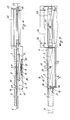
- the system shown in the form of an embodiment positioned at the exit of a prodution line or warehouse defining a first station comprises means 1 for transferring platforms 2 carrying goods 3 to interface means 4 by which the loading and unloading of said load-carrying platforms onto and from said vehicles is automated.
- the means 1 for transferring the load-carrying platforms 2 are for example one or more conveyor belts 5 connecting the interface means 4, defining a loading and/or unloading station, to a final point of a production line or warehouse.
- the interface means 4 which automate the loading and unloading comprise a mobile floor 6 which support convenyor means 7, for example in the form of roller guides, and is supported by elements able to cause it to undergo vertical translational movement (arrow F Figure 4) or rotary movement (arrows G Figure 5).
- Said elements are represented in the figures by mobile arms 8 hinged together at 9 and secured to a base 10, this base being positioned on a level 11 slightly lower than the level on which the transfer means 1 for the platforms 2 are positioned.
- the arms 8 have ends 30 slidable in tracks 31 so as to be enable the mobile floor 6 to rise.
- a control cabin 15 being provided on the opposite side to said side 12.
- An arm 16, having a forked end 17, is hinged at 18 to the block 14 and can be raised vertically (arrow W Figure 4) by rotating about said hinge 18.
- a further arm 20 is hinged at 19 to the arm 16 and supports a pin 21 which coperates with holes 22 provided in the load-carrying platforms 2 so as drag the horizontally and insert them into vehicles which are to transport the goods to their destination.
- Said vehicles are in particular railway cars 23 (as shown by way of example in the figures) or articulated trucks 24 (as shown in Figure 3) and comprise end doors 32, 33 to allow the loading and unloading of the platforms which are guided inside the vehicle and rest along their edges on pairs of guides 34 positioned at different heights, as described in a further patent of the present applicant.
- a mobile table 25 which is slidable on guides 26 and supports the vehicle (in the figures a railway car 23) in which the goods 3 are to be carried, the table 25 and guides 26 forming the vehicle translation means.
- the goods 3 are deposited on the platform 2 upstream of the system, for example at the end of a production line, not shown on the figures.
- the pin 21 is correctly positioned over the holes 22 provided at the ends of the platform. Said pin is then inserted into them by lowering the mobile arm 16.
- the platform 2 carrying the goods 3 is made to slide onto the conveyor means 7 provided on the mobile floor 7.
- the set of two connected-together platforms will obviously have an overall length equal to the length of the final means of transport into which the goods 3 are to be inserted.
- the arm 16 rigid with the block 14 slidable on the guide 13 located on the mobile floor 6 is raised so as to disengage the pin 21 from the hole 22.
- Said block 14 is then slid along the guide 13 so as to cause it to return into proximity with the end of the conveyor belt 5.
- the arm 20 supporting the pin 21 is raised (direction Z of Figure 6B) so as to position this latter over the hole 22 ⁇ in the second platform present on the mobile floor and closest to the conveyor belt 5.
- the arm 16 remains raised, and at the end of it said arm 16 is lowered so as to insert the pin 21 into the hole 22 ⁇ .
- the block 14 is again slid along the guide 13 towards the car, with the platforms carrying the goods 3 undergoing simultaneous translational movement along the mobile floor 6, so that said platforms become inserted ino the car.
- This latter operation is advantageously falicitated by the presence of guides 34 on the inner walls of the car 23.
- Unloading takes place in a like manner to that described but with the operations being carried out in the reserve order.
- the procedure is illustrated in Figure 2 or 3.
- the two lines of the system do not comprise conveyors 1 of the belt type 5, as the system is used as an intermediate station during the final transportation of the goods to the user. Again in this latter case, a line for loading the empty platforms 2 onto the cars 23 is provided.
- the table is slit on the guides 26 until the car 23 is aligned with the transfer means 1 for the platforms 2.
- the goods 3 are inserted into the car 23 which, on termination of this operation, is removed from the table and returned to the railway line. After this the table 25 returns to the position which is held during unloading.
Landscapes
- Loading Or Unloading Of Vehicles (AREA)
- Intermediate Stations On Conveyors (AREA)
- Forklifts And Lifting Vehicles (AREA)
Priority Applications (1)
| Application Number | Priority Date | Filing Date | Title |
|---|---|---|---|
| AT88104311T ATE70023T1 (de) | 1987-04-01 | 1988-03-18 | System zum umladen von waren von einem oder auf ein fahrzeug, bestehend aus automatischen ladeund entladeeinheinten. |
Applications Claiming Priority (2)
| Application Number | Priority Date | Filing Date | Title |
|---|---|---|---|
| IT19927/87A IT1203848B (it) | 1987-04-01 | 1987-04-01 | Impianto per il trasferimento di merci da o ad un veicolo presentante unita' automatizzate di carico e/o scarico |
| IT1992787 | 1987-04-01 |
Publications (2)
| Publication Number | Publication Date |
|---|---|
| EP0288726A1 true EP0288726A1 (de) | 1988-11-02 |
| EP0288726B1 EP0288726B1 (de) | 1991-12-04 |
Family
ID=11162412
Family Applications (1)
| Application Number | Title | Priority Date | Filing Date |
|---|---|---|---|
| EP88104311A Expired - Lifetime EP0288726B1 (de) | 1987-04-01 | 1988-03-18 | System zum Umladen von Waren von einem oder auf ein Fahrzeug, bestehend aus automatischen Lade- und Entladeeinheinten |
Country Status (4)
| Country | Link |
|---|---|
| EP (1) | EP0288726B1 (de) |
| AT (1) | ATE70023T1 (de) |
| DE (1) | DE3866581D1 (de) |
| IT (1) | IT1203848B (de) |
Cited By (2)
| Publication number | Priority date | Publication date | Assignee | Title |
|---|---|---|---|---|
| US5082415A (en) * | 1988-08-04 | 1992-01-21 | Takeshi Hayashi | Fork lift style loading apparatus |
| US10308449B2 (en) * | 2016-09-27 | 2019-06-04 | Cargobeamer Ag | Shuttle bar for transport of railcar pallets, freight-handling device, and freight-handling method |
Citations (3)
| Publication number | Priority date | Publication date | Assignee | Title |
|---|---|---|---|---|
| US1608213A (en) * | 1921-06-17 | 1926-11-23 | Hutchinson John Harold | Loading and unloading apparatus |
| DE2936160A1 (de) * | 1979-09-07 | 1981-04-02 | Eisenbau Wyhlen GmbH, 7889 Grenzach-Wyhlen | Anlage zum verladen schwerer lasten auf lastfahrzeuge o.dgl. mittels belademaschine |
| DE3436721C1 (de) * | 1984-10-06 | 1985-10-10 | Audi AG, 8070 Ingolstadt | Verfahren zum Verladen von Fahrzeugen auf Eisenbahnwaggons |
-
1987
- 1987-04-01 IT IT19927/87A patent/IT1203848B/it active
-
1988
- 1988-03-18 AT AT88104311T patent/ATE70023T1/de not_active IP Right Cessation
- 1988-03-18 DE DE8888104311T patent/DE3866581D1/de not_active Expired - Fee Related
- 1988-03-18 EP EP88104311A patent/EP0288726B1/de not_active Expired - Lifetime
Patent Citations (3)
| Publication number | Priority date | Publication date | Assignee | Title |
|---|---|---|---|---|
| US1608213A (en) * | 1921-06-17 | 1926-11-23 | Hutchinson John Harold | Loading and unloading apparatus |
| DE2936160A1 (de) * | 1979-09-07 | 1981-04-02 | Eisenbau Wyhlen GmbH, 7889 Grenzach-Wyhlen | Anlage zum verladen schwerer lasten auf lastfahrzeuge o.dgl. mittels belademaschine |
| DE3436721C1 (de) * | 1984-10-06 | 1985-10-10 | Audi AG, 8070 Ingolstadt | Verfahren zum Verladen von Fahrzeugen auf Eisenbahnwaggons |
Cited By (2)
| Publication number | Priority date | Publication date | Assignee | Title |
|---|---|---|---|---|
| US5082415A (en) * | 1988-08-04 | 1992-01-21 | Takeshi Hayashi | Fork lift style loading apparatus |
| US10308449B2 (en) * | 2016-09-27 | 2019-06-04 | Cargobeamer Ag | Shuttle bar for transport of railcar pallets, freight-handling device, and freight-handling method |
Also Published As
| Publication number | Publication date |
|---|---|
| EP0288726B1 (de) | 1991-12-04 |
| IT8719927A0 (it) | 1987-04-01 |
| IT1203848B (it) | 1989-02-23 |
| ATE70023T1 (de) | 1991-12-15 |
| DE3866581D1 (de) | 1992-01-16 |
Similar Documents
| Publication | Publication Date | Title |
|---|---|---|
| CN115724099B (zh) | 组合式仓储系统及其组装方法 | |
| CN114162509B (zh) | 物品处理系统与方法 | |
| CN110626692B (zh) | 可移动式密集存拣装置、组合式仓储系统及其组装方法 | |
| CN211768039U (zh) | 仓储系统 | |
| CN206348838U (zh) | 移动式物流集成处理系统 | |
| CN210504200U (zh) | 一种智能分拣系统 | |
| CN107651350A (zh) | 物流对接系统及方法、工作站 | |
| KR20180028799A (ko) | 전철 화물 배송 시스템 | |
| JPH1045257A (ja) | 貨物取り扱い装置 | |
| EP0288726A1 (de) | System zum Umladen von Waren von einem oder auf ein Fahrzeug, bestehend aus automatischen Lade- und Entladeeinheinten | |
| FI111157B (fi) | Menetelmä ja sovitelma paperi-, kartonki- ja sellurullien lastaamiseksi kuljetusvälineeseen | |
| CN110612261A (zh) | 容器更换设备 | |
| JP4082918B2 (ja) | 段積み物形成方法および段積み物形成設備 | |
| CN218809169U (zh) | 一种无人运输系统 | |
| EP0025776B1 (de) | Speicheranlage für Objekte, insbesondere für Raupenkettenglieder | |
| CN112849882B (zh) | 胚布仓储装置及其使用方法 | |
| JPH0224736B2 (de) | ||
| CN108750724B (zh) | 装车系统及方法 | |
| JP2003143714A (ja) | 電動車両のバッテリ交換装置 | |
| US5487635A (en) | Slide-in store for roller pallets and a process for inserting goods into and withdrawing goods out of said store | |
| CN111470191A (zh) | 一种物流智能货厢 | |
| CN108750726B (zh) | 装车系统及方法 | |
| CN119319988A (zh) | 滤棒盘进出库系统和滤棒盘进出库方法 | |
| JPS63263145A (ja) | 車輌荷台のパレツト荷役機構 | |
| JPH0289795A (ja) | 異質物振分け処理装置 |
Legal Events
| Date | Code | Title | Description |
|---|---|---|---|
| PUAI | Public reference made under article 153(3) epc to a published international application that has entered the european phase |
Free format text: ORIGINAL CODE: 0009012 |
|
| AK | Designated contracting states |
Kind code of ref document: A1 Designated state(s): AT BE CH DE FR GB LI NL SE |
|
| 17P | Request for examination filed |
Effective date: 19890222 |
|
| 17Q | First examination report despatched |
Effective date: 19901018 |
|
| GRAA | (expected) grant |
Free format text: ORIGINAL CODE: 0009210 |
|
| AK | Designated contracting states |
Kind code of ref document: B1 Designated state(s): AT BE CH DE FR GB LI NL SE |
|
| PG25 | Lapsed in a contracting state [announced via postgrant information from national office to epo] |
Ref country code: SE Effective date: 19911204 Ref country code: AT Effective date: 19911204 |
|
| REF | Corresponds to: |
Ref document number: 70023 Country of ref document: AT Date of ref document: 19911215 Kind code of ref document: T |
|
| REF | Corresponds to: |
Ref document number: 3866581 Country of ref document: DE Date of ref document: 19920116 |
|
| ET | Fr: translation filed | ||
| PLBE | No opposition filed within time limit |
Free format text: ORIGINAL CODE: 0009261 |
|
| STAA | Information on the status of an ep patent application or granted ep patent |
Free format text: STATUS: NO OPPOSITION FILED WITHIN TIME LIMIT |
|
| 26N | No opposition filed | ||
| REG | Reference to a national code |
Ref country code: GB Ref legal event code: IF02 |
|
| PGFP | Annual fee paid to national office [announced via postgrant information from national office to epo] |
Ref country code: BE Payment date: 20020314 Year of fee payment: 15 |
|
| PGFP | Annual fee paid to national office [announced via postgrant information from national office to epo] |
Ref country code: NL Payment date: 20020328 Year of fee payment: 15 Ref country code: FR Payment date: 20020328 Year of fee payment: 15 |
|
| PGFP | Annual fee paid to national office [announced via postgrant information from national office to epo] |
Ref country code: GB Payment date: 20020402 Year of fee payment: 15 |
|
| PGFP | Annual fee paid to national office [announced via postgrant information from national office to epo] |
Ref country code: DE Payment date: 20020514 Year of fee payment: 15 |
|
| PGFP | Annual fee paid to national office [announced via postgrant information from national office to epo] |
Ref country code: CH Payment date: 20020627 Year of fee payment: 15 |
|
| PG25 | Lapsed in a contracting state [announced via postgrant information from national office to epo] |
Ref country code: GB Free format text: LAPSE BECAUSE OF NON-PAYMENT OF DUE FEES Effective date: 20030318 |
|
| PG25 | Lapsed in a contracting state [announced via postgrant information from national office to epo] |
Ref country code: LI Free format text: LAPSE BECAUSE OF NON-PAYMENT OF DUE FEES Effective date: 20030331 Ref country code: CH Free format text: LAPSE BECAUSE OF NON-PAYMENT OF DUE FEES Effective date: 20030331 Ref country code: BE Free format text: LAPSE BECAUSE OF NON-PAYMENT OF DUE FEES Effective date: 20030331 |
|
| BERE | Be: lapsed |
Owner name: *COSTAMASNAGA S.P.A. Effective date: 20030331 |
|
| PG25 | Lapsed in a contracting state [announced via postgrant information from national office to epo] |
Ref country code: NL Free format text: LAPSE BECAUSE OF NON-PAYMENT OF DUE FEES Effective date: 20031001 Ref country code: DE Free format text: LAPSE BECAUSE OF NON-PAYMENT OF DUE FEES Effective date: 20031001 |
|
| GBPC | Gb: european patent ceased through non-payment of renewal fee |
Effective date: 20030318 |
|
| REG | Reference to a national code |
Ref country code: CH Ref legal event code: PL |
|
| PG25 | Lapsed in a contracting state [announced via postgrant information from national office to epo] |
Ref country code: FR Free format text: LAPSE BECAUSE OF NON-PAYMENT OF DUE FEES Effective date: 20031127 |
|
| NLV4 | Nl: lapsed or anulled due to non-payment of the annual fee |
Effective date: 20031001 |
|
| REG | Reference to a national code |
Ref country code: FR Ref legal event code: ST |