EP0291978A2 - Antiskid device - Google Patents
Antiskid device Download PDFInfo
- Publication number
- EP0291978A2 EP0291978A2 EP88108040A EP88108040A EP0291978A2 EP 0291978 A2 EP0291978 A2 EP 0291978A2 EP 88108040 A EP88108040 A EP 88108040A EP 88108040 A EP88108040 A EP 88108040A EP 0291978 A2 EP0291978 A2 EP 0291978A2
- Authority
- EP
- European Patent Office
- Prior art keywords
- wheels
- circuit
- signal
- command
- braking pressure
- Prior art date
- Legal status (The legal status is an assumption and is not a legal conclusion. Google has not performed a legal analysis and makes no representation as to the accuracy of the status listed.)
- Granted
Links
Images


Classifications
-
- B—PERFORMING OPERATIONS; TRANSPORTING
- B60—VEHICLES IN GENERAL
- B60T—VEHICLE BRAKE CONTROL SYSTEMS OR PARTS THEREOF; BRAKE CONTROL SYSTEMS OR PARTS THEREOF, IN GENERAL; ARRANGEMENT OF BRAKING ELEMENTS ON VEHICLES IN GENERAL; PORTABLE DEVICES FOR PREVENTING UNWANTED MOVEMENT OF VEHICLES; VEHICLE MODIFICATIONS TO FACILITATE COOLING OF BRAKES
- B60T8/00—Arrangements for adjusting wheel-braking force to meet varying vehicular or ground-surface conditions, e.g. limiting or varying distribution of braking force
- B60T8/32—Arrangements for adjusting wheel-braking force to meet varying vehicular or ground-surface conditions, e.g. limiting or varying distribution of braking force responsive to a speed condition, e.g. acceleration or deceleration
- B60T8/86—Arrangements for adjusting wheel-braking force to meet varying vehicular or ground-surface conditions, e.g. limiting or varying distribution of braking force responsive to a speed condition, e.g. acceleration or deceleration wherein the brakes are automatically applied in accordance with a speed condition and having means for overriding the automatic braking device when a skid condition occurs
-
- B—PERFORMING OPERATIONS; TRANSPORTING
- B60—VEHICLES IN GENERAL
- B60T—VEHICLE BRAKE CONTROL SYSTEMS OR PARTS THEREOF; BRAKE CONTROL SYSTEMS OR PARTS THEREOF, IN GENERAL; ARRANGEMENT OF BRAKING ELEMENTS ON VEHICLES IN GENERAL; PORTABLE DEVICES FOR PREVENTING UNWANTED MOVEMENT OF VEHICLES; VEHICLE MODIFICATIONS TO FACILITATE COOLING OF BRAKES
- B60T8/00—Arrangements for adjusting wheel-braking force to meet varying vehicular or ground-surface conditions, e.g. limiting or varying distribution of braking force
- B60T8/17—Using electrical or electronic regulation means to control braking
- B60T8/176—Brake regulation specially adapted to prevent excessive wheel slip during vehicle deceleration, e.g. ABS
- B60T8/1761—Brake regulation specially adapted to prevent excessive wheel slip during vehicle deceleration, e.g. ABS responsive to wheel or brake dynamics, e.g. wheel slip, wheel acceleration or rate of change of brake fluid pressure
- B60T8/17616—Microprocessor-based systems
-
- Y—GENERAL TAGGING OF NEW TECHNOLOGICAL DEVELOPMENTS; GENERAL TAGGING OF CROSS-SECTIONAL TECHNOLOGIES SPANNING OVER SEVERAL SECTIONS OF THE IPC; TECHNICAL SUBJECTS COVERED BY FORMER USPC CROSS-REFERENCE ART COLLECTIONS [XRACs] AND DIGESTS
- Y10—TECHNICAL SUBJECTS COVERED BY FORMER USPC
- Y10S—TECHNICAL SUBJECTS COVERED BY FORMER USPC CROSS-REFERENCE ART COLLECTIONS [XRACs] AND DIGESTS
- Y10S303/00—Fluid-pressure and analogous brake systems
- Y10S303/05—Acceleration peak detection
Definitions
- the present invention generally relates to a motor vehicle and more particularly, to an antiskid device for utilizing a braking force efficiently through detection of a locking state of wheels of the motor vehicle.
- an antiskid device is arranged as shown in Fig. 1.
- an AC voltage supplied from a wheel speed sensor R is converted into pulses by an interface circuit 22.
- the pulses are counted by a pulse processing circuit 23 so as to be inputted, as a wheel speed signal, to a circuit 24 for performing arithmetic operation and detecting a locking state of wheels of a motor vehicle.
- a circuit 24 for performing arithmetic operation of an estimated vehicle speed, a deceleration or an acceleration is performed on the basis of the wheel speed signal.
- the circuit 24 detects that the wheels are in a state towards locking through comparison between the arithmetic results and various threshold values, the circuit 24 gives a command of reducing a braking pressure.
- the circuit 24 issues a command of increasing the braking pressure. Furthermore, under a certain condition, the circuit 24 gives a command of maintaining the braking pressure even during issuance of the command of increasing or decreasing the braking pressure.
- a solenoid driving circuit 25 energizes solenoids SOL1 and SOL2.
- pressure control valves V1 and V2 are displaced in the rightward direction in Fig. 1. Therefore, the pressure control valve V1 shuts off a brake fluid pressure circuit from a brake fluid pressure generator composed of a master cylinder 26 and an accumulator 29 and the pressure control valve V2 establishes communication of a brake fluid pressure circuit from a wheel cylinder 27 to a reservoir 28, while brake fluid discharged to the reservoir 28 by a pump 30 is returned to the accumulator 29 and the master cylinder 26. As a result, the braking pressure is decreased.
- the solenoid driving circuit 25 de-energizes the solenoids SOL1 and SOL2, so that the pressure control valves V1 and V2 are returned to the positions shown in Fig. 1 and thus, the wheel cylinder 27 is communicated with the brake fluid pressure generator composed of the master cylinder 26 and the accumulator 29.
- the solenoid driving circuit 25 energizes the solenoid SOL1 and de-energizes the solenoid SOL2.
- the pressure control valve V1 is displaced in the rightward direction in Fig. 1, while the pressure control valve V2 is held in the position shown in Fig. 1. Therefore, the wheel cylinder 27 is isolated from the brake fluid pressure generator, so that the pressure of the wheel cylinder 27 is contained in the circuit of the wheel cylinder 27 and thus, the braking pressure is maintained at a constant value.
- a control means is provided in the antiskid device referred to above as disclosed, for example, in Japanese Patent Publication (examined) No. 30588/1984.
- the control means gives, for a second preset time period after lapse of the first preset time period, the command of maintaining the braking pressure by suspending the command of decreasing the braking pressure.
- This action of the control means is performed for the following purpose. Namely, progress of decrease of the braking pressure is detected once in the course of decrease of the braking pressure and then, the braking pressure is further decreased if necessary such that a braking distance is shortened without decreasing the braking pressure excessively.
- an essential object of the present invention is, with a view to solving the above described problems, to provide an antiskid device which eliminates risks of excessive reduction of a braking pressure and maintenance of the braking pressure in a too early stage by properly changing, in response to behaviors of wheels, a point of time of starting maintaining the braking pressure during reduction of the braking pressure and a time period for maintaining the braking pressure during reduction of the braking pressure.
- an antiskid device of the present invention after a command of decreasing a braking pressure has been issued upon detection of a wheel state towards locking, a peak of a deceleration of the wheels is detected.
- a command of maintaining the braking pressure is issued while the deceleration of the wheels exceeds a reference value for change of the deceleration, with the reference value being a linear function having the predetermined value as an initial value.
- the deceleration represents rate of change of the wheel speed.
- the deceleration has reached the peak, it is anticipated that the wheel speed substantially changes to a state towards recovery. Therefore, when the deceleration has exceeded the predetermined value from the peak, it can be decided that the wheel speed is positively changing to the state towards recovery.
- the deceleration is compared with the linear function so as to determine whether or not the wheel speed changes to the state towards recovery normally.
- the command of maintaining the braking pressure is issued so as to suspend reduction of the braking pressure such that a waiting state is brought about.
- the antiskid device includes a sensor R, an interface circuit 22, a pulse processing circuit 23, a circuit 24 for performing arithmetic operation and detecting a locking state of wheels of a motor vehicle, a solenoid driving circuit 25, a master cylinder 26, a wheel cylinder 27, a reservoir 28, an accumulator 29, a pump 30, solenoids SOL1 and SOL2 and pressure control valves V1 and V2.
- a wheel speed detecting means 1 is constituted by the sensor R, the interface circuit 22 and the pulse processing circuit 23.
- the circuit 24 includes a wheel speed calculating circuit 2, a calculation circuit 3 for calculating an estimated vehicle speed Vv, a signal calculating circuit 4 for evaluating a slip speed of the wheels, a circuit 5, evaluation circuits 6 and 7, a differentiation circuit 8, a deceleration evaluating circuit 9 and a detection circuit 11 for detecting a peak of a deceleration of the wheels.
- the circuit 24 includes a flip-flop 12, an inverter 13, AND gates 14 and 15, an OR gate 16, calculation circuits 17 and 18, a circuit 19 and AND gates 20 and 21.
- a pulse signal proportional to a rotational speed of the wheels is supplied from the wheel speed detecting means 1 to the wheel speed calculating circuit 2 which counts the number of pulses so as to output a wheel speed signal Vw.
- the calculation circuit 3 receives the signal Vw so as to calculate the estimated vehicle speed Vv. Meanwhile, in response to the wheel speed signal Vw and the vehicle speed signal Vv, the signal calculating circuit 4 calculates a signal S for evaluating the slip speed of the wheels.
- the above described signal ⁇ is applied to the evaluation circuits 6 and 7 which evaluate the signal ⁇ by a threshold value ⁇ 1 for start of slip and a threshold value ⁇ 2 for recovery of slip so as to output ON or OFF logical signals O2 and O3, respectively.
- the wheel speed signal Vw is applied to the differentiation circuit 8 which calculates the deceleration of the wheels so as to obtain a deceleration signalV ⁇ w.
- the deceleration signalV ⁇ w is supplied to the deceleration evaluating circuit 9 so as to be evaluated by a deceleration threshold value of (-b) such that a result of the evaluation is outputted, as a logical signal O1, from the deceleration evaluating circuit 9. Meanwhile, the deceleration signalV ⁇ w is applied to the detection circuit 11.
- the detection circuit 11 outputs a signal O4 to the flip-flop 12 so as to set the flip-flop 12.
- the circuit 11 and the flip-flop 12 are reset by a signal into which a signal O8 indicative of continuation of slip is inverted by the inverter 13 as will be described later.
- the circuit 3 When the wheel speed signal Vw starts decreasing upon actuation of the brake, the circuit 3 generates the predetermined estimated vehicle speed signal Vv. In response to the signals Vv and Vw, the circuit 4 calculates the signal S for evaluating the slip speed and the circuit 5 calculates the slip speed signal ⁇ .
- the circuit 6 turns on the signal O2. Further additionallymore, the deceleration signalV ⁇ w which is obtained by differentiating the wheel speed signal Vw is evaluated by the circuit 9. When the deceleration signalV ⁇ w is smaller than the predetermined value of (-b), the circuit 9 turns on the signal O1. Meanwhile, since the peak of the deceleration does not yet appear, the signal O4 is turned off and thus, the signal O5 is also held in the OFF state. Therefore, the output signal O6 of the AND gate 14 is turned on.
- the peak detection signal O4 is turned on so as to actuate the flip-flop 12 such that the signal O5 is turned on, so that the output signal O6 of the AND gate 14 is turned off.
- the output signal O5 of the flip-flop 12 is inputted to the AND gate 15, while the output terminal of the circuit 7 is connected to a NOT terminal of the AND gate 15.
- the signal O5 of the flip-flop 12 is in the ON state.
- the slip speed signal ⁇ is not lower than the threshold value ⁇ 2 for recovery of slip, the output signal O3 of the evaluation circuit 7 is in the OFF state. Therefore, the output signal O7 of the AND gate 15 is turned on.
- the output signals O6 and O7 of the AND gates 14 and 15 are inputted to the OR gate 16.
- the output signal of the OR gate 16 i.e. the signal O8 indicative of continuation of slip is turned on.
- the signal O8 is turned off when the signal O7 has been turned off upon turning on of the output signal O3 of the evaluation circuit 7, namely when the slip speed signal ⁇ has become smaller than the threshold value ⁇ 2 for recovery of slip.
- the detection circuit 11 not only outputs the peak detection signal O4 as described above but latches the peak Dpeak so as to output the peak Dpeak to the circuit 17.
- the circuit 17 subtracts a predetermined evaluation value of (+d) from the peak Dpeak and outputs the result Dwd of subtraction to the calculation circuit 18.
- a deceleration change reference value Dl is calculated by setting the value Dwd as an initial value.
- the deceleration change reference value Dl is obtained by changing the value Dwd with an arbitrarily selected predetermined reduction ration ⁇ o .
- the circuit 19 evaluates the decelerationV ⁇ w by using the reference value Dl as an evaluation reference, i.e. a threshold value so as to output the result of evaluation to the AND gate 21 by a logical signal O9.
- the signal O9 of the circuit 19 is turned on, so that the output signal O11 of the AND gate 21 is turned on and thus, the braking pressure is maintained at a constant value. Since the signal O11 is applied to a NOT terminal of the AND gate 20, the signal O10 is held in the OFF state while the signal O11 is in the ON state even if the signal O8 is in the ON state.
- the threshold values of (-b) and ⁇ 1 are, respectively, provided for the deceleration and the slip speed as conditions for turning on the signal O6 such that the signal O6 is turned on only when the deceleration and the slip speed satisfy the threshold values of (-b) and ⁇ 1, respectively at the same time.
- the signal O6 is turned on under another condition.
- the signal O6 may be turned on when either one of the deceleration and the slip speed satisfies the corresponding threshold value.
- circuit described in the above embodiment can be formed by hardware.
- functions identical with those of the circuit can be obtained by software incorporated into a microcomputer.
- the peak of the decleration is detected during reduction of deceleration and then, the minimum recovery, i.e. (+d) from the peak of the deceleration is detected. Subsequently, a decision is made by the linear function Dl as to whether or not recovery of the deceleration from the peak progresses normally. Thus, only if the deceleration exceeds the linear function, the command of maintaining the braking pressure is issued.
Landscapes
- Engineering & Computer Science (AREA)
- Transportation (AREA)
- Mechanical Engineering (AREA)
- Microelectronics & Electronic Packaging (AREA)
- Physics & Mathematics (AREA)
- Fluid Mechanics (AREA)
- Regulating Braking Force (AREA)
Abstract
Description
- The present invention generally relates to a motor vehicle and more particularly, to an antiskid device for utilizing a braking force efficiently through detection of a locking state of wheels of the motor vehicle.
- Generally, an antiskid device is arranged as shown in Fig. 1. Initially, an AC voltage supplied from a wheel speed sensor R is converted into pulses by an
interface circuit 22. The pulses are counted by apulse processing circuit 23 so as to be inputted, as a wheel speed signal, to acircuit 24 for performing arithmetic operation and detecting a locking state of wheels of a motor vehicle. In thiscircuit 24, arithmetic operation of an estimated vehicle speed, a deceleration or an acceleration is performed on the basis of the wheel speed signal. When thecircuit 24 detects that the wheels are in a state towards locking through comparison between the arithmetic results and various threshold values, thecircuit 24 gives a command of reducing a braking pressure. Meanwhile, when the wheels are in a state towards recovery from locking, thecircuit 24 issues a command of increasing the braking pressure. Furthermore, under a certain condition, thecircuit 24 gives a command of maintaining the braking pressure even during issuance of the command of increasing or decreasing the braking pressure. - In the case where the command of decreasing the braking pressure has been given from the
circuit 24, asolenoid driving circuit 25 energizes solenoids SOL1 and SOL2. Thus, pressure control valves V1 and V2 are displaced in the rightward direction in Fig. 1. Therefore, the pressure control valve V1 shuts off a brake fluid pressure circuit from a brake fluid pressure generator composed of amaster cylinder 26 and anaccumulator 29 and the pressure control valve V2 establishes communication of a brake fluid pressure circuit from awheel cylinder 27 to areservoir 28, while brake fluid discharged to thereservoir 28 by apump 30 is returned to theaccumulator 29 and themaster cylinder 26. As a result, the braking pressure is decreased. - On the other hand, in the case where the command of increasing the braking pressure has been issued from the
circuit 24, thesolenoid driving circuit 25 de-energizes the solenoids SOL1 and SOL2, so that the pressure control valves V1 and V2 are returned to the positions shown in Fig. 1 and thus, thewheel cylinder 27 is communicated with the brake fluid pressure generator composed of themaster cylinder 26 and theaccumulator 29. - Meanwhile, when the command of maintaining the braking pressure has been given from the
circuit 24, thesolenoid driving circuit 25 energizes the solenoid SOL1 and de-energizes the solenoid SOL2. Thus, the pressure control valve V1 is displaced in the rightward direction in Fig. 1, while the pressure control valve V2 is held in the position shown in Fig. 1. Therefore, thewheel cylinder 27 is isolated from the brake fluid pressure generator, so that the pressure of thewheel cylinder 27 is contained in the circuit of thewheel cylinder 27 and thus, the braking pressure is maintained at a constant value. - A control means is provided in the antiskid device referred to above as disclosed, for example, in Japanese Patent Publication (examined) No. 30588/1984. In this prior art antiskid device, when the command of decreasing the braking pressure has been issued continuously for a first preset time period or more upon detection of the wheel state towards locking, the control means gives, for a second preset time period after lapse of the first preset time period, the command of maintaining the braking pressure by suspending the command of decreasing the braking pressure. This action of the control means is performed for the following purpose. Namely, progress of decrease of the braking pressure is detected once in the course of decrease of the braking pressure and then, the braking pressure is further decreased if necessary such that a braking distance is shortened without decreasing the braking pressure excessively.
- However, in the prior art antiskid device, if the braking pressure is maintained regardless of behaviors of the wheels upon lapse of the predetermined time period after start of decrease of the braking pressure as described above, such an undesirable phenomenon may take place that although the braking pressure is actually required to be decreased further, the wheels are locked exceedingly through maintenance of the braking pressure in a too early stage or conversely that in the case of the wheels which could have been recovered from locking even if the braking pressure had been maintained in an earlier stage, the braking pressure is decreased excessively since the braking pressure is maintained upon lapse of the predetermined time period.
- Accordingly, an essential object of the present invention is, with a view to solving the above described problems, to provide an antiskid device which eliminates risks of excessive reduction of a braking pressure and maintenance of the braking pressure in a too early stage by properly changing, in response to behaviors of wheels, a point of time of starting maintaining the braking pressure during reduction of the braking pressure and a time period for maintaining the braking pressure during reduction of the braking pressure.
- In order to accomplish this object of the present invention, in an antiskid device of the present invention, after a command of decreasing a braking pressure has been issued upon detection of a wheel state towards locking, a peak of a deceleration of the wheels is detected. Thus, when the deceleration of the wheels has exceeded a predetermined value from the peak, a command of maintaining the braking pressure is issued while the deceleration of the wheels exceeds a reference value for change of the deceleration, with the reference value being a linear function having the predetermined value as an initial value.
- Among behaviors of the wheels, the deceleration represents rate of change of the wheel speed. Thus, when the deceleration has reached the peak, it is anticipated that the wheel speed substantially changes to a state towards recovery. Therefore, when the deceleration has exceeded the predetermined value from the peak, it can be decided that the wheel speed is positively changing to the state towards recovery. Subsequently, by setting a linear function having the predetermined value as an initial value and a proper gradient, the deceleration is compared with the linear function so as to determine whether or not the wheel speed changes to the state towards recovery normally. When not only the wheel speed has changed to the state towards recovery normally but the deceleration has exceeded the linear function, the command of maintaining the braking pressure is issued so as to suspend reduction of the braking pressure such that a waiting state is brought about.
- This object and features of the present invention will become apparent from the following description taken in conjunction with the preferred embodiment thereof with reference to the accompanying drawings, in which:
- Fig. 1 is a schematic block diagram of an antiskid device according to one embodiment of the present invention;
- Fig. 2 is an electrical circuit diagram of the antiskid device of Fig. 1; and
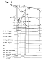
- Fig. 3 is a timing chart of signals of the antiskid device of Fig. 1.
- Before the description of the present invention proceeds, it is to be noted that like parts are designated by like reference numerals throughout several views of the accompanying drawings.
- Referring now to the drawings, there is shown in Figs. 1 to 3, an antiskid device according to one embodiment of the present invention. As shown in Fig. 1, the antiskid device includes a sensor R, an
interface circuit 22, apulse processing circuit 23, acircuit 24 for performing arithmetic operation and detecting a locking state of wheels of a motor vehicle, asolenoid driving circuit 25, amaster cylinder 26, awheel cylinder 27, areservoir 28, anaccumulator 29, apump 30, solenoids SOL1 and SOL2 and pressure control valves V1 and V2. As shown in Fig. 2, a wheel speed detecting means 1 is constituted by the sensor R, theinterface circuit 22 and thepulse processing circuit 23. - Since the present invention is characterized by the
circuit 24, thecircuit 24 is specifically described with reference to Figs. 2 and 3, hereinbelow. Thecircuit 24 includes a wheelspeed calculating circuit 2, acalculation circuit 3 for calculating an estimated vehicle speed Vv, asignal calculating circuit 4 for evaluating a slip speed of the wheels, a circuit 5,evaluation circuits differentiation circuit 8, adeceleration evaluating circuit 9 and a detection circuit 11 for detecting a peak of a deceleration of the wheels. - Furthermore, the
circuit 24 includes a flip-flop 12, aninverter 13, ANDgates OR gate 16,calculation circuits circuit 19 andAND gates speed calculating circuit 2 which counts the number of pulses so as to output a wheel speed signal Vw. Thecalculation circuit 3 receives the signal Vw so as to calculate the estimated vehicle speed Vv. Meanwhile, in response to the wheel speed signal Vw and the vehicle speed signal Vv, thesignal calculating circuit 4 calculates a signal S for evaluating the slip speed of the wheels. The circuit 5 receives these signals Vw, Vv and S so as to calculate and output a slip speed signal λ (= Vv-S-Vw). Meanwhile, the signal S is obtained by filtering an actual slip speed of (Vv-Vw) but may not be used. - The above described signal λ is applied to the
evaluation circuits - The wheel speed signal Vw is applied to the
differentiation circuit 8 which calculates the deceleration of the wheels so as to obtain a deceleration signalV̇w. The deceleration signalV̇w is supplied to thedeceleration evaluating circuit 9 so as to be evaluated by a deceleration threshold value of (-b) such that a result of the evaluation is outputted, as a logical signal O1, from thedeceleration evaluating circuit 9. Meanwhile, the deceleration signalV̇w is applied to the detection circuit 11. Thus, when the detection circuit 11 has detected the peak of the deceleration, the detection circuit 11 outputs a signal O4 to the flip-flop 12 so as to set the flip-flop 12. Meanwhile, the circuit 11 and the flip-flop 12 are reset by a signal into which a signal O8 indicative of continuation of slip is inverted by theinverter 13 as will be described later. - Hereinbelow, operation of the antiskid device during deceleration is described. When the wheel speed signal Vw starts decreasing upon actuation of the brake, the
circuit 3 generates the predetermined estimated vehicle speed signal Vv. In response to the signals Vv and Vw, thecircuit 4 calculates the signal S for evaluating the slip speed and the circuit 5 calculates the slip speed signal λ. - When this signal λ has exceeded the predetermined value λ1, the
circuit 6 turns on the signal O2. Furthermore, the deceleration signalV̇w which is obtained by differentiating the wheel speed signal Vw is evaluated by thecircuit 9. When the deceleration signalV̇w is smaller than the predetermined value of (-b), thecircuit 9 turns on the signal O1. Meanwhile, since the peak of the deceleration does not yet appear, the signal O4 is turned off and thus, the signal O5 is also held in the OFF state. Therefore, the output signal O6 of theAND gate 14 is turned on. However, when the peak Dpeak of the deceleration has been detected by the detection circuit 11, the peak detection signal O4 is turned on so as to actuate the flip-flop 12 such that the signal O5 is turned on, so that the output signal O6 of theAND gate 14 is turned off. The output signal O5 of the flip-flop 12 is inputted to theAND gate 15, while the output terminal of thecircuit 7 is connected to a NOT terminal of theAND gate 15. At this time, since the signal O5 of the flip-flop 12 is in the ON state. Meanwhile, since the slip speed signal λ is not lower than the threshold value λ2 for recovery of slip, the output signal O3 of theevaluation circuit 7 is in the OFF state. Therefore, the output signal O7 of the ANDgate 15 is turned on. - The output signals O6 and O7 of the AND
gates OR gate 16. Thus, when the signal O6 is in the ON state and the signal O7 is in the OFF state, the output signal of theOR gate 16, i.e. the signal O8 indicative of continuation of slip is turned on. Thereafter, the signal O8 is turned off when the signal O7 has been turned off upon turning on of the output signal O3 of theevaluation circuit 7, namely when the slip speed signal λ has become smaller than the threshold value λ2 for recovery of slip. - Subsequently, the detection circuit 11 not only outputs the peak detection signal O4 as described above but latches the peak Dpeak so as to output the peak Dpeak to the
circuit 17. Thecircuit 17 subtracts a predetermined evaluation value of (+d) from the peak Dpeak and outputs the result Dwd of subtraction to thecalculation circuit 18. In thecalculation circuit 18, a deceleration change reference value Dℓ is calculated by setting the value Dwd as an initial value. The deceleration change reference value Dℓ is obtained by changing the value Dwd with an arbitrarily selected predetermined reduction ration γo. Thus, assuming that character t denotes time, the deceleration change reference value Dℓ is expressed as follows.
Dℓ = Dwd+ γot - Then, the
circuit 19 evaluates the decelerationV̇w by using the reference value Dℓ as an evaluation reference, i.e. a threshold value so as to output the result of evaluation to the ANDgate 21 by a logical signal O9. - If the signal O9 of (V̇w -Dℓ) is in the OFF state, namely the decelerationV̇w is smaller than the reference value Dℓ when th signal O8 indicative of continuation of slip is in the ON state, an output signal O11 of the AND
gate 21 is turned off, so that an output signal O10 of the ANDgate 20 is turned on and thus, reduction of the braking pressure is continued. - When the decelerationV̇w has become larger than the reference value Dℓ, the signal O9 of the
circuit 19 is turned on, so that the output signal O11 of the ANDgate 21 is turned on and thus, the braking pressure is maintained at a constant value. Since the signal O11 is applied to a NOT terminal of the ANDgate 20, the signal O10 is held in the OFF state while the signal O11 is in the ON state even if the signal O8 is in the ON state. - Meanwhile, when the signal O8 indicative of continuation of slip is turned off, both of the signals O10 and O11 are turned off. Although not specifically shown, this state represents a mode for increasing the braking pressure. Meanwhile, calculation of the value Dwd and the function Dℓ in the
circuits inverter 13. - Meanwhile, in this embodiment, the threshold values of (-b) and λ1 are, respectively, provided for the deceleration and the slip speed as conditions for turning on the signal O6 such that the signal O6 is turned on only when the deceleration and the slip speed satisfy the threshold values of (-b) and λ1, respectively at the same time. However, it can also be so arranged that the signal O6 is turned on under another condition. For example, the signal O6 may be turned on when either one of the deceleration and the slip speed satisfies the corresponding threshold value.
- Furthermore, the circuit described in the above embodiment can be formed by hardware. In addition, functions identical with those of the circuit can be obtained by software incorporated into a microcomputer.
- As is clear from the foregoing description, in the antiskid device of the present invention, the peak of the decleration is detected during reduction of deceleration and then, the minimum recovery, i.e. (+d) from the peak of the deceleration is detected. Subsequently, a decision is made by the linear function Dℓ as to whether or not recovery of the deceleration from the peak progresses normally. Thus, only if the deceleration exceeds the linear function, the command of maintaining the braking pressure is issued.
- Accordingly, in accordance with the present invention, such an undesirable phenomenon does not take place that the wheels are locked excessively through maintenance of the braking pressure in a too early stage or conversely that in the case of the wheels which could have been recovered from locking even if the braking pressure had been maintained in an earlier stage, the braking pressure is decreased exceedingly, whereby the wheels can be safely recovered from locking.
- Although the present invention has been fully described by way of example with reference to the accompanying drawings, it is to be noted here that various changes and modifications will be apparent to those skilled in the art. Therefore, unless otherwise such changes and modifications depart from the scope of the present invention, they should be construed as being included therein.
Claims (2)
a wheel speed detecting means (1) for detecting speed of wheels of a motor vehicle;
an arithmetic and detection means (24) which performs arithmetic operation on the basis of a wheel speed signal supplied from said wheel speed detecting means (1);
said arithmetic and detection means (24), when having detected that the wheels are in a state towards locking, issuing a first command of decreasing a braking pressure on the wheels and, when having detected that the wheels are in a state towards recovery from locking, issuing a second command of increasing the braking pressure;
said arithmetic and detection means (24) issuing as necessary a third command of maintaining the braking pressure;
a pressure control valve means (V1, V2) which is provided for a brake fluid pressure circuit; and
an actuator means (25, SOL1, SOL2) for opening and closing said pressure control valve means (V1, V2) on the basis of the first, second and third commands;
said arithmetic and detection means (24) including a control means (2-9_, 11-21);
said control means (2-9, 11-21), after issuance of the first command, detecting a peak (Dpeak) of a deceleration (V̇w) of the wheels;
said control means (2-9, 11-21), when the deceleration (V̇w) has exceeded a predetermined value (Dwd) from the peak (Dpeak), issuing the third command while the deceleration (V̇w) exceeds a reference value (Dℓ) for change of the deceleration (V̇w), with the reference value (Dℓ) being a linear function having the predetermined value (Dwd) as an initial value.
Applications Claiming Priority (2)
| Application Number | Priority Date | Filing Date | Title |
|---|---|---|---|
| JP126324/87 | 1987-05-20 | ||
| JP62126324A JPH0729600B2 (en) | 1987-05-20 | 1987-05-20 | Anti-lock device |
Publications (3)
| Publication Number | Publication Date |
|---|---|
| EP0291978A2 true EP0291978A2 (en) | 1988-11-23 |
| EP0291978A3 EP0291978A3 (en) | 1989-12-27 |
| EP0291978B1 EP0291978B1 (en) | 1991-11-27 |
Family
ID=14932367
Family Applications (1)
| Application Number | Title | Priority Date | Filing Date |
|---|---|---|---|
| EP88108040A Expired - Lifetime EP0291978B1 (en) | 1987-05-20 | 1988-05-19 | Antiskid device |
Country Status (5)
| Country | Link |
|---|---|
| US (1) | US4901239A (en) |
| EP (1) | EP0291978B1 (en) |
| JP (1) | JPH0729600B2 (en) |
| KR (1) | KR910004603B1 (en) |
| DE (1) | DE3866426D1 (en) |
Cited By (1)
| Publication number | Priority date | Publication date | Assignee | Title |
|---|---|---|---|---|
| WO2021008750A1 (en) * | 2019-07-12 | 2021-01-21 | Robert Bosch Gmbh | Method for operating an anti-lock braking system on a vehicle and corresponding anti-lock braking system |
Families Citing this family (3)
| Publication number | Priority date | Publication date | Assignee | Title |
|---|---|---|---|---|
| DE3841977C2 (en) * | 1988-12-14 | 1997-07-10 | Bosch Gmbh Robert | Anti-lock control system |
| JP2774132B2 (en) * | 1989-03-10 | 1998-07-09 | マツダ株式会社 | Automotive slip control device |
| US5147115A (en) * | 1990-04-16 | 1992-09-15 | General Motors Corporation | Adaptive release apply algorithm |
Family Cites Families (14)
| Publication number | Priority date | Publication date | Assignee | Title |
|---|---|---|---|---|
| JPS6030582B2 (en) * | 1974-06-28 | 1985-07-17 | 株式会社デンソー | Vehicle skid control device |
| DE2930433A1 (en) * | 1979-07-26 | 1981-05-21 | Knorr-Bremse GmbH, 8000 München | BLOCKED PROTECTIVE BRAKE CONTROL CIRCUIT FOR RAIL VEHICLES |
| US4395761A (en) * | 1980-05-15 | 1983-07-26 | Honda Giken Kogyo Kabushiki Kaisha | Antiskid brake controlling method and apparatus for vehicles |
| DE3119144C2 (en) * | 1981-05-14 | 1985-01-17 | FAG Kugelfischer Georg Schäfer KGaA, 8720 Schweinfurt | Anti-lock hydraulic vehicle braking system |
| JPS59196464A (en) * | 1983-04-23 | 1984-11-07 | Nissan Motor Co Ltd | Detection of wheel speed and/or wheel acceleration/deceleration |
| JPS59209943A (en) * | 1983-05-16 | 1984-11-28 | Nissan Motor Co Ltd | Anti-skid control device |
| JPS59209942A (en) * | 1983-05-16 | 1984-11-28 | Nissan Motor Co Ltd | Anti-skid control device |
| JPS60128054A (en) * | 1983-12-13 | 1985-07-08 | Nissan Motor Co Ltd | Anti-skid control device |
| DE3435870A1 (en) * | 1984-09-29 | 1986-04-10 | Robert Bosch Gmbh, 7000 Stuttgart | ANTI-BLOCKING CONTROL SYSTEM |
| US4790607A (en) * | 1985-02-19 | 1988-12-13 | Kelsey Hayes Company | Vehicle anti-lock brake system |
| DE3535110C2 (en) * | 1985-10-02 | 1993-11-04 | Teves Gmbh Alfred | CIRCUIT ARRANGEMENT FOR CONTROLLING THE BRAKE PRESSURE OF A SLIP-CONTROLLED BRAKE SYSTEM FOR ALL-WHEEL DRIVE MOTOR VEHICLES |
| JPH0725297B2 (en) * | 1985-12-27 | 1995-03-22 | 曙ブレーキ工業株式会社 | Anti-skidding control method |
| US4761741A (en) * | 1986-07-07 | 1988-08-02 | General Motors Corporation | Anti-lock brake control system |
| US4750124A (en) * | 1986-11-19 | 1988-06-07 | General Motors Corporation | Anti-lock brake control system |
-
1987
- 1987-05-20 JP JP62126324A patent/JPH0729600B2/en not_active Expired - Fee Related
-
1988
- 1988-05-12 US US07/193,055 patent/US4901239A/en not_active Expired - Fee Related
- 1988-05-18 KR KR1019880005824A patent/KR910004603B1/en not_active Expired
- 1988-05-19 EP EP88108040A patent/EP0291978B1/en not_active Expired - Lifetime
- 1988-05-19 DE DE8888108040T patent/DE3866426D1/en not_active Expired - Lifetime
Cited By (4)
| Publication number | Priority date | Publication date | Assignee | Title |
|---|---|---|---|---|
| WO2021008750A1 (en) * | 2019-07-12 | 2021-01-21 | Robert Bosch Gmbh | Method for operating an anti-lock braking system on a vehicle and corresponding anti-lock braking system |
| CN114040868A (en) * | 2019-07-12 | 2022-02-11 | 罗伯特·博世有限公司 | Method for operating an anti-lock brake system of a vehicle and corresponding anti-lock brake system |
| CN114040868B (en) * | 2019-07-12 | 2024-04-30 | 罗伯特·博世有限公司 | Method for operating an anti-lock braking system of a vehicle and corresponding anti-lock braking system |
| US12084029B2 (en) | 2019-07-12 | 2024-09-10 | Robert Bosch Gmbh | Method for operating an antilock brake system of a vehicle and corresponding antilock brake system |
Also Published As
| Publication number | Publication date |
|---|---|
| DE3866426D1 (en) | 1992-01-09 |
| KR880013752A (en) | 1988-12-21 |
| JPH0729600B2 (en) | 1995-04-05 |
| EP0291978B1 (en) | 1991-11-27 |
| JPS63287654A (en) | 1988-11-24 |
| US4901239A (en) | 1990-02-13 |
| KR910004603B1 (en) | 1991-07-08 |
| EP0291978A3 (en) | 1989-12-27 |
Similar Documents
| Publication | Publication Date | Title |
|---|---|---|
| EP0261783B1 (en) | Adaptive mode anti-lock brake controller | |
| US4569560A (en) | Anti-skid brake control system including fluid pump and driver circuit therefor | |
| US4750124A (en) | Anti-lock brake control system | |
| EP0223358A2 (en) | Anti-lock brake control apparatus | |
| JP2704623B2 (en) | Anti-lock control method | |
| EP0298498B1 (en) | Antiskid brake control device | |
| EP0252595B1 (en) | Anti-lock brake control apparatus | |
| JPH0729598B2 (en) | Anti-skidding control method | |
| US4877295A (en) | Antiskid control device | |
| EP0123280A2 (en) | Anti-skid brake control system with control of sampling timing of input timing values of wheel speed sensor signal pulses | |
| JP2591050B2 (en) | Anti-skid control device | |
| JPH01145253A (en) | Anti-lock control device for 4-wheel drive vehicles | |
| EP0298617A2 (en) | DC torque motor actuated anti-lock brake controller | |
| EP0291978A2 (en) | Antiskid device | |
| EP0304055A2 (en) | Antiskid control device | |
| EP0435227B1 (en) | Anti-lock control method for automotive vehicles | |
| JPH0729599B2 (en) | Anti-skidding control method | |
| EP0308795B1 (en) | Antiskid control device | |
| US5307275A (en) | Anti-lock braking control method and apparatus for a vehicle | |
| JP2650305B2 (en) | Anti-skid control device | |
| JP3309599B2 (en) | Anti-skid control device | |
| JP3309600B2 (en) | Anti-skid control device | |
| JP3422104B2 (en) | Anti-skid control device | |
| JP2600252B2 (en) | Anti-skid control device | |
| KR19990006579A (en) | Anti-lock brake control method in decompression mode |
Legal Events
| Date | Code | Title | Description |
|---|---|---|---|
| PUAI | Public reference made under article 153(3) epc to a published international application that has entered the european phase |
Free format text: ORIGINAL CODE: 0009012 |
|
| AK | Designated contracting states |
Kind code of ref document: A2 Designated state(s): DE FR GB |
|
| PUAL | Search report despatched |
Free format text: ORIGINAL CODE: 0009013 |
|
| AK | Designated contracting states |
Kind code of ref document: A3 Designated state(s): DE FR GB |
|
| RHK1 | Main classification (correction) |
Ipc: B60T 8/50 |
|
| 17P | Request for examination filed |
Effective date: 19900409 |
|
| 17Q | First examination report despatched |
Effective date: 19900910 |
|
| GRAA | (expected) grant |
Free format text: ORIGINAL CODE: 0009210 |
|
| AK | Designated contracting states |
Kind code of ref document: B1 Designated state(s): DE FR GB |
|
| REF | Corresponds to: |
Ref document number: 3866426 Country of ref document: DE Date of ref document: 19920109 |
|
| ET | Fr: translation filed | ||
| PLBE | No opposition filed within time limit |
Free format text: ORIGINAL CODE: 0009261 |
|
| STAA | Information on the status of an ep patent application or granted ep patent |
Free format text: STATUS: NO OPPOSITION FILED WITHIN TIME LIMIT |
|
| 26N | No opposition filed | ||
| PGFP | Annual fee paid to national office [announced via postgrant information from national office to epo] |
Ref country code: GR Payment date: 19940315 Year of fee payment: 7 |
|
| PGFP | Annual fee paid to national office [announced via postgrant information from national office to epo] |
Ref country code: GB Payment date: 19960510 Year of fee payment: 9 Ref country code: FR Payment date: 19960510 Year of fee payment: 9 |
|
| PGFP | Annual fee paid to national office [announced via postgrant information from national office to epo] |
Ref country code: DE Payment date: 19960528 Year of fee payment: 9 |
|
| PG25 | Lapsed in a contracting state [announced via postgrant information from national office to epo] |
Ref country code: GB Effective date: 19970519 |
|
| GBPC | Gb: european patent ceased through non-payment of renewal fee |
Effective date: 19970519 |
|
| PG25 | Lapsed in a contracting state [announced via postgrant information from national office to epo] |
Ref country code: FR Free format text: LAPSE BECAUSE OF NON-PAYMENT OF DUE FEES Effective date: 19980130 |
|
| PG25 | Lapsed in a contracting state [announced via postgrant information from national office to epo] |
Ref country code: DE Free format text: LAPSE BECAUSE OF NON-PAYMENT OF DUE FEES Effective date: 19980203 |
|
| REG | Reference to a national code |
Ref country code: FR Ref legal event code: ST |