EP0292093A2 - Montage réglable pour armature lumineuse - Google Patents
Montage réglable pour armature lumineuse Download PDFInfo
- Publication number
- EP0292093A2 EP0292093A2 EP88301986A EP88301986A EP0292093A2 EP 0292093 A2 EP0292093 A2 EP 0292093A2 EP 88301986 A EP88301986 A EP 88301986A EP 88301986 A EP88301986 A EP 88301986A EP 0292093 A2 EP0292093 A2 EP 0292093A2
- Authority
- EP
- European Patent Office
- Prior art keywords
- mounting
- reflector
- straps
- arm
- brackets
- Prior art date
- Legal status (The legal status is an assumption and is not a legal conclusion. Google has not performed a legal analysis and makes no representation as to the accuracy of the status listed.)
- Ceased
Links
Images


Classifications
-
- F—MECHANICAL ENGINEERING; LIGHTING; HEATING; WEAPONS; BLASTING
- F21—LIGHTING
- F21V—FUNCTIONAL FEATURES OR DETAILS OF LIGHTING DEVICES OR SYSTEMS THEREOF; STRUCTURAL COMBINATIONS OF LIGHTING DEVICES WITH OTHER ARTICLES, NOT OTHERWISE PROVIDED FOR
- F21V17/00—Fastening of component parts of lighting devices, e.g. shades, globes, refractors, reflectors, filters, screens, grids or protective cages
- F21V17/02—Fastening of component parts of lighting devices, e.g. shades, globes, refractors, reflectors, filters, screens, grids or protective cages with provision for adjustment
Definitions
- This invention relates to a device for mounting a luminaire to a wall, a ceiling or the top of a ledge near a ceiling.
- Known apparatus for locking the rotational position of a luminaire about the long axis of an elongated reflector generally include a fulcrum screw or a nut on a fulcrum screw mounted at each end of an elongated reflector coaxially with the long axis of the reflector.
- the rotational position of the luminaire is locked by tightening the fulcrum screws or the nuts on the fulcrum screws.
- normal luminaire use and vibration sometimes cause such tightening means to become loose and the reflector to rotate out of its desired position.
- luminaires with elongated reflectors to be mounted adjacently, or end-to-end.
- Such lighting configurations generally result in dark spots in the lighting pattern on the ceiling or wall near the location at which one lamp ends and the adjacent lamp begins.
- Such dark spots are due to the large end-of-lamp intervals in lighting configurations adjacently mounted with two separate mounting means.
- the end-of-lamp intervals (space between lighted portions of lamps) in prior lighting configurations are approximately three and one-half inches.
- This invention provides a reflector which may be rotated clockwise or counterclockwise about the long axis of the luminaire when the locking clamps are not tightened. Once the reflector is adjusted to its desired position the reflector may be locked into position. The rotational position is locked by tightening the orientation locking screws which cause an L-shaped inner locking clamp and an L-shaped outer locking clamp, by a lever principle, to squeeze the mounting brackets tightly. This locking feature prevents movement of the reflector from its desired position because the tightening pressure points are offset from the long axis of the reflector and the mounting fulcrum screws.
- This invention also provides intermediate mounting brackets, one arm of which may be attached to the left mounting strap at the end of one luminaire and the right mounting strap at the end of an adjacent luminaire.
- These mounting brackets allow luminaires to be mounted adjacently with a significantly reduced end-of-lamp interval (space between lighted portions of lamps).
- the depicted interval is reduced from the typical prior art interval of 31 ⁇ 2" to an interval of 2". This smaller end-of-lamp interval reduces dark spots in the lighting pattern to nearly imperceptible levels.
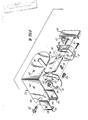
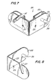
- the adjustable mounting device of this invention as shown in Fig. 6 comprises a reflector 10, L-shaped mounting straps 11, lampholders 12, mounting brackets 13, an L-shaped inner locking clamp 14 and an L-shaped outer locking clamp 15.
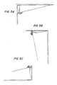
- Figs 5A, 5B and 5C depict typical mounting configurations of a luminaire with the adjustable mounting device of this invention.
- This invention can be adapted to additional mounting configurations. Whether the brackets are attached to the ceiling, wall, floor or similar surfaces, the installer can orient the brackets so that the luminaire always slides down into the slots 30, 31, 26, 27, 34 and 35, and is retained by gravity.
- each L-shaped mounting strap 16 is inserted into a channel in the reflector 17.
- Each mounting strap has an opening 18 for receiving a set screw 19 whereby each mounting strap is tightened against the reflector.
- Each lampholder 12 has two openings 20 which correspond to two openings in each mounting strap 21 whereby two internal screws 22 are used to connect each lampholder to each mounting strap.
- Both arms of the right end-of-run mounting bracket 43, left end-of-run mounting bracket 13 and intermediate mounting bracket 44 have openings 23, 24, 25 whereby one arm of each mounting bracket may be attached to a surface, such as a wall, ceiling, etc.
- the right end-of-run mounting bracket 43 has two arms. One arm has a shorter slot 26 which extends radially from the center of curvature at the end of the arm downward to the outer arc. The other arm has a longer slot 27 which extends diagonally upward and intersects beyond the curvature at the end of the arm. Through these slots, one arm of the right end-of-run bracket 43 may be connected with a mounting fulcrum screw 28 and a shoulder washer 29 to the mounting strap 11.
- the left end-of-run mounting bracket 13 has two arms. One arm has a shorter slot 30 which extends radially from the center of curvature at the end of the arm downward to the outer arc. The other arm has a longer slot 31 which extends diagonally upward and intersects beyond the curvature at the end of the arm. Through these slots, one arm of the left end-of-run bracket 13 may be connected with a mounting fulcrum screw 28 and a shoulder washer 29 to the mounting strap 11.
- the intermediate bracket 44 comprises two nested mounting brackets.
- the outer bracket 32 is identical to a left end-of-run mounting bracket 13.
- the inner bracket 33 is nested in and preferably spot-welded to the outer bracket 32, and has two inwardly offset arms which are parallel to the arms of the outer bracket 32.
- One pair of parallel arms has shorter slots 34 which extend radially from the center of curvature at the end of the arm downward to the outer arc.
- the other pair of parallel arms has longer slots 35 which extend diagonally upward and intersect beyond the curvature at the end of the arm.
- the arms of the intermediate mounting bracket 36 and 36a may be connected with mounting fulcrum screws 37 to the mounting straps 38 of two adjacently mounted luminaires, as depicted in Fig. 4.
- the L-shaped inner locking clamps 14 each have an opening 39
- the L-shaped outer locking clamps 15 each have a threaded opening 40 which corresponds to an opening in the mounting straps 41 whereby orientation locking screws 42 are used to connect the inner locking clamps 14 and the outer locking clamps 15 to the mounting straps 11.
- Adjustability of the reflector is accomplished when the orientation locking screws 42, inner locking clamps 14 and outer locking clamps 15 are loosened, thereby allowing the reflector to be rotated on the mounting fulcrum screws 28 resting in the slots 30, 31, 34, 35, 26 and 27 of the mounting brackets 13, 44, 43.
- locking is accomplished by tightening the orientation locking screws 42.
- the inner locking clamp 14 and outer locking clamp 15 cooperate to squeeze the mounting brackets 13, 44, 43 tightly and lock the reflector into position. Because this locking mechanism is offset from the long axis of the luminaire, the reflector may be locked into a desired rotational position with no subsequent loosening due to normal luminaire use and vibration.
- Reduction of dark spots in the lighting pattern created by adjacently mounted luminaires is accomplished by use of the intermediate mounting bracket 45 and 44.
- the nested structure of the intermediate mounting bracket allows two luminaires to be mounted adjacently with a minimal end-of-lamp interval 46 and 45.
- the small end-of-lamp interval results in the reduction of dark spots in the lighting pattern to nearly imperceptible levels.
Landscapes
- Engineering & Computer Science (AREA)
- General Engineering & Computer Science (AREA)
- Securing Globes, Refractors, Reflectors Or The Like (AREA)
- Fastening Of Light Sources Or Lamp Holders (AREA)
- Non-Portable Lighting Devices Or Systems Thereof (AREA)
- Control Of Position Or Direction (AREA)
Applications Claiming Priority (2)
| Application Number | Priority Date | Filing Date | Title |
|---|---|---|---|
| US07/053,045 US4881156A (en) | 1987-05-22 | 1987-05-22 | Adjustable mounting device for a luminaire |
| US53045 | 2002-01-15 |
Publications (2)
| Publication Number | Publication Date |
|---|---|
| EP0292093A2 true EP0292093A2 (fr) | 1988-11-23 |
| EP0292093A3 EP0292093A3 (fr) | 1989-09-27 |
Family
ID=21981579
Family Applications (1)
| Application Number | Title | Priority Date | Filing Date |
|---|---|---|---|
| EP88301986A Ceased EP0292093A3 (fr) | 1987-05-22 | 1988-03-08 | Montage réglable pour armature lumineuse |
Country Status (4)
| Country | Link |
|---|---|
| US (1) | US4881156A (fr) |
| EP (1) | EP0292093A3 (fr) |
| JP (1) | JPS63299005A (fr) |
| CA (1) | CA1289536C (fr) |
Families Citing this family (21)
| Publication number | Priority date | Publication date | Assignee | Title |
|---|---|---|---|---|
| US4992915A (en) * | 1989-10-04 | 1991-02-12 | Steelcraft Fluorescent Company | Lighting fixture having unitary fold-out lamp sockets |
| US5023765A (en) * | 1990-12-03 | 1991-06-11 | Barton Daniel W | Pivotable lamp bracket for linear lighting fixture |
| US5550725A (en) | 1994-11-03 | 1996-08-27 | Sylvan R. Shemitz Designs, Inc. | Adjustable luminaire and mounting system therefor |
| US6120163A (en) * | 1997-12-22 | 2000-09-19 | Woodhead Industries Inc. | Portable string hand lamp with removable mount |
| US6945675B2 (en) | 2002-01-04 | 2005-09-20 | Genlyte Thomas Group Llc | Fascia wash luminaire |
| US6644829B1 (en) | 2002-05-02 | 2003-11-11 | Optronics, Inc. | Rotatable light device and method |
| CA2411576C (fr) * | 2002-11-12 | 2007-08-14 | Delphitech Corporation | Boitier pour appareil d'eclairage a del et systeme d'eclairage de soffite utilisant ce boitier |
| US7249870B1 (en) | 2004-01-06 | 2007-07-31 | Electrix, Inc. | Light fixture having a housing with a channel for receiving a front element |
| US7465063B2 (en) | 2005-04-27 | 2008-12-16 | Stillman Allen M | Adjustable track lighting system adapted to support multiple types of light sources |
| US7658518B2 (en) * | 2005-08-03 | 2010-02-09 | Electrix, Inc. | Cove lighting |
| WO2007056298A2 (fr) * | 2005-11-04 | 2007-05-18 | Sylvan R. Shemitz Designs, Inc. | Ensemble de support de luminaire |
| US7494252B1 (en) | 2006-06-29 | 2009-02-24 | Genlyte Thomas Group Llc | Compact luminaire enclosure |
| US7946734B2 (en) | 2007-02-28 | 2011-05-24 | Philips Electronics Ltd | Low up-light cutoff acorn style luminaire |
| CA2623967C (fr) * | 2007-03-06 | 2015-11-24 | Canlyte Inc. | Luminaire avec reflecteur mixte |
| US20090129093A1 (en) * | 2007-11-19 | 2009-05-21 | Spi Lighting, Inc. | Shadow-free cove light |
| US7988327B1 (en) | 2009-01-30 | 2011-08-02 | Koninklijke Philips Electronics N.V. | LED luminaire |
| US9062840B2 (en) | 2012-05-24 | 2015-06-23 | Electrix, Llc | Cove lighting |
| US10808918B1 (en) | 2014-12-16 | 2020-10-20 | Electrix, Llc | Lighting fixture |
| US10180219B1 (en) | 2014-12-16 | 2019-01-15 | Electrix, Llc | Lighting fixture |
| US10598321B2 (en) | 2016-05-24 | 2020-03-24 | Electrix, Llc | Cove lighting |
| US10208933B1 (en) | 2017-08-08 | 2019-02-19 | Forum Lighting, Inc. | Adjustable light fixture and lighting system |
Family Cites Families (21)
| Publication number | Priority date | Publication date | Assignee | Title |
|---|---|---|---|---|
| DE437446C (de) * | 1926-11-20 | Rolf Rohmer | Lichtsoffitte | |
| US12795A (en) * | 1855-05-01 | Improved projectile for fire-arms | ||
| US2032791A (en) * | 1933-04-20 | 1936-03-03 | Gen Electric | Tubular and other incandescent lamps and their manufacture |
| US2382878A (en) * | 1944-02-03 | 1945-08-14 | Holecek Alois | Fluorescent desk lamp |
| US2740883A (en) * | 1953-05-11 | 1956-04-03 | A L Smith Iron Company | Combination lighting fixture and wiring conduit |
| US2922029A (en) * | 1956-11-23 | 1960-01-19 | Alfred M Eschelbach | Cornice bracket |
| US2905809A (en) * | 1957-01-14 | 1959-09-22 | Miller Co | Structure for mounting sockets and other devices in lighting fixtures |
| US3138418A (en) * | 1961-12-05 | 1964-06-23 | Gen Electric | Fastening means for securing a fluorescent lampholder to a panel |
| US3265886A (en) * | 1963-12-30 | 1966-08-09 | Westinghouse Electric Corp | Fluorescent luminaire |
| US3599911A (en) * | 1969-11-06 | 1971-08-17 | Sunbeam Lighting Co Inc | Means for end-to-end assembly of elongated fluorescent lamp ceiling fixtures |
| US3955078A (en) * | 1974-09-06 | 1976-05-04 | Eggers Larry A | Multi-purpose fishing light |
| CA1061759A (fr) * | 1977-02-25 | 1979-09-04 | Gerard E. Mulvey | Appareil d'eclairage |
| US4177504A (en) * | 1977-11-04 | 1979-12-04 | General Electric Company | Luminaire reflector mounting for rotation of asymmetric reflector |
| JPS5943544Y2 (ja) * | 1979-01-22 | 1984-12-25 | 道雄 川添 | カメラ取付用ブラケツトの保持装置 |
| US4245284A (en) * | 1979-06-13 | 1981-01-13 | Union Insulating Company | Electric lighting fixture and globe support |
| DE2951545A1 (de) * | 1979-12-21 | 1981-07-02 | Hermann 8500 Nürnberg Leber | Langfeldleuchte |
| US4368506A (en) * | 1980-12-08 | 1983-01-11 | Gardco Manufacturing, Inc. | Apparatus for mounting a luminaire to a ceiling |
| GB2113817B (en) * | 1982-01-18 | 1985-05-30 | Philips Electronic Associated | Optical apparatus |
| US4480809A (en) * | 1982-09-22 | 1984-11-06 | Lowrance Electronics, Inc. | Gimbal bracket mounting for instrument |
| US4535393A (en) * | 1983-11-10 | 1985-08-13 | Jahabow Industries, Inc. | Fluorescent lamp housing |
| DE8514281U1 (de) * | 1985-05-14 | 1985-06-20 | Marketing-Dienste Trilk, 8772 Marktheidenfeld | Lampe mit schwenkbarer Reflektorblende |
-
1987
- 1987-05-22 US US07/053,045 patent/US4881156A/en not_active Expired - Fee Related
-
1988
- 1988-03-08 EP EP88301986A patent/EP0292093A3/fr not_active Ceased
- 1988-04-28 CA CA000565332A patent/CA1289536C/fr not_active Expired - Fee Related
- 1988-05-12 JP JP63113723A patent/JPS63299005A/ja active Pending
Also Published As
| Publication number | Publication date |
|---|---|
| JPS63299005A (ja) | 1988-12-06 |
| US4881156A (en) | 1989-11-14 |
| CA1289536C (fr) | 1991-09-24 |
| EP0292093A3 (fr) | 1989-09-27 |
Similar Documents
| Publication | Publication Date | Title |
|---|---|---|
| US4881156A (en) | Adjustable mounting device for a luminaire | |
| US5788518A (en) | Adjustable connector for track lighting fixture | |
| US6481871B2 (en) | Adjustable lamp support | |
| US6652124B2 (en) | Lamp-independent adjustable recessed light fixture | |
| US3561719A (en) | Light fixture support | |
| US5258899A (en) | Motion sensor lighting control | |
| US5672003A (en) | Universal track light mounting system | |
| US5593224A (en) | Field-adjustable internal pivot tension device | |
| US4453204A (en) | Support assembly for lamp swing arm | |
| US6502967B2 (en) | Gimble ring lighting fixture support | |
| US8727583B2 (en) | Lamp alignment assembly and lighting device | |
| US5124901A (en) | Sloping ceiling adapter for recessed lighting | |
| US8021013B2 (en) | Lighting assembly with aperture alignment assembly | |
| CA2177911A1 (fr) | Appareil d'eclairage encastre | |
| US6979108B1 (en) | Multi-use adaptor kit/system for recessed can fixtures | |
| US5130914A (en) | Light fixture assembly | |
| US5550725A (en) | Adjustable luminaire and mounting system therefor | |
| US6702453B2 (en) | Flexible light fixture | |
| JP2002501659A (ja) | 二重反射がさ照明装置 | |
| US3299797A (en) | Combined air diffuser and lighting fixture | |
| US5704710A (en) | Lighting fixture with a safety hook | |
| US6007217A (en) | Luminaire assembly mounting system | |
| JP2002517880A (ja) | 照明装置 | |
| EP0089713B1 (fr) | Armature lumineuse | |
| JP3858322B2 (ja) | 天井埋め込み型照明器具 |
Legal Events
| Date | Code | Title | Description |
|---|---|---|---|
| PUAI | Public reference made under article 153(3) epc to a published international application that has entered the european phase |
Free format text: ORIGINAL CODE: 0009012 |
|
| AK | Designated contracting states |
Kind code of ref document: A2 Designated state(s): BE DE ES FR GB GR IT LU NL |
|
| PUAL | Search report despatched |
Free format text: ORIGINAL CODE: 0009013 |
|
| AK | Designated contracting states |
Kind code of ref document: A3 Designated state(s): BE DE ES FR GB GR IT LU NL |
|
| 17P | Request for examination filed |
Effective date: 19900321 |
|
| 17Q | First examination report despatched |
Effective date: 19910820 |
|
| STAA | Information on the status of an ep patent application or granted ep patent |
Free format text: STATUS: THE APPLICATION HAS BEEN REFUSED |
|
| 18R | Application refused |
Effective date: 19930424 |