EP0295771B1 - Apparat und Verfahren zur schnellen Bestimmung eines Hämatokrit-Wertes - Google Patents
Apparat und Verfahren zur schnellen Bestimmung eines Hämatokrit-Wertes Download PDFInfo
- Publication number
- EP0295771B1 EP0295771B1 EP88303478A EP88303478A EP0295771B1 EP 0295771 B1 EP0295771 B1 EP 0295771B1 EP 88303478 A EP88303478 A EP 88303478A EP 88303478 A EP88303478 A EP 88303478A EP 0295771 B1 EP0295771 B1 EP 0295771B1
- Authority
- EP
- European Patent Office
- Prior art keywords
- voltage
- electric motor
- electronic circuit
- disabling
- battery
- Prior art date
- Legal status (The legal status is an assumption and is not a legal conclusion. Google has not performed a legal analysis and makes no representation as to the accuracy of the status listed.)
- Expired - Lifetime
Links
- 238000000034 method Methods 0.000 title claims description 13
- 238000005534 hematocrit Methods 0.000 title description 32
- 230000001133 acceleration Effects 0.000 claims abstract description 21
- 238000005119 centrifugation Methods 0.000 claims abstract description 12
- 238000012360 testing method Methods 0.000 claims abstract description 11
- 239000012530 fluid Substances 0.000 claims abstract description 8
- 230000009849 deactivation Effects 0.000 claims abstract description 7
- 230000001154 acute effect Effects 0.000 claims abstract description 4
- 239000000725 suspension Substances 0.000 claims abstract description 4
- 230000011664 signaling Effects 0.000 claims description 4
- 230000000873 masking effect Effects 0.000 claims 3
- 210000004027 cell Anatomy 0.000 description 15
- 239000002245 particle Substances 0.000 description 14
- 239000008280 blood Substances 0.000 description 12
- 210000004369 blood Anatomy 0.000 description 11
- 238000004062 sedimentation Methods 0.000 description 7
- 238000000926 separation method Methods 0.000 description 6
- 210000000601 blood cell Anatomy 0.000 description 4
- 230000000694 effects Effects 0.000 description 4
- 238000002474 experimental method Methods 0.000 description 3
- 239000003814 drug Substances 0.000 description 2
- 239000002609 medium Substances 0.000 description 2
- 239000013049 sediment Substances 0.000 description 2
- 210000004128 D cell Anatomy 0.000 description 1
- 238000009534 blood test Methods 0.000 description 1
- 230000008614 cellular interaction Effects 0.000 description 1
- 238000004140 cleaning Methods 0.000 description 1
- 230000001419 dependent effect Effects 0.000 description 1
- 230000000994 depressogenic effect Effects 0.000 description 1
- 238000001514 detection method Methods 0.000 description 1
- 238000010586 diagram Methods 0.000 description 1
- 210000003743 erythrocyte Anatomy 0.000 description 1
- 239000001963 growth medium Substances 0.000 description 1
- 238000003754 machining Methods 0.000 description 1
- 230000013011 mating Effects 0.000 description 1
- 238000012856 packing Methods 0.000 description 1
- 238000003825 pressing Methods 0.000 description 1
- 238000012545 processing Methods 0.000 description 1
- 238000005096 rolling process Methods 0.000 description 1
- 210000002966 serum Anatomy 0.000 description 1
- 239000002002 slurry Substances 0.000 description 1
- 239000012798 spherical particle Substances 0.000 description 1
- 239000006228 supernatant Substances 0.000 description 1
- 230000000007 visual effect Effects 0.000 description 1
- 238000005406 washing Methods 0.000 description 1
Images


Classifications
-
- B—PERFORMING OPERATIONS; TRANSPORTING
- B04—CENTRIFUGAL APPARATUS OR MACHINES FOR CARRYING-OUT PHYSICAL OR CHEMICAL PROCESSES
- B04B—CENTRIFUGES
- B04B9/00—Drives specially designed for centrifuges; Arrangement or disposition of transmission gearing; Suspending or balancing rotary bowls
- B04B9/02—Electric motor drives
-
- B—PERFORMING OPERATIONS; TRANSPORTING
- B04—CENTRIFUGAL APPARATUS OR MACHINES FOR CARRYING-OUT PHYSICAL OR CHEMICAL PROCESSES
- B04B—CENTRIFUGES
- B04B5/00—Other centrifuges
- B04B5/04—Radial chamber apparatus for separating predominantly liquid mixtures, e.g. butyrometers
- B04B5/0407—Radial chamber apparatus for separating predominantly liquid mixtures, e.g. butyrometers for liquids contained in receptacles
- B04B5/0414—Radial chamber apparatus for separating predominantly liquid mixtures, e.g. butyrometers for liquids contained in receptacles comprising test tubes
Definitions
- This invention relates to hematocrit apparatus and methods and, more particularly to hematocrit apparatus and methods for obtaining a rapid hematocrit.
- Hematocrit determinations are used extensively within the field of medicine and involve obtaining a small sample of blood from a patient.
- the blood sample is drawn into a tube, known as the hematocrit tube, and the tube is then placed in a centrifuge apparatus where the blood sample is subjected to very high acceleration forces to cause the blood cells to be packed into the bottom of the tube.
- the hematocrit tube is examined and the ratio of serum above the packed cell volume (PCV) is compared with standard charts to give to the medical personnel the desired information regarding the blood sample.
- PCV ratio of serum above the packed cell volume
- US-A-3 233 825 provides a hand-held centrifuge apparatus and a method of subjecting a fluid sample to a predetermined centrifugation force in accordance with the prior art portions of claims 1 and 4, respectively.
- the present invention provides for assurance that the requisite centrifuging speed has been attained by ensuring that the apparatus is only operable when a preselected rotational speed can be used for a predetermined time, the required rotational speed being ensured by checking that the voltage of the battery supply is at a predetermined level.
- a signal system provides an indication when the centrifugation cycle has been completed with means being provided for ensuring that the effect of low voltage is masked during acceleration of the rotor when the loading on the motor due to the acceleration will cause a lower voltage to be sensed.
- GB-A-1 155 263 discloses means for deactivating a motor when a voltage drops too low, this is in connection with a battery powered industrial truck and has no appreciation of the need to mask a voltage drop during acceleration which occurs with the small hand-held battery powered centrifuge of the invention.
- the present invention provides a hand-held centrifuge apparatus for providing hematocrit readings at remote locations.
- Another object of this invention is to provide a relatively rapid method for obtaining hematocrit readings.
- Another object of this invention is to provide a method for obtaining hematocrit readings at remote locations.
- Separation of particles from a suspending fluid is a technique fundamental to many areas of medicine and biotechnology. There is an increasing need to shorten the time necessary to effect such separation. For example, there are an increasing number of home tests that require red blood cell free plasma. Larger scale rapid separations are required for the processing of unit quantities of whole blood or the washing of glycerolized frozen blood. Numerous biotechnology applications arise including the removal of cells from a suspending growth medium.
- the fundamental tool used to effect separation is the centrifuge, a device that creates acceleration by rotational motion. This acceleration acts on particles whose density is different than that of the suspending medium. The particles then move through the medium at a velocity dependent on the density difference, fluid viscosity, local acceleration and particle size.
- the fluid suspension of particles is placed in an elongated, closed-end tube.
- the tube is mounted in a commercially available centrifuge apparatus which radially spins the tube in a plane perpendicular to the axis of rotation.
- the rotation rate for such a conventional device is in the thousands of revolutions per minute.
- the time required for sedimentation of the particles is an extended time, both the rate and time of rotation are a function of the nature of the suspension and the analytical protocal. Since the tubes are arrayed radially around the axis of rotation the devices tend to be rather large which, in turn, coupled with the high rotational speeds, means that the conventional centrifuge apparatus is usually quite expensive due to the requirement for precision machining to achieve the necessary balance, etc.
- the angle of the tubes was changed with respect to the rotational axis.
- the tubes were placed at an acute angle to the rotational axis to reduce the diameter of the centrifuge head. Times of about one minute were obtained. Unexpectedly, shorter sedimentation times were obtained at relatively low rpm.
- the cells were packed in the microhematocrit tube in one minute and at about 1/3 the acceleration used in conventional centrifuges. Further, the packed cell volume (PCV) obtained in one minute is equivalent to the PCV obtained only after thirty minutes in the conventional centrifuge.
- centrifugation will allow the rapid separation of blood from plasma in microhematocrit tubes thus providing plasma for the myriad of blood tests. Further, because the separation is done at low speed, simple low cost centrifuges can be used. In fact, a small centrifuge has been constructed that uses an inexpensive motor powered by two dry cells and a simple plastic head.
- the buoyant force on a particle is given by; where G is the local acceleration, rho-p is the particle density and rho-f is the fluid density.
- Standard microhematocrit centrifuge has a disk-shaped head that rotates the axis of the hematocrit tubes normal to the axis of rotation of the head. Thus the blood cells must traverse half the length of the tube (assuming 50% PCV). For a typical microhematocrit tube this amounts to approximately 35000 micrometers.
- Figure 5 shows PCV as a function of time obtained from a standard microhematocrit centrifuge operating at 11500 rpm. Note that equilibrium values are obtained only after times in excess of thirty minutes. Although Equation 1 predicts sedimentation times of the order of second for this angular velocity, blood cell-blood cell interactions, nonspheroidal blood cell shape and other hydrodynamic factors combine to produce these long real life sedimentation times.
- Figure 6 shows the PCV fraction as a function of time obtained at lower rpm in tubes whose axis has been rotated 70 degrees from the plane normal to the rotational axis of the head.
- the radian velocity of the center of the tube has been reduced to 315 rad/s compared to 1200 rad/s in the standard centrifuge. Note, however, that equilibrium values are achieved at times of about one minute. Similar equilibrium values are obtained in two to three minutes at a radian velocity of 190 rad/s.
- the distance to the center of the tube from the axis of rotation is 3 cm in the angled tube head and 3.5 cm in the standard head so that the local acceleration on the particle is proportional to w these experiments (the standard head should have a slight advantage).
- Figure 7 diagrammatically illustrates the forces acting on cells in the angled head.
- the maximum distance a cell can travel is the inside diameter of the tube.
- the maximum distance a cell can travel is the length of the tube.
- the graph in Figure 7 shows that for tubes at large angles from the normal to the rotation axis, the distance a cell may travel is close to the tube diameter (560 micrometers) and hence the sedimentation time is short. When the angle is small the distance is 35000 um and the sedimentation time is longer.
- Figure 9 shows that for an angle of 70 degrees, 3000 rpm in this sized head produces almost equilibrium value hematocrits in one minute.
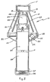
- housing 12 is fabricated with a frustoconical configuration have an upper end 16 terminating in an open, cylindrical neck 18 (closed by a cap 17) and a lower end lower to a mating, frustoconical base 20 along a joint 22.
- housing 12 and base 20 provides an enclosure 23 for various components of this invention including, for example, motor 24, rotor 26, tube supports 28 and 29, circuit board 30 and switch 32. Access for placement and retrieval of hematocrit tubes (not shown) in tube supports 28 and 29 is provided through a throat 19 adjacent the base of neck 18. Each of tube supports 28 and 29 are removable from rotor 26 to facilitate cleaning, etc., of the particular tube support.
- Motor 24 and switch 32 (actuated upon pressing button 33) are commercially available components compatible for operation with two conventional, D-cell batteries 34 and 35.
- Handle 14 serves as the receiving chamber for batteries 34 and 35 as well as providing the necessary hand gripping surface for hand-held centrifuge 10.
- a cap 36 provides access to batteries 34 and 35 inside handle 14 while a spring 37 inside a cap 36 assures appropriate electrical contact for batteries 34 and 35.
- a faceted buttress 38 ( Figure 1) formed around joint 22 provides a plurality of facets upon which hand-held centrifuge 10 can be rested to preclude inadvertently rolling of hand-held centrifuge 10.
- a tether 15 secures cap 17 to neck 18 while a tether 39 secures cap 36 to handle 14, both of tethers 15 and 39 preventing the inadvertent loss or misplacement of the respective caps 17 and 36.
- Signal lights 40 and 42 provide the desired visual indication to the operator (not shown) of the condition of hand-held centrifuge 10.
- signal light 40 is a red light that is illuminated when the circuitry (see Figure 4) determines that hand-held centrifuge is in an inoperative condition such as low battery, etc.
- Signal light 42 is a green light and is illuminated when hand-held centrifuge 10 is operating.
- FIG. 4 a schematic of the circuitry for circuit board 30 ( Figure 3) is shown and includes switch 32 and supporting circuitry to implement single button operation.
- the button 33 ( Figures 1-3) of switch 32 is debounced and connected to the clock input of a "T" flip flop 44.
- the Q* output of flip flop 44 controls the gate voltage of a MOSFET transistor 46.
- This MOSFET 46 when turned on, provides a current path through the DC motor 24 while dropping very little voltage itself. Since the MOSFET gate to source threshold voltage requires greater than about five volts for proper operation, the circuit employs a voltage doubler 48 to boost the gate voltage so a three volt battery can be employed.
- a timing chip 50 provides three signals: the Q14, Q12 and Q6 outputs.
- a pulse on Q14 signals the end of the centrifugation run, and at set intervals during the run the Q12 output enables the voltage test circuitry. If the battery voltage drops and the run is aborted, the Q6 output causes the D2 LED (signal light 40) to flash. The functioning of these outputs is discussed below.
- the Q14 output of timing chip 50 is connected to the clear input of the "T" flip flop 44 and ends the centrifugation run by bringing this input low.
- the time interval before Q14 is asserted and is set by the RC time constant of R t x C t .
- timing chip 50 enables the voltage test circuitry into the preset input of the JK flip flop 52 at set times during the centrifugation run. If the battery voltage drops to a point where the rotor speed is inadequate, the threshold voltage detector will output a low signal. This signal is masked out until the Q12 output is also asserted. This feature allows the battery voltage to drop temporarily during motor acceleration without aborting the run.
- the JK flip flop 52 is clocked so that Q JK output "clears” the "T” flip flop 44 and so deactivates motor 24, voltage doubling circuitry 48, and threshold voltage detection circuitry.
- the JK flip flop 52 Q output also overrides the "T” flip flop 44 deactivation of timing chip 50 and maintains this chip's operation.
- the JK flip flop 52 Q* output enables the timing chip 50 Q6 output into the D2 LED 40, causing it to flash, signalling a low battery aborted run. Once the low battery LED 40 begins flashing, the pushbutton has no effect and the D2 LED 40 will flash indefinitely until the batteries are removed and replaced. This feature prevents operation of the system if the batteries and rotor speed are substandard.
- Pushing the on/off button while the motor is on will clock the "T" flip flop 44 and terminate the run.
- FIG 10 an enlargement of the chart for obtaining a hematocrit reading is shown.
- This chart is selectively reduced and wrapped around handle 14 ( Figures 1-3) so as to present the chart in an easily accessible configuration.
- the chart is prepared with a sloping line indicating 100% or the total volume of the sample.
- the upper and lower limits of the sample are aligned with the 100% and bottom lines, respectively, of the chart so that the line representing the volume of sediment in the tube can be read directly from the chart.
Landscapes
- Centrifugal Separators (AREA)
- Investigating Or Analysing Biological Materials (AREA)
Claims (5)
- Handgeführte Zentrifugiervorrichtung, umfassend ein Gehäuse (12); einen Handgriff (14), der an dem Gehäuse befestigt ist; einen Elektromotor (24) in dem Gehäuse; und einen Rotor (26), der drehbar auf dem Motor (24) gelagert ist und in dem Gehäuse (12) drehbar ist, wobei der Rotor mindestens einen Kalter (28, 29) für ein Probenröhrchen aufweist, und der Kalter im spitzen Winkel zur Drehachse des Rotors angeordnet ist, wobei der Handgriff einen Behälter für mindestens eine Batterie (34, 35) aufweist, die den Elektromotor antreibt; dadurch gekennzeichnet, daß eine elektronische Schaltung (30) vorgesehen ist, die den Betrieb des Elektromotors (24) steuert, wobei die elektronische Schaltung eine Spannungstesteinrichtung (Q12, 52) aufweist, die die Spannung in der elektronischen Schaltung prüft, um festzustellen, ob genügend Spannung von der Batterie oder den Batterien (34, 35) zu dem Elektromotor (24) geleitet wird, eine Deaktivierungseinrichtung (52, JKQ, 44), die den Elektromotor (24) außer Betrieb setzt, wenn die Spannungstesteinrichtung eine unzureichende Spannung feststellt, eine Signaleinrichtung (40), die ein Signal erzeugt, wenn die Deaktivierungseinrichtung den Elektromotor außer Betrieb gesetzt hat, und eine Abschalteinrichtung (52Q, 50), die die elektronische Schaltung abschaltet, wenn die Deaktivierungseinrichtung den Elektromotor außer Betrieb gesetzt hat, wobei die Abschalteinrichtung die elektronische Schaltung in einem abgeschalteten Zustand hält, bis eine ausreichende Spannung durch die Batterie zugeführt wird, wobei die Abschalteinrichtung eine Maskierungseinrichtung (50) umfaßt, die die Abschalteinrichtung (Q12) während der Beschleunigung des Elektromotors (24) ausblendet, um dadurch zu verhindern, daß der Elektromotor versehentlich außer Betrieb gesetzt wird, wenn die Rotordrehzahl während der Beschleunigung ausreichend ist.
- Handgeführte Zentrifugiervorrichtung nach Anspruch 1, dadurch gekennzeichnet, daß die elektronische Schaltung eine Zeitgebereinrichtung (50, Q14) umfaßt, wobei die Zeitgebereinrichtung mit der Spannungstesteinrichtung zusammenwirkt, um den Elektromotor (24) für eine vorbestimmte Zeit bei einer vorgewählten Spannung zu betätigen, wodurch sichergestellt ist, daß ein Probenröhrchen, das in dem Kalter (28, 29) auf dem Rotor (26) gehalten ist, einer vorbestimmten Zentrifugalkraft ausgesetzt war.
- Handgeführte Zentrifugiervorrichtung nach Anspruch 1 oder 2, dadurch gekennzeichnet, daß die elektronische Schaltung einen Spannungsverdoppler (48) umfaßt, der die Gate-Spannung, die an einem MOSFET (46) in der elektronischen Schaltung anliegt, verstärkt, so daß der Einsatz einer Batterie (34, 35) mit niedrigerer Spannung möglich ist.
- Verfahren, mit dem eine Probe einer Flüssigkeitssuspension einer vorbestimmten Zentrifugalkraft an einer von einer elektrischen Stromquelle entfernten Stelle ausgesetzt wird, umfassend die folgenden Schritte: Vorsehen einer handgeführten Zentrifugiervorrichtung umfassend ein Gehäuse (12), einen Handgriff (14), der an dem Gehäuse befestigt ist, wobei der Handgriff einen Behälter für mindestens eine Batterie (34, 35) bildet, einen Elektromotor (24) in dem Gehäuse (12) mit einem an dem Motor (24) befestigten Rotor (26) und einem Probenröhrchenhalter (28, 29), wobei der Probenröhrchenhalter im spitzen Winkel zu der Drehachse des Rotors angeordnet ist; dadurch gekennzeichnet, daß der Betrieb des Elektromotors über eine elektronische Schaltung (30) gesteuert wird, die eine Spannungstesteinrichtung (Q12, 52) zum Testen der Spannung in der elektronischen Schaltung aufweist, eine Deaktivierungseinrichtung (52, JKQ, 44), die den Elektromotor (24) außer Betrieb setzt, wenn die Spannung unter einem vorgewählten Wert liegt, eine Abschalteinrichtung (52Q, 50), die die elektronische Schaltung abschaltet, bis der elektronischen Schaltung eine ausreichende Spannung zugeführt wird, eine Signalerzeugungseinrichtung (40), die ein Signal erzeugt, wenn die Abschalteinrichtung in Betrieb ist, und eine Zeitgebereinrichtung (50, Q14), die mit der Spannungstesteinrichtung (Q12) zusammenwirkt, um den Elektromotor (24) für eine vorbestimmte Zeit bei einer vorgewählten Spannung zu betätigen, wodurch sichergestellt ist, daß ein in dem Probenröhrchenhalter gehaltenes Probenröhrchen einem vorbestimmten Zentrifugiergrad ausgesetzt ist, und daß der Schritt des Steuerns das Ausblenden der Abschalteinrichtung (Q12) während der Beschleunigung des Elektromotors (24) umfaßt, wodurch verhindert wird, daß der Elektromotor (24) während der Beschleunigung außer Betrieb gesetzt wird.
- Verfahren nach Anspruch 4, dadurch gekennzeichnet, daß der Schritt des Steuerns die Verstärkung einer an einen MOSFET (46) angelegten Gate-Spannung unter Verwendung eines Spannungsverdopplers (48) in der elektronischen Schaltung umfaßt, wodurch der Einsatz einer Batterie mit niedrigerer Spannung möglich ist.
Priority Applications (1)
| Application Number | Priority Date | Filing Date | Title |
|---|---|---|---|
| AT88303478T ATE81607T1 (de) | 1987-06-17 | 1988-04-18 | Apparat und verfahren zur schnellen bestimmung eines haematokrit-wertes. |
Applications Claiming Priority (2)
| Application Number | Priority Date | Filing Date | Title |
|---|---|---|---|
| US07/063,488 US4738655A (en) | 1987-06-17 | 1987-06-17 | Apparatus and method for obtaining a rapid hematocrit |
| US63488 | 1987-06-17 |
Publications (3)
| Publication Number | Publication Date |
|---|---|
| EP0295771A2 EP0295771A2 (de) | 1988-12-21 |
| EP0295771A3 EP0295771A3 (en) | 1990-01-24 |
| EP0295771B1 true EP0295771B1 (de) | 1992-10-21 |
Family
ID=22049547
Family Applications (1)
| Application Number | Title | Priority Date | Filing Date |
|---|---|---|---|
| EP88303478A Expired - Lifetime EP0295771B1 (de) | 1987-06-17 | 1988-04-18 | Apparat und Verfahren zur schnellen Bestimmung eines Hämatokrit-Wertes |
Country Status (8)
| Country | Link |
|---|---|
| US (1) | US4738655A (de) |
| EP (1) | EP0295771B1 (de) |
| JP (1) | JPS6454256A (de) |
| AT (1) | ATE81607T1 (de) |
| AU (1) | AU600574B2 (de) |
| CA (1) | CA1324117C (de) |
| DE (1) | DE3875389T2 (de) |
| ES (1) | ES2035918T3 (de) |
Cited By (19)
| Publication number | Priority date | Publication date | Assignee | Title |
|---|---|---|---|---|
| US7374678B2 (en) | 2002-05-24 | 2008-05-20 | Biomet Biologics, Inc. | Apparatus and method for separating and concentrating fluids containing multiple components |
| US7470371B2 (en) | 2002-05-03 | 2008-12-30 | Hanuman Llc | Methods and apparatus for isolating platelets from blood |
| US7708152B2 (en) | 2005-02-07 | 2010-05-04 | Hanuman Llc | Method and apparatus for preparing platelet rich plasma and concentrates thereof |
| US7780860B2 (en) | 2002-05-24 | 2010-08-24 | Biomet Biologics, Llc | Apparatus and method for separating and concentrating fluids containing multiple components |
| US7806276B2 (en) | 2007-04-12 | 2010-10-05 | Hanuman, Llc | Buoy suspension fractionation system |
| US7832566B2 (en) | 2002-05-24 | 2010-11-16 | Biomet Biologics, Llc | Method and apparatus for separating and concentrating a component from a multi-component material including macroparticles |
| US7845499B2 (en) | 2002-05-24 | 2010-12-07 | Biomet Biologics, Llc | Apparatus and method for separating and concentrating fluids containing multiple components |
| US7992725B2 (en) | 2002-05-03 | 2011-08-09 | Biomet Biologics, Llc | Buoy suspension fractionation system |
| US8012077B2 (en) | 2008-05-23 | 2011-09-06 | Biomet Biologics, Llc | Blood separating device |
| US8096422B2 (en) | 2005-02-07 | 2012-01-17 | Hanuman Llc | Apparatus and method for preparing platelet rich plasma and concentrates thereof |
| US8105495B2 (en) | 2005-02-07 | 2012-01-31 | Hanuman, Llc | Method for preparing platelet rich plasma and concentrates thereof |
| US8187475B2 (en) | 2009-03-06 | 2012-05-29 | Biomet Biologics, Llc | Method and apparatus for producing autologous thrombin |
| US8313954B2 (en) | 2009-04-03 | 2012-11-20 | Biomet Biologics, Llc | All-in-one means of separating blood components |
| US8328024B2 (en) | 2007-04-12 | 2012-12-11 | Hanuman, Llc | Buoy suspension fractionation system |
| US8337711B2 (en) | 2008-02-29 | 2012-12-25 | Biomet Biologics, Llc | System and process for separating a material |
| US8567609B2 (en) | 2006-05-25 | 2013-10-29 | Biomet Biologics, Llc | Apparatus and method for separating and concentrating fluids containing multiple components |
| US8591391B2 (en) | 2010-04-12 | 2013-11-26 | Biomet Biologics, Llc | Method and apparatus for separating a material |
| US9011800B2 (en) | 2009-07-16 | 2015-04-21 | Biomet Biologics, Llc | Method and apparatus for separating biological materials |
| US9556243B2 (en) | 2013-03-15 | 2017-01-31 | Biomet Biologies, LLC | Methods for making cytokine compositions from tissues using non-centrifugal methods |
Families Citing this family (30)
| Publication number | Priority date | Publication date | Assignee | Title |
|---|---|---|---|---|
| US5526808A (en) * | 1990-10-04 | 1996-06-18 | Microcor, Inc. | Method and apparatus for noninvasively determining hematocrit |
| US5642734A (en) * | 1990-10-04 | 1997-07-01 | Microcor, Inc. | Method and apparatus for noninvasively determining hematocrit |
| US5354254A (en) * | 1993-04-15 | 1994-10-11 | Separation Technology, Inc. | Centrifuge rotor head with tube neck support |
| US5605529A (en) * | 1996-01-17 | 1997-02-25 | Norfolk Scientific, Inc. | High efficiency centrifuge rotor |
| US5924972A (en) * | 1998-03-24 | 1999-07-20 | Turvaville; L. Jackson | Portable D.C. powered centrifuge |
| EP1458488B1 (de) * | 2000-11-02 | 2011-12-21 | CaridianBCT, Inc. | Vorrichtungen, systeme und verfahren zur fluidtrennung |
| DE10202603B4 (de) | 2002-01-24 | 2012-08-30 | Robert Bosch Gmbh | Verfahren und Vorrichtung zur Verlangsamung des Entladungsprozesses eines Akkus |
| WO2003086640A1 (en) * | 2002-04-12 | 2003-10-23 | Gambro, Inc. | Fluid separation using a centrifuge and roller pump |
| US20060278588A1 (en) | 2002-05-24 | 2006-12-14 | Woodell-May Jennifer E | Apparatus and method for separating and concentrating fluids containing multiple components |
| US6905454B2 (en) * | 2002-06-28 | 2005-06-14 | The United States Of America As Represented By The Secretary Of The Army | Handheld and hand-powered centrifuge device |
| JP2004333219A (ja) * | 2003-05-02 | 2004-11-25 | Yuichi Shimoyama | 遠心分離機 |
| US7494814B2 (en) | 2004-07-13 | 2009-02-24 | Separation Technology, Inc. | Apparatus and method for obtaining rapid creamatocrit and caloric content values of milk |
| EP2620139B1 (de) | 2008-02-27 | 2016-07-20 | Biomet Biologics, LLC | Interleukin-1-Rezeptorantagonisten-reiche Lösungen |
| NL1035244C2 (nl) * | 2008-04-02 | 2009-10-05 | Jan Hessels | Automatisch gebalanceerde microcentrifuge device met minimotor en methode voor verzamelen en centrifugeren van bloed en voor stabiliseren en bewaren van plasma/serum in hetzelfde device. |
| US8177072B2 (en) | 2008-12-04 | 2012-05-15 | Thermogenesis Corp. | Apparatus and method for separating and isolating components of a biological fluid |
| US8986185B2 (en) * | 2009-09-24 | 2015-03-24 | Lipovera, Llc | Syringe centrifuge systems |
| US20130265417A1 (en) * | 2012-04-09 | 2013-10-10 | Western New England University | Centrifuge |
| US9642956B2 (en) | 2012-08-27 | 2017-05-09 | Biomet Biologics, Llc | Apparatus and method for separating and concentrating fluids containing multiple components |
| US9248446B2 (en) | 2013-02-18 | 2016-02-02 | Terumo Bct, Inc. | System for blood separation with a separation chamber having an internal gravity valve |
| WO2014160125A1 (en) * | 2013-03-14 | 2014-10-02 | Centricycle, Inc. | Centrifuge device |
| US10143725B2 (en) | 2013-03-15 | 2018-12-04 | Biomet Biologics, Llc | Treatment of pain using protein solutions |
| US9895418B2 (en) | 2013-03-15 | 2018-02-20 | Biomet Biologics, Llc | Treatment of peripheral vascular disease using protein solutions |
| US20140271589A1 (en) | 2013-03-15 | 2014-09-18 | Biomet Biologics, Llc | Treatment of collagen defects using protein solutions |
| US9950035B2 (en) | 2013-03-15 | 2018-04-24 | Biomet Biologics, Llc | Methods and non-immunogenic compositions for treating inflammatory disorders |
| US9713810B2 (en) | 2015-03-30 | 2017-07-25 | Biomet Biologics, Llc | Cell washing plunger using centrifugal force |
| US9757721B2 (en) | 2015-05-11 | 2017-09-12 | Biomet Biologics, Llc | Cell washing plunger using centrifugal force |
| CN109046804B (zh) * | 2018-07-20 | 2021-03-30 | 湘潭惠博离心机有限公司 | 机械推料离心机推料驱动装置 |
| US20230381792A1 (en) * | 2019-03-11 | 2023-11-30 | ABC Med Tech Corp. | Portable Centrifuge Apparatus & Methods |
| US12558463B2 (en) * | 2019-03-11 | 2026-02-24 | ABC Med Tech Corp. | Portable centrifuge device and method of use |
| US20230321671A1 (en) * | 2022-04-08 | 2023-10-12 | Arthrex, Inc. | Systems and methods for motor source driven biological sample processing |
Family Cites Families (5)
| Publication number | Priority date | Publication date | Assignee | Title |
|---|---|---|---|---|
| US3233825A (en) * | 1963-02-11 | 1966-02-08 | Lomb Paul | Self-contained centrifuge |
| GB1155263A (en) * | 1965-04-15 | 1969-06-18 | Clark Stacatruc Ltd | Improvements in or relating to Control Circuits for Battery-Powered Trucks. |
| US3567113A (en) * | 1969-03-18 | 1971-03-02 | Us Air Force | Miniature, portable, self-powered, high speed, clinical centrifuge |
| JPS57937Y2 (de) * | 1978-03-13 | 1982-01-07 | ||
| US4226669A (en) * | 1979-05-09 | 1980-10-07 | Savant Instruments, Inc. | Vacuum centrifuge with magnetic drive |
-
1987
- 1987-06-17 US US07/063,488 patent/US4738655A/en not_active Expired - Lifetime
-
1988
- 1988-04-18 DE DE8888303478T patent/DE3875389T2/de not_active Expired - Fee Related
- 1988-04-18 ES ES198888303478T patent/ES2035918T3/es not_active Expired - Lifetime
- 1988-04-18 CA CA000564419A patent/CA1324117C/en not_active Expired - Lifetime
- 1988-04-18 EP EP88303478A patent/EP0295771B1/de not_active Expired - Lifetime
- 1988-04-18 AT AT88303478T patent/ATE81607T1/de not_active IP Right Cessation
- 1988-04-19 AU AU14751/88A patent/AU600574B2/en not_active Ceased
- 1988-05-17 JP JP63120407A patent/JPS6454256A/ja active Pending
Cited By (38)
| Publication number | Priority date | Publication date | Assignee | Title |
|---|---|---|---|---|
| US7837884B2 (en) | 2002-05-03 | 2010-11-23 | Hanuman, Llc | Methods and apparatus for isolating platelets from blood |
| US7470371B2 (en) | 2002-05-03 | 2008-12-30 | Hanuman Llc | Methods and apparatus for isolating platelets from blood |
| US8950586B2 (en) | 2002-05-03 | 2015-02-10 | Hanuman Llc | Methods and apparatus for isolating platelets from blood |
| US8187477B2 (en) | 2002-05-03 | 2012-05-29 | Hanuman, Llc | Methods and apparatus for isolating platelets from blood |
| US7992725B2 (en) | 2002-05-03 | 2011-08-09 | Biomet Biologics, Llc | Buoy suspension fractionation system |
| US8603346B2 (en) | 2002-05-24 | 2013-12-10 | Biomet Biologics, Llc | Apparatus and method for separating and concentrating fluids containing multiple components |
| US8163184B2 (en) | 2002-05-24 | 2012-04-24 | Biomet Biologics, Llc | Apparatus and method for separating and concentrating fluids containing multiple components |
| US7845499B2 (en) | 2002-05-24 | 2010-12-07 | Biomet Biologics, Llc | Apparatus and method for separating and concentrating fluids containing multiple components |
| US7914689B2 (en) | 2002-05-24 | 2011-03-29 | Biomet Biologics, Llc | Apparatus and method for separating and concentrating fluids containing multiple components |
| US9114334B2 (en) | 2002-05-24 | 2015-08-25 | Biomet Biologics, Llc | Apparatus and method for separating and concentrating fluids containing multiple components |
| US7832566B2 (en) | 2002-05-24 | 2010-11-16 | Biomet Biologics, Llc | Method and apparatus for separating and concentrating a component from a multi-component material including macroparticles |
| US8808551B2 (en) | 2002-05-24 | 2014-08-19 | Biomet Biologics, Llc | Apparatus and method for separating and concentrating fluids containing multiple components |
| US8048321B2 (en) | 2002-05-24 | 2011-11-01 | Biomet Biologics, Llc | Apparatus and method for separating and concentrating fluids containing multiple components |
| US8062534B2 (en) | 2002-05-24 | 2011-11-22 | Biomet Biologics, Llc | Apparatus and method for separating and concentrating fluids containing multiple components |
| US7374678B2 (en) | 2002-05-24 | 2008-05-20 | Biomet Biologics, Inc. | Apparatus and method for separating and concentrating fluids containing multiple components |
| US7780860B2 (en) | 2002-05-24 | 2010-08-24 | Biomet Biologics, Llc | Apparatus and method for separating and concentrating fluids containing multiple components |
| US7708152B2 (en) | 2005-02-07 | 2010-05-04 | Hanuman Llc | Method and apparatus for preparing platelet rich plasma and concentrates thereof |
| US8133389B2 (en) | 2005-02-07 | 2012-03-13 | Hanuman, Llc | Method and apparatus for preparing platelet rich plasma and concentrates thereof |
| US7987995B2 (en) | 2005-02-07 | 2011-08-02 | Hanuman, Llc | Method and apparatus for preparing platelet rich plasma and concentrates thereof |
| US8096422B2 (en) | 2005-02-07 | 2012-01-17 | Hanuman Llc | Apparatus and method for preparing platelet rich plasma and concentrates thereof |
| US8105495B2 (en) | 2005-02-07 | 2012-01-31 | Hanuman, Llc | Method for preparing platelet rich plasma and concentrates thereof |
| US8567609B2 (en) | 2006-05-25 | 2013-10-29 | Biomet Biologics, Llc | Apparatus and method for separating and concentrating fluids containing multiple components |
| US8328024B2 (en) | 2007-04-12 | 2012-12-11 | Hanuman, Llc | Buoy suspension fractionation system |
| US9138664B2 (en) | 2007-04-12 | 2015-09-22 | Biomet Biologics, Llc | Buoy fractionation system |
| US8119013B2 (en) | 2007-04-12 | 2012-02-21 | Hanuman, Llc | Method of separating a selected component from a multiple component material |
| US8596470B2 (en) | 2007-04-12 | 2013-12-03 | Hanuman, Llc | Buoy fractionation system |
| US7806276B2 (en) | 2007-04-12 | 2010-10-05 | Hanuman, Llc | Buoy suspension fractionation system |
| US8337711B2 (en) | 2008-02-29 | 2012-12-25 | Biomet Biologics, Llc | System and process for separating a material |
| US8012077B2 (en) | 2008-05-23 | 2011-09-06 | Biomet Biologics, Llc | Blood separating device |
| US8783470B2 (en) | 2009-03-06 | 2014-07-22 | Biomet Biologics, Llc | Method and apparatus for producing autologous thrombin |
| US8187475B2 (en) | 2009-03-06 | 2012-05-29 | Biomet Biologics, Llc | Method and apparatus for producing autologous thrombin |
| US8992862B2 (en) | 2009-04-03 | 2015-03-31 | Biomet Biologics, Llc | All-in-one means of separating blood components |
| US8313954B2 (en) | 2009-04-03 | 2012-11-20 | Biomet Biologics, Llc | All-in-one means of separating blood components |
| US9011800B2 (en) | 2009-07-16 | 2015-04-21 | Biomet Biologics, Llc | Method and apparatus for separating biological materials |
| US8591391B2 (en) | 2010-04-12 | 2013-11-26 | Biomet Biologics, Llc | Method and apparatus for separating a material |
| US9533090B2 (en) | 2010-04-12 | 2017-01-03 | Biomet Biologics, Llc | Method and apparatus for separating a material |
| US9239276B2 (en) | 2011-04-19 | 2016-01-19 | Biomet Biologics, Llc | Apparatus and method for separating and concentrating fluids containing multiple components |
| US9556243B2 (en) | 2013-03-15 | 2017-01-31 | Biomet Biologies, LLC | Methods for making cytokine compositions from tissues using non-centrifugal methods |
Also Published As
| Publication number | Publication date |
|---|---|
| AU1475188A (en) | 1988-12-22 |
| JPS6454256A (en) | 1989-03-01 |
| EP0295771A2 (de) | 1988-12-21 |
| ATE81607T1 (de) | 1992-11-15 |
| AU600574B2 (en) | 1990-08-16 |
| ES2035918T3 (es) | 1993-05-01 |
| DE3875389T2 (de) | 1993-03-04 |
| EP0295771A3 (en) | 1990-01-24 |
| DE3875389D1 (de) | 1992-11-26 |
| US4738655A (en) | 1988-04-19 |
| CA1324117C (en) | 1993-11-09 |
Similar Documents
| Publication | Publication Date | Title |
|---|---|---|
| EP0295771B1 (de) | Apparat und Verfahren zur schnellen Bestimmung eines Hämatokrit-Wertes | |
| US3850369A (en) | Centrifuge for preparing platelet rich plasma | |
| US4846974A (en) | Centrifuge system and fluid container therefor | |
| US3199775A (en) | Sedimentation rate centrifuge and method determining sedimentation rate | |
| US5731513A (en) | Method and apparatus for rapid determination of blood sedimentation rate | |
| US3713775A (en) | Centrifuge clinical chemistry analysis system | |
| US5242370A (en) | Centrifuge | |
| US3567113A (en) | Miniature, portable, self-powered, high speed, clinical centrifuge | |
| US4981585A (en) | Centrifuge system and fluid container therefor | |
| US6153148A (en) | Centrifugal hematology disposable | |
| AU671839B2 (en) | Apparatus for drawing fluid sample, components thereof, and a slide assembly for use therewith | |
| US2885145A (en) | Centrifuges | |
| KR960704634A (ko) | 샘플 용기 자동 처리식 원심 분리기 및 원심 분리기용 회전자(Automatic Sample Container Handling Centrifuge and a Rotor for Use Therein) | |
| US6132353A (en) | Apparatus and method for separating plasma or serum from the red cells of a blood sample | |
| GB1351371A (en) | Methods and apparatus for determining the volume of colloidal particles suspended in a liquid | |
| GB1315915A (en) | Sample processing and supply apparatus | |
| DE3462715D1 (en) | Apparatus for particle sedimentation of a liquid sample on an object support | |
| US5888184A (en) | Method for rapid measurement of cell layers | |
| US3963119A (en) | Serum separating apparatus | |
| EP0245703A2 (de) | Trennvorrichtung | |
| EP0864854B1 (de) | Verfahren und Vorrichtung für die schnelle Messung von Zellschichten | |
| NL8901530A (nl) | Werkwijze alsmede inrichting voor de volumebepaling van deeltjes in een suspensie. | |
| US4822495A (en) | Cell block collection method and apparatus | |
| JP2713597B2 (ja) | 遠心分離装置および分級方法 | |
| JPH0778467B2 (ja) | 液体中の微粒子濃度計測装置 |
Legal Events
| Date | Code | Title | Description |
|---|---|---|---|
| PUAI | Public reference made under article 153(3) epc to a published international application that has entered the european phase |
Free format text: ORIGINAL CODE: 0009012 |
|
| AK | Designated contracting states |
Kind code of ref document: A2 Designated state(s): AT BE CH DE ES FR GB IT LI NL SE |
|
| RAP1 | Party data changed (applicant data changed or rights of an application transferred) |
Owner name: SEPARATION TECHNOLOGY, INC. |
|
| PUAL | Search report despatched |
Free format text: ORIGINAL CODE: 0009013 |
|
| AK | Designated contracting states |
Kind code of ref document: A3 Designated state(s): AT BE CH DE ES FR GB IT LI NL SE |
|
| 17P | Request for examination filed |
Effective date: 19900321 |
|
| 17Q | First examination report despatched |
Effective date: 19910214 |
|
| GRAA | (expected) grant |
Free format text: ORIGINAL CODE: 0009210 |
|
| AK | Designated contracting states |
Kind code of ref document: B1 Designated state(s): AT BE CH DE ES FR GB IT LI NL SE |
|
| PG25 | Lapsed in a contracting state [announced via postgrant information from national office to epo] |
Ref country code: NL Effective date: 19921021 Ref country code: FR Effective date: 19921021 Ref country code: BE Effective date: 19921021 |
|
| REF | Corresponds to: |
Ref document number: 81607 Country of ref document: AT Date of ref document: 19921115 Kind code of ref document: T |
|
| REF | Corresponds to: |
Ref document number: 3875389 Country of ref document: DE Date of ref document: 19921126 |
|
| ITF | It: translation for a ep patent filed | ||
| EN | Fr: translation not filed | ||
| REG | Reference to a national code |
Ref country code: CH Ref legal event code: PFA Free format text: SEPARATION TECHNOLOGY, INC. |
|
| NLV1 | Nl: lapsed or annulled due to failure to fulfill the requirements of art. 29p and 29m of the patents act | ||
| PGFP | Annual fee paid to national office [announced via postgrant information from national office to epo] |
Ref country code: GB Payment date: 19930414 Year of fee payment: 6 |
|
| PGFP | Annual fee paid to national office [announced via postgrant information from national office to epo] |
Ref country code: SE Payment date: 19930419 Year of fee payment: 6 |
|
| PGFP | Annual fee paid to national office [announced via postgrant information from national office to epo] |
Ref country code: CH Payment date: 19930427 Year of fee payment: 6 |
|
| PGFP | Annual fee paid to national office [announced via postgrant information from national office to epo] |
Ref country code: AT Payment date: 19930429 Year of fee payment: 6 |
|
| PGFP | Annual fee paid to national office [announced via postgrant information from national office to epo] |
Ref country code: ES Payment date: 19930430 Year of fee payment: 6 |
|
| REG | Reference to a national code |
Ref country code: ES Ref legal event code: FG2A Ref document number: 2035918 Country of ref document: ES Kind code of ref document: T3 |
|
| PGFP | Annual fee paid to national office [announced via postgrant information from national office to epo] |
Ref country code: DE Payment date: 19930506 Year of fee payment: 6 |
|
| PLBE | No opposition filed within time limit |
Free format text: ORIGINAL CODE: 0009261 |
|
| STAA | Information on the status of an ep patent application or granted ep patent |
Free format text: STATUS: NO OPPOSITION FILED WITHIN TIME LIMIT |
|
| 26N | No opposition filed | ||
| PG25 | Lapsed in a contracting state [announced via postgrant information from national office to epo] |
Ref country code: GB Effective date: 19940418 Ref country code: AT Effective date: 19940418 |
|
| PG25 | Lapsed in a contracting state [announced via postgrant information from national office to epo] |
Ref country code: SE Effective date: 19940419 Ref country code: ES Free format text: LAPSE BECAUSE OF NON-PAYMENT OF DUE FEES Effective date: 19940419 |
|
| PG25 | Lapsed in a contracting state [announced via postgrant information from national office to epo] |
Ref country code: LI Effective date: 19940430 Ref country code: CH Effective date: 19940430 |
|
| GBPC | Gb: european patent ceased through non-payment of renewal fee |
Effective date: 19940418 |
|
| REG | Reference to a national code |
Ref country code: CH Ref legal event code: PL |
|
| PG25 | Lapsed in a contracting state [announced via postgrant information from national office to epo] |
Ref country code: DE Effective date: 19950103 |
|
| EUG | Se: european patent has lapsed |
Ref document number: 88303478.7 Effective date: 19941110 |
|
| REG | Reference to a national code |
Ref country code: ES Ref legal event code: FD2A Effective date: 19990301 |
|
| PG25 | Lapsed in a contracting state [announced via postgrant information from national office to epo] |
Ref country code: IT Free format text: LAPSE BECAUSE OF NON-PAYMENT OF DUE FEES;WARNING: LAPSES OF ITALIAN PATENTS WITH EFFECTIVE DATE BEFORE 2007 MAY HAVE OCCURRED AT ANY TIME BEFORE 2007. THE CORRECT EFFECTIVE DATE MAY BE DIFFERENT FROM THE ONE RECORDED. Effective date: 20050418 |