EP0301443A1 - Tire inspection device - Google Patents
Tire inspection device Download PDFInfo
- Publication number
- EP0301443A1 EP0301443A1 EP88111882A EP88111882A EP0301443A1 EP 0301443 A1 EP0301443 A1 EP 0301443A1 EP 88111882 A EP88111882 A EP 88111882A EP 88111882 A EP88111882 A EP 88111882A EP 0301443 A1 EP0301443 A1 EP 0301443A1
- Authority
- EP
- European Patent Office
- Prior art keywords
- tire
- valve
- inspection device
- sensor
- pressure
- Prior art date
- Legal status (The legal status is an assumption and is not a legal conclusion. Google has not performed a legal analysis and makes no representation as to the accuracy of the status listed.)
- Granted
Links
Images


Classifications
-
- B—PERFORMING OPERATIONS; TRANSPORTING
- B60—VEHICLES IN GENERAL
- B60C—VEHICLE TYRES; TYRE INFLATION; TYRE CHANGING; CONNECTING VALVES TO INFLATABLE ELASTIC BODIES IN GENERAL; DEVICES OR ARRANGEMENTS RELATED TO TYRES
- B60C23/00—Devices for measuring, signalling, controlling, or distributing tyre pressure or temperature, specially adapted for mounting on vehicles; Arrangement of tyre inflating devices on vehicles, e.g. of pumps or of tanks; Tyre cooling arrangements
- B60C23/02—Signalling devices actuated by tyre pressure
- B60C23/04—Signalling devices actuated by tyre pressure mounted on the wheel or tyre
- B60C23/0491—Constructional details of means for attaching the control device
- B60C23/0496—Valve stem attachments positioned outside of the tyre chamber
-
- B—PERFORMING OPERATIONS; TRANSPORTING
- B60—VEHICLES IN GENERAL
- B60C—VEHICLE TYRES; TYRE INFLATION; TYRE CHANGING; CONNECTING VALVES TO INFLATABLE ELASTIC BODIES IN GENERAL; DEVICES OR ARRANGEMENTS RELATED TO TYRES
- B60C23/00—Devices for measuring, signalling, controlling, or distributing tyre pressure or temperature, specially adapted for mounting on vehicles; Arrangement of tyre inflating devices on vehicles, e.g. of pumps or of tanks; Tyre cooling arrangements
- B60C23/02—Signalling devices actuated by tyre pressure
- B60C23/04—Signalling devices actuated by tyre pressure mounted on the wheel or tyre
- B60C23/0408—Signalling devices actuated by tyre pressure mounted on the wheel or tyre transmitting the signals by non-mechanical means from the wheel or tyre to a vehicle body mounted receiver
- B60C23/0422—Signalling devices actuated by tyre pressure mounted on the wheel or tyre transmitting the signals by non-mechanical means from the wheel or tyre to a vehicle body mounted receiver characterised by the type of signal transmission means
- B60C23/0427—Near field transmission with inductive or capacitive coupling means
- B60C23/0428—Near field transmission with inductive or capacitive coupling means using passive wheel mounted resonance circuits
-
- B—PERFORMING OPERATIONS; TRANSPORTING
- B60—VEHICLES IN GENERAL
- B60C—VEHICLE TYRES; TYRE INFLATION; TYRE CHANGING; CONNECTING VALVES TO INFLATABLE ELASTIC BODIES IN GENERAL; DEVICES OR ARRANGEMENTS RELATED TO TYRES
- B60C23/00—Devices for measuring, signalling, controlling, or distributing tyre pressure or temperature, specially adapted for mounting on vehicles; Arrangement of tyre inflating devices on vehicles, e.g. of pumps or of tanks; Tyre cooling arrangements
- B60C23/02—Signalling devices actuated by tyre pressure
- B60C23/04—Signalling devices actuated by tyre pressure mounted on the wheel or tyre
- B60C23/0408—Signalling devices actuated by tyre pressure mounted on the wheel or tyre transmitting the signals by non-mechanical means from the wheel or tyre to a vehicle body mounted receiver
- B60C23/0479—Communicating with external units being not part of the vehicle, e.g. tools for diagnostic, mobile phones, electronic keys or service stations
-
- B—PERFORMING OPERATIONS; TRANSPORTING
- B60—VEHICLES IN GENERAL
- B60C—VEHICLE TYRES; TYRE INFLATION; TYRE CHANGING; CONNECTING VALVES TO INFLATABLE ELASTIC BODIES IN GENERAL; DEVICES OR ARRANGEMENTS RELATED TO TYRES
- B60C23/00—Devices for measuring, signalling, controlling, or distributing tyre pressure or temperature, specially adapted for mounting on vehicles; Arrangement of tyre inflating devices on vehicles, e.g. of pumps or of tanks; Tyre cooling arrangements
- B60C23/20—Devices for measuring or signalling tyre temperature only
Definitions
- the present invention relates to a tire inspection device quite suitable for checking the tire internal pressure and detecting the temperature in the tire, the strain of the tire wheel and the like.
- the tire internal pressure air pressure
- known are device are devices a means of detection fitted on the tire side and having which utilizes the electromagnetic induction, electromagnetic resonance etc. to detect the tire internal pressure even while the automobile is running. They are of the so-called the non-contact system.
- other devices are known which transmit the tire internal pressure through the slip ring, ejection rod or the like. They are of the so-called contact system.
- the tire internal pressure detections of the non-contact system among them are complicated, and so need high manufacturing costs.
- the wheels especially made for this system, the modification, etc. of automobiles are required as well.
- the maintenance of their reliability and environmental durability is difficult. And, what is more, the cost increase is obliged to solve these problems.
- the tire valves are merely manufactured for the purpose of filing the tire with air and maintaining the airtightness, and have not the structure meeting the purpose of detecting the pressure and temperature in the tire.
- This invention aims at providing the tire inspection device quite suitable for the detection of the tire internal pressure and temperature in the tire, the strain of the wheel and the like.
- this invention consists roughly of the two units: one unit, which is fitted to the valve fixed to a tire fixing rim, is composed of the sensor of which output changes depending on the tire internal pressure and the temperature in the tire, etc.; and the resonance part containing a condenser and a resonance coil which resonates to the radiant electromagnetic waves reaching from outside.
- the other unit which is the portable main body of the said tire inspection device, is composed of the oscillator, which generates the above-mentioned radiant electromagnetic waves; the oscillating coil projected from the said main body; the signal processing part which detects and processes the change of oscillating conditions produced in the said oscillator caused by resonance condition in the above-mentioned resonance part which changes according to the afore-mentioned tire internal pressure, temperature, etc.; and the display displaying the processed result to the outside.
- This invention makes it possible that: when the oscillating coil projected from the portable main body of the inspection device is brought near the resonance part fitted to the valve fixed to the rim, the resonance cindition changes according to the value detected by the sensor in the resonance part. Then, the change of the resonance condition is detected, and after signal processing, it is displayed in the display.
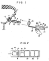
- Figure 1 is a schematic drawing of the overall tire inspection device of this invention
- Figure 2 is a block diagram showing the composition of the electric circuit of the said device of this invention
- Figure 3 to Figure 5 are electrical performance views of the said device of this invention
- Figure 6 is a cross-sectional view showing an example of the tire valve utilized for this invention
- Figure 7 is a cross-sectional view of the cap
- Figure 8 is a block diagram of a composition example of the said device using the tire valve shown in Figure 6
- Figure 9 is a perspective view of the main body of the said device
- Figure 10 is a cross-sectional view of other example of the tire valve utilized for this invention
- Figure 11 is a brief sectional view of another tire valve
- Figure 12 to Figure 20 are sectional views of tire valves showing examples of variety of shapes, formed portions, etc.
- Figure 21 is a sectional view of other example of the tire valve used for this invention
- Figure 22 is a sectional view of the cap
- Figure 23 is a block diagram of the said device
- Figure 24 is a sectional view of the valve core of the short type used for this invention
- Figure 25 is a sectional view of the axis utilized for the valve core shown in Figure 24.
- a tire 1 is fixed to a tire fixing rim 2, and a hole 3 for fitting a valve 4 is made on a slant of the rim 2.
- an O ring 6 is inserted inside the base end of the valve 4 of which cylindrical circumference is threaded so that the air does not leak from the above-mentioned hole3.
- the valve fixture 5, of which inside is threaded is inserted and screwed on so that the valve 4 is tightly fixed to the rim 2 in sealing up the air.
- a slender cylinder 7 housing the resonace part is screwed and fixed to the outer end of the valve 4.
- a cap 11 is screwed to the end of the cylinder 7 to prevent the intrurusion of mud, etc.
- the coil 8 is wound suitable times around the middle part of periphery of the cylinder 7, and pressure sensor 9, which turns on and off depending on the tire pressure volume, is fitted onto the hollow of inner wall of the cylinder 7, and is located near the coil 8.
- a rubber packing 12 acting as a valve in case of entry and escape of the air is attached to the end of the cylinder 7.
- the main body 20 is a slender rectangular parallelepiped which can be held in one hand 22, and a light 23 is mounted on the side slant of the front part so that one can, for example, clearly see the valve 4 and the like even in the dark. Also, furnished is a display 26 on the main body 20 so that when the tire internal pressure holds the proper value, a green lamp lights, and when it is less than the proper value, a red lamp lights in the said display.
- a detective rod 28 projects from the front part of the main body 20. And fitted to the front end of the detective rod 28 is a ring 29 with a round hole in the center, so the said ring 29 can be inserted to the outside of the resonance part 10. Also, an oscillating coil 30 is furnished in the ring 29 in the form of widing the above-mentioned hole, and is connected to an oscillator 24 housed in the main body 20, and the oscillator 24 is connected to a signal processing part 25. Furthermore, a battery 27 which is the power source of the above-mentioned light 23, the oscillator 24, etc, are housed in a casing 21 of the main body 20.
- the pressure sensor 9, a condenser 13 and a coil 8 are connected in parallel in a resonance part 10 set on the tire side. And, for example, the pressure sensor 9 turns on and off according to the volume of the tire pressure.
- a resistor 14 for adjusting the characteristic is arranged between the pressure sensor 9 and the condenser 13.
- the main body 20 of the tire inspetion device consists of such component parts as the oscillator 24 containing the oscillating coil 30 and the signal processing part 25 detecting the output of the oscillator 24 and performing the comparison, etc.
- the display 26 containing the green and red lamps lights up according to the output of the signal processing part 25 to inform the inspection results to one who conducts the inspection.
- the ring 29 of the main body 20 is, at first, inserted to the outside of the resonance part 10, which is fitted to the rim 2 of the automobile (not illustrated), with the power source switch of the main body 20 turned on.
- the pressure sensor 9 turns on, and the green lamp of the display 26 lights due to the function of electric circuit mentioned below.
- the pressure sensor 9 turns off, and the red lamp of the display 26 lights, indicating the pressure is below the proper value.
- Figure 3 shows the wave form of the oscillating current indicating the oscillating condition of the oscillator 24, while Figure 4 shows the condition that the oscillating current of the oscillator 24 changes with the approach to the resonance part 10 set on the wheel side.
- the wave forms shown with A in the said figure indicate the condition that the resonance part 10 and the oscillator 24 part with each other locationally and that the latter is not affected by the resonance part 10.
- the wave form shown with B indicates that, when the resonance part 10 approaches to the oscillating coil 30 of the oscillator 24, the electric current in the oscillator 24 becomes abnormal as the oscillating energy is absorbed into the resonance part 10, and, as a result, the amplitude of the oscillating current becomes almost zero.
- the signal processing part 25 detects and makes, as mentioned above, the comparison, etc. of the change in the output signal from the oscillator 24, and outputs the H level signal in proportion to the interval of width corresponding to B as shown in Figure 4, and makes the green lamp of the display 26 light in proportion to the interval of the H level shown in Figure 5.
- the inspection device can be simply composed by this invention, and the inspection method becomes quite easy.
- the tire inspection device of this invention makes the remodeling of automobiles, rims, etc. unnecessary as the oscillator, display, etc. are installed.
- the resonance part is only fitted to the tire valve, so the aforesaid environmental conditions are not severe, and the high reliability can be obtained.
- the number of oscillators and displays (that is, the main body of the tire inspection device) has been required as many as the member of tires of the automobiles, whereas this invention requires the minimum necessary number of main bodies of the inspection devices regardless of the number of tires. Needless to say, truck, bus and taxicab companies, etc. are required to control the tire internal pressure of their motor vehicles. In such cases, even if they possess a great many motor vehicles, if they employ the inspection devices of this invention, a very few main bodies of the said devices will meet the requirement, and they can carry out the collective control system of the tire pressure, etc. at a low expense.
- the checking by the said device of this invention can be easily done as the oscillating coil can be simply brought near the tips of the tire valves.
- the pressure sensor in the examples of this invention indicates whether the tire pressure holds the proper value or not by on-off action of the switch.
- other pressures sensors that the resistance value changes analogously according to the tire pressure volume as in the case of, for example, the variable resistor may be employed.
- the tire internal pressure may be indicated in detail in the display 26 of the said main body. For example, if a liquid crystal display means is used, the tire pressure condition can be seen more precisely.
- valve 4 of an optimum structure for measurement of the pressure and temperature in a tire will be described with reference to Fig. 6 and subsequent Figures.
- a valve stem 41 of the valve 4 made of a conductive material is formed from a first conductive member 41A and second conductive member 41B electrically isolated from each other by means of an insulative member 42 made of an insulator
- a sensor 43 for example, pressure sensor, is provided on the end of the valve stem 41 and connected at the one side thereof to the first conductive member 41A and at the other side to the second conductive member 41B.
- the cap 44 of the valve stem 41 incorporates an electronic circuit 45 of which a signal wire 46 is connected to the first conductive member 41A and the other signal wire 47 is connected to the second conductive member 41B.
- a signal from the sensor 43 can be received by the electronic circuit 45 through the first and second conductive members 41A and 41B as lead wire and processed for display.
- the detail of the cap 44 incorporating this electronic circuit 45 is shown in Figure 7.
- This cap 44 is also made of a conductive material.
- the base end of the first conductive member 41A insulated by the insulative member 42 is in contact with the signal wire 46 while the base end of the second conductive member 41B is in contact with the signal wire 47.
- the tire inspection system is built using the tire valve 4 shown in Figures 6 and and 7, it can be constructed, for example, as shown in Figures 8 and 9.
- the sensor 43 provided at the end of the valve stem 41 is connected to the electronic circuit 45 by means of the first and second conductive members 41A and 41B serving as lead wire, and the electronic circuit 45 is provided thereon with a capacitor 14 and coil 8, forming as a whole a resonator 10.
- the main body 20 of the inspection device comprises a cylinder 31, oscillating coil 30 provided in the cylinder 31, and an oscillator 24 to which the oscillating coil 30 is connected.
- the oscillator 24 is connected to a signal processor 25 which is connected to a display 26.
- a lamp 23 and a battery 27 feeding the oscillator 24, etc. are housed in a casing 21.
- the lamp 23 is provided to illuminate the valve 4 in a dark place or at night for easy setting the cylinder 31 on the valve 4.
- the display 26 lights blue when the detected tire internal pressure, etc. are appropriate, but it lights red if the detected values are inappropriate.
- the cylinder 31 is used in place of the ring 29 in Figure 1. Of course, however, the ring 29 may be used.
- Figure 10 shows an embodiment of the tire valve.
- the electronic circuit 45 is not incorporated in the cap 44, but in a member (such as nut or the like) fixed to the valve stem 41.
- the reference numeral 48A indicates a thread.
- Figure 11 shows another embodiment of the tire valve in which a combination of the sensor 43 and electronic circuit 45 is installed inside the tire 1, namely, to the rim 2 of the wheel and the signal wires 16 and 17 are connected to the first and second conductive materials 41A and 41B, respectively.
- Figures 12 thru 20 show other embodiments of the tire valve different in location of the insulative member 42 from one another.
- the insulative member 42 insu lating the first and second conductive members 41A and 41B from each other is not straight in the axial direction but so stepped at an intermediate point (indicated with I in Figure) that the first conductive member 11A is thinner at the free end side thereof (in the tire) than at the base side (at the cap side).
- the reference numeral 3 indicates a valve fixing nut (fixing member), 3A a valve washer and 18 an insulative packing provided between the rim 2 and the valve stem 41.
- the second conductive member 41B is fixed to the first conductive member 41A by calking the second conductive member 41B at the ends (indicated with II in Figure 13) of these conductive members 41A and 41B, and an insulative member 42 is formed along the calked portion. Because of this calking, the first and second conductive members 41A and 41B are prevented from being displaced in the axial direction.
- Figures 14 thru 19 show further embodiments different in location of the insulative member 42 or in shape of the valve body 1 from one another.
- the first and second conductive members 41A and 41B are made in a cylindrical form, respectively. As shown in Figure 20, however, the first and second conductive members 41A and 41B may be formed as semicircle in sectional shape so that they will form together a cylinder when attached to each other. The insulative member 42 may be placed as sandwiched between these conductive members.
- either of the contact and non-contact systems may be adopted.
- the tire valve in the inspection device has a valve stem made of a conductor composed of at least two conductive members, first and second, electrically isolated from each other by means of an insulative member made of an insulator for leading out as electric signals the pressure, temperature, etc. detected by the sensor or the like from inside the tire wheel through the first and second conductive members. Therefore, it it no necessary to specially work the wheel, and with either of the contact and non-contact systems to lead out such electric signals, the tire internal pressure or the like can be easily detected and a variety of inspection devices can be constructed at low costs.
- the valve stem 41 has a valve core 51 in it and is so designed as to be fixed to the rim 2 with a nut 3 (fixing member).
- the valve core 51 has a shaft 52 and a head 53 in which the shaft 52 is inserted and which is screwed in the inner circum ference of the valve stem 41.
- the valve core 51 has provided below the head 53 thereof a body 54 on the other circumference of which a body packing 55 is provided to assure a sealing between the body 54 and the inner circumference of the valve stem 41.
- the body 54 abuts at the lower end thereof a valve packing 57 provided around the shaft 52 and seated on a valve packing receiver 56.
- the head 53 is electrically connected to a spring holder 59 by means of the shaft 52 of the valve stem 41.
- the shaft 52 made of a conductor forms the first conductive member while the head 53 insulated from the first conductive member (shaft 52) by means of an insulative member 60, body 54, valve packing holder 56, spring 58, spring holder 59 and valve stem 41 form together the second conductive member.
- a sensor 43 of which an electrode wire 61 is kept in contact with the inner surface of the spring holder 59 by means of a spring 62.
- the reason why the spring 62 is used to keep the electrode wire 61 in contact with the inner surface of the spring holder 59 is that as the top 52A of the shaft 52 is pushed down, the electrode wire 61 also moves along the inner surface of the spring holder.
- the sensor 43 detects the internal pressure, temperature, etc. inside the tire and such pressure, temperature, etc. can be led out as electric signals through the first conductive member (shaft 52) and second conductive member (head 53, body 54, valve packing holder 56, spring 58 and spring holder 59).
- valve core 51 blocks the air in the tire when it is in the position shown in Figure 21, but when the top 52A of the shaft 52 is pushed down, the shaft 52 will push down the valve packing 57 and valve packing holder 56, whereby the sealing between the body 54 and valve packing 57 is released so that the air in the tire flows into the passage between the shaft 52 and body 54 and flows out through the clearance between the head 53 and shaft 52. Similarly, air can be injected into the tire.
- the lead wire 46 is provided with a clip 63 made of a conductive material, which gets in contact with the top 52A of the shaft 52 being the first conductive member. Since the top 52A is not coated with any insulative material, the signal on the shaft 52 being the first conductive member as lead wire from the sensor 43 can be sent to the electronic circuit 45 through the clip 63 and lead wire 46.
- the signal wire 47 permits the electronic circuit 45 to receive the signal sent from the sensor 43 through the valve stem 41. Therefore, in this embodiment, the valve stem 41 is also made of a conductive material to form a second conductive member.
- the electronic circuit 45 is provided in it with a capacitor 13 and coil 8 as in the embodiment shown in Figure 8, and forms as a whole an resonator 10.
- the main body 20 of the inspection device is constructed as in Figure 9.
- Figure 23 is a block diagram of the inspection device, similar to that shown in Figure 8.
- the electronic circuit 45 may not always be incorporated in the cap 44 but it may be provided in a member installed in the valve stem 41. Also, not that the elements of the first conductive member and those of the second conductive member are not limited to those in the embodiments shown in Figures. Appropriate parts can be selected with a consideration given to the electrical connection with the electronic circuit 45 and sensor 43.
- the first and second conductive members have only to be electrically isolated from each other by means of an insulative member 60. Further, the present invention cannot only be applied to the straight valve having been illustrated and described in the foregoing but also to any curved or bent valve. Further, the conductive members are not limited only to the first and second ones but a third, fourth and further conductive members can be constructed.
- Figures 24 and 25 show the valve core 51 and shaft 52 which are shorter.
- a spring 58 is incorporated in the body 54. Therefore, these embodiments needs any spring holder 59.
- the body 54 and valve packing holder 56 are not shown as connected but a projection or the like is provided which gets in contact with either the body or valve packing holder. The body and valve packing holder are put into contact with each other by the projection to serve as lead wire through which electrical signal is sent.
- either of the contact and non-contact systems may be adopted.
- the tire valve constructed as having been described in the foregoing is composed of the parts forming at least the first member and those forming the second conductive member, selected arbitrarily among the plural parts made of a conductor and forming the tire valve core and which are electrically isolated from one another by means of the insulative member made of an insulator to lead out as electric signals the sensor-detected pressure, temperature, etc. in the tire from the tire wheel inside through the first and second conductive members. Therefore, it is not necessary to specially work the wheel and it is easy to detect the pressure, etc. in the tire with either of the contact and non contact systems. Also a variety of inspection devices can be manufactured at low costs.
- the tire valve can be easily installed to either of the tube tire and tubeless tire.
- the tube valve can be manufactured without any high techniques. That is, in case the valve stem must be worked, a high technique is required since the durability of the valve stem must be maintained.
- the first and second conductive members consisting of the parts of the valve core have only to be electrically isolated from each other by means of an insulative member, the tire valve can be embodied at low costs. Also, the tire valve can be easily replaced similarly to the replacement of the ordinary valve core.
Landscapes
- Engineering & Computer Science (AREA)
- Mechanical Engineering (AREA)
- Measuring Fluid Pressure (AREA)
- Check Valves (AREA)
Abstract
Description
- The present invention relates to a tire inspection device quite suitable for checking the tire internal pressure and detecting the temperature in the tire, the strain of the tire wheel and the like.
- As the conventional mean of detecting, for example, the tire internal pressure (air pressure), known are device are devices a means of detection fitted on the tire side and having which utilizes the electromagnetic induction, electromagnetic resonance etc. to detect the tire internal pressure even while the automobile is running. They are of the so-called the non-contact system. Besides, other devices are known which transmit the tire internal pressure through the slip ring, ejection rod or the like. They are of the so-called contact system. The tire internal pressure detections of the non-contact system among them are complicated, and so need high manufacturing costs. Further, the wheels especially made for this system, the modification, etc. of automobiles are required as well. Furthermore, the maintenance of their reliability and environmental durability is difficult. And, what is more, the cost increase is obliged to solve these problems.
- In addition, the display-type tire internal pressure detections have hitherto been developed as a low-cost means. However, when they break down, the tire internal pressure is released to the air due to their original construction.
- And the detective operation is apt to occur under the low temperature during the winter season due to freezing. Therefore, they have problems in reliability and safety, so they have not yet attained the stage of the practical use.
- Moreover, of any tire internal pressure detections, the tire valves are merely manufactured for the purpose of filing the tire with air and maintaining the airtightness, and have not the structure meeting the purpose of detecting the pressure and temperature in the tire.
- As described above, various tire pressure internal detections have been developed. However, no contrivance has been made to the tire valves employed for them. Above all, no fully satisfactory tire pressure detections have been developed yet to date.
- This invention aims at providing the tire inspection device quite suitable for the detection of the tire internal pressure and temperature in the tire, the strain of the wheel and the like.
- In order to achieve the above-mentioned object, this invention consists roughly of the two units: one unit, which is fitted to the valve fixed to a tire fixing rim, is composed of the sensor of which output changes depending on the tire internal pressure and the temperature in the tire, etc.; and the resonance part containing a condenser and a resonance coil which resonates to the radiant electromagnetic waves reaching from outside. The other unit, which is the portable main body of the said tire inspection device, is composed of the oscillator, which generates the above-mentioned radiant electromagnetic waves; the oscillating coil projected from the said main body; the signal processing part which detects and processes the change of oscillating conditions produced in the said oscillator caused by resonance condition in the above-mentioned resonance part which changes according to the afore-mentioned tire internal pressure, temperature, etc.; and the display displaying the processed result to the outside.
- This invention makes it possible that: when the oscillating coil projected from the portable main body of the inspection device is brought near the resonance part fitted to the valve fixed to the rim, the resonance cindition changes according to the value detected by the sensor in the resonance part. Then, the change of the resonance condition is detected, and after signal processing, it is displayed in the display.
- Figure 1 is a schematic drawing of the overall tire inspection device of this invention; Figure 2 is a block diagram showing the composition of the electric circuit of the said device of this invention; Figure 3 to Figure 5 are electrical performance views of the said device of this invention; Figure 6 is a cross-sectional view showing an example of the tire valve utilized for this invention; Figure 7 is a cross-sectional view of the cap; Figure 8 is a block diagram of a composition example of the said device using the tire valve shown in Figure 6; Figure 9 is a perspective view of the main body of the said device; Figure 10 is a cross-sectional view of other example of the tire valve utilized for this invention; Figure 11 is a brief sectional view of another tire valve; Figure 12 to Figure 20 are sectional views of tire valves showing examples of variety of shapes, formed portions, etc. of the first and second electric conductors as well as the insulted parts: Figure 21 is a sectional view of other example of the tire valve used for this invention; Figure 22 is a sectional view of the cap; Figure 23 is a block diagram of the said device; Figure 24 is a sectional view of the valve core of the short type used for this invention; and Figure 25 is a sectional view of the axis utilized for the valve core shown in Figure 24.
- In the following, the tire inspection device of this invention will be exaplained on the basis of illustrated embodiments:
- In Figure 1, a tire 1 is fixed to a
tire fixing rim 2, and ahole 3 for fitting avalve 4 is made on a slant of therim 2. In order to seal up the gap, an O ring 6 is inserted inside the base end of thevalve 4 of which cylindrical circumference is threaded so that the air does not leak from the above-mentioned hole3. From the side around the outer end of thevalve 4, the valve fixture 5, of which inside is threaded, is inserted and screwed on so that thevalve 4 is tightly fixed to therim 2 in sealing up the air. Aslender cylinder 7 housing the resonace part is screwed and fixed to the outer end of thevalve 4. And acap 11 is screwed to the end of thecylinder 7 to prevent the intrurusion of mud, etc. - The
coil 8 is wound suitable times around the middle part of periphery of thecylinder 7, and pressure sensor 9, which turns on and off depending on the tire pressure volume, is fitted onto the hollow of inner wall of thecylinder 7, and is located near thecoil 8. - In addition, a
rubber packing 12 acting as a valve in case of entry and escape of the air is attached to the end of thecylinder 7. - In the following, the composition of a
main body 20 of the tire inspection device of this invention will be described: - As shown in Figure 1, the
main body 20 is a slender rectangular parallelepiped which can be held in onehand 22, and alight 23 is mounted on the side slant of the front part so that one can, for example, clearly see thevalve 4 and the like even in the dark. Also, furnished is adisplay 26 on themain body 20 so that when the tire internal pressure holds the proper value, a green lamp lights, and when it is less than the proper value, a red lamp lights in the said display. - Moreover, a
detective rod 28 projects from the front part of themain body 20. And fitted to the front end of thedetective rod 28 is aring 29 with a round hole in the center, so the saidring 29 can be inserted to the outside of theresonance part 10. Also, anoscillating coil 30 is furnished in thering 29 in the form of widing the above-mentioned hole, and is connected to anoscillator 24 housed in themain body 20, and theoscillator 24 is connected to asignal processing part 25. Furthermore, abattery 27 which is the power source of the above-mentionedlight 23, theoscillator 24, etc, are housed in acasing 21 of themain body 20. - The block composition of the electric circuit of the tire inspection device of this invention will be described with Figure 2 in the following:
- The pressure sensor 9, a
condenser 13 and acoil 8 are connected in parallel in aresonance part 10 set on the tire side. And, for example, the pressure sensor 9 turns on and off according to the volume of the tire pressure. In addition, aresistor 14 for adjusting the characteristic is arranged between the pressure sensor 9 and thecondenser 13. - On the other hand, the
main body 20 of the tire inspetion device consists of such component parts as theoscillator 24 containing theoscillating coil 30 and thesignal processing part 25 detecting the output of theoscillator 24 and performing the comparison, etc. - In addition, the
display 26 containing the green and red lamps lights up according to the output of thesignal processing part 25 to inform the inspection results to one who conducts the inspection. - In the following, how to use the tire inspection device of this invention will be described:
- As shown in Figure 1, the
ring 29 of themain body 20 is, at first, inserted to the outside of theresonance part 10, which is fitted to therim 2 of the automobile (not illustrated), with the power source switch of themain body 20 turned on. - Thereupon, in case the tire internal pressure holds, for example, the proper value, the pressure sensor 9 turns on, and the green lamp of the
display 26 lights due to the function of electric circuit mentioned below. - Contrarily, in case the tire pressure is lower than the proper valve, the pressure sensor 9 turns off, and the red lamp of the
display 26 lights, indicating the pressure is below the proper value. - In the following, the performance of electric circuit of the tire inspection device of this invention will be explained with Figure 3 to Figure 5:
- Figure 3 shows the wave form of the oscillating current indicating the oscillating condition of the
oscillator 24, while Figure 4 shows the condition that the oscillating current of theoscillator 24 changes with the approach to theresonance part 10 set on the wheel side. The wave forms shown with A in the said figure indicate the condition that theresonance part 10 and theoscillator 24 part with each other locationally and that the latter is not affected by theresonance part 10. Also, the wave form shown with B indicates that, when theresonance part 10 approaches to theoscillating coil 30 of theoscillator 24, the electric current in theoscillator 24 becomes abnormal as the oscillating energy is absorbed into theresonance part 10, and, as a result, the amplitude of the oscillating current becomes almost zero. - The signal processing
part 25 detects and makes, as mentioned above, the comparison, etc. of the change in the output signal from theoscillator 24, and outputs the H level signal in proportion to the interval of width corresponding to B as shown in Figure 4, and makes the green lamp of thedisplay 26 light in proportion to the interval of the H level shown in Figure 5. - On the contrary, in case the tire pressure is lower than the proper value when the
ring 29 of themain body 20 is inserted to the outside of theresonance part 10, the pressure sensor 9 (see Figure 2) remains in "off" condition, so theresonance part 10 does not form the closed loop. Accordingly, when thering 29 of themain body 20 approaches to theresonance part 10, the output of theoscillator 24 remains as shown in Figure 3. Therefore, the H level signal as indicated in Figure 5 does not occur. In such a case, the red lamp of thedisplay 26 lights, and warning is given to inform that the tire internal pressure is below the proper value. - As described above, the inspection device can be simply composed by this invention, and the inspection method becomes quite easy. In addition, the tire inspection device of this invention makes the remodeling of automobiles, rims, etc. unnecessary as the oscillator, display, etc. are installed. Besides, the resonance part is only fitted to the tire valve, so the aforesaid environmental conditions are not severe, and the high reliability can be obtained.
- Hitherto, the number of oscillators and displays (that is, the main body of the tire inspection device) has been required as many as the member of tires of the automobiles, whereas this invention requires the minimum necessary number of main bodies of the inspection devices regardless of the number of tires. Needless to say, truck, bus and taxicab companies, etc. are required to control the tire internal pressure of their motor vehicles. In such cases, even if they possess a great many motor vehicles, if they employ the inspection devices of this invention, a very few main bodies of the said devices will meet the requirement, and they can carry out the collective control system of the tire pressure, etc. at a low expense.
- Although these companies are required to make some adjustment to maintain the accuracy of the displays of the main bodies of the said devices, thanks to a small number of the main bodies, they can reduce the cost required for the adjustment.
- In general, concerning the vehicles particularly driven on muddy roads, in a cold district, etc., surroundings of the valves are likely to become very dirty with mud, etc. or to be adhered with mud. Even in case that mud and the like freeze to the surroundings in the winter season, as long as the tire inspection device of this invention is utilized, the inspection can be conducted with ease, because the removal of the valves, etc. are not required.
- In case of checking inner tires of dual wheels of large automobiles such as buses, the checking by the said device of this invention can be easily done as the oscillating coil can be simply brought near the tips of the tire valves.
- The pressure sensor in the examples of this invention indicates whether the tire pressure holds the proper value or not by on-off action of the switch. However, other pressures sensors that the resistance value changes analogously according to the tire pressure volume as in the case of, for example, the variable resistor may be employed. In this case, the tire internal pressure may be indicated in detail in the
display 26 of the said main body. For example, if a liquid crystal display means is used, the tire pressure condition can be seen more precisely. - Next, the
valve 4 of an optimum structure for measurement of the pressure and temperature in a tire will be described with reference to Fig. 6 and subsequent Figures. - Referring now to Figure 6, a
valve stem 41 of thevalve 4 made of a conductive material (usually, brass) is formed from a firstconductive member 41A and secondconductive member 41B electrically isolated from each other by means of aninsulative member 42 made of aninsulator A sensor 43, for example, pressure sensor, is provided on the end of thevalve stem 41 and connected at the one side thereof to the firstconductive member 41A and at the other side to the secondconductive member 41B. In the embodiment shown in Fig. 6, thecap 44 of thevalve stem 41 incorporates anelectronic circuit 45 of which asignal wire 46 is connected to the firstconductive member 41A and theother signal wire 47 is connected to the secondconductive member 41B. Thus, when thecap 44 is attached to thevalve stem 41, a signal from thesensor 43 can be received by theelectronic circuit 45 through the first and secondconductive members cap 44 incorporating thiselectronic circuit 45 is shown in Figure 7. Thiscap 44 is also made of a conductive material. The base end of the firstconductive member 41A insulated by the insulativemember 42 is in contact with thesignal wire 46 while the base end of the secondconductive member 41B is in contact with thesignal wire 47. In case the tire inspection system is built using thetire valve 4 shown in Figures 6 and and 7, it can be constructed, for example, as shown in Figures 8 and 9. That is, thesensor 43 provided at the end of thevalve stem 41 is connected to theelectronic circuit 45 by means of the first and secondconductive members electronic circuit 45 is provided thereon with acapacitor 14 andcoil 8, forming as a whole aresonator 10. Themain body 20 of the inspection device comprises acylinder 31, oscillatingcoil 30 provided in thecylinder 31, and anoscillator 24 to which the oscillatingcoil 30 is connected. Theoscillator 24 is connected to asignal processor 25 which is connected to adisplay 26. Alamp 23 and abattery 27 feeding theoscillator 24, etc. are housed in acasing 21. Thelamp 23 is provided to illuminate thevalve 4 in a dark place or at night for easy setting thecylinder 31 on thevalve 4. Thedisplay 26 lights blue when the detected tire internal pressure, etc. are appropriate, but it lights red if the detected values are inappropriate. In the embodiment shown in Figure 9, thecylinder 31 is used in place of thering 29 in Figure 1. Of course, however, thering 29 may be used. - Figure 10 shows an embodiment of the tire valve. In this embodiment, the
electronic circuit 45 is not incorporated in thecap 44, but in a member (such as nut or the like) fixed to thevalve stem 41. Thereference numeral 48A indicates a thread. - Figure 11 shows another embodiment of the tire valve in which a combination of the
sensor 43 andelectronic circuit 45 is installed inside the tire 1, namely, to therim 2 of the wheel and thesignal wires conductive materials - Figures 12 thru 20 show other embodiments of the tire valve different in location of the
insulative member 42 from one another. In Figure 12, the insulativemember 42 insu lating the first and secondconductive members conductive member 41A is pressed from the base side thereof, it will not be separated from the secondconductive member 41B. In Figure 12, thereference numeral 3 indicates a valve fixing nut (fixing member), 3A a valve washer and 18 an insulative packing provided between therim 2 and thevalve stem 41. In the embodiment shown in Figure 13, the secondconductive member 41B is fixed to the firstconductive member 41A by calking the secondconductive member 41B at the ends (indicated with II in Figure 13) of theseconductive members insulative member 42 is formed along the calked portion. Because of this calking, the first and secondconductive members insulative member 42 or in shape of the valve body 1 from one another. - In any of the aforementioned embodiments, the first and second
conductive members conductive members member 42 may be placed as sandwiched between these conductive members. - For leading out electric signals the pressure, temperature, etc. detected by the
sensor 43 or the like from inside the tire wheel through the first and secondconductive members - As having been described in the foregoing, the tire valve in the inspection device has a valve stem made of a conductor composed of at least two conductive members, first and second, electrically isolated from each other by means of an insulative member made of an insulator for leading out as electric signals the pressure, temperature, etc. detected by the sensor or the like from inside the tire wheel through the first and second conductive members. Therefore, it it no necessary to specially work the wheel, and with either of the contact and non-contact systems to lead out such electric signals, the tire internal pressure or the like can be easily detected and a variety of inspection devices can be constructed at low costs.
- Regarding the
valve 24 shown in Figure 21, thevalve stem 41 has avalve core 51 in it and is so designed as to be fixed to therim 2 with a nut 3 (fixing member). Thevalve core 51 has ashaft 52 and ahead 53 in which theshaft 52 is inserted and which is screwed in the inner circum ference of thevalve stem 41. Thevalve core 51 has provided below thehead 53 thereof abody 54 on the other circumference of which a body packing 55 is provided to assure a sealing between thebody 54 and the inner circumference of thevalve stem 41. Thebody 54 abuts at the lower end thereof a valve packing 57 provided around theshaft 52 and seated on avalve packing receiver 56. Thehead 53 is electrically connected to aspring holder 59 by means of theshaft 52 of thevalve stem 41. Thus, theshaft 52 made of a conductor forms the first conductive member while thehead 53 insulated from the first conductive member (shaft 52) by means of aninsulative member 60,body 54,valve packing holder 56,spring 58,spring holder 59 and valve stem 41 form together the second conductive member. There is provided at the end of the shaft 52 asensor 43 of which anelectrode wire 61 is kept in contact with the inner surface of thespring holder 59 by means of aspring 62. The reason why thespring 62 is used to keep theelectrode wire 61 in contact with the inner surface of thespring holder 59 is that as the top 52A of theshaft 52 is pushed down, theelectrode wire 61 also moves along the inner surface of the spring holder. Thesensor 43 detects the internal pressure, temperature, etc. inside the tire and such pressure, temperature, etc. can be led out as electric signals through the first conductive member (shaft 52) and second conductive member (head 53,body 54,valve packing holder 56,spring 58 and spring holder 59). Thevalve core 51 blocks the air in the tire when it is in the position shown in Figure 21, but when the top 52A of theshaft 52 is pushed down, theshaft 52 will push down the valve packing 57 andvalve packing holder 56, whereby the sealing between thebody 54 and valve packing 57 is released so that the air in the tire flows into the passage between theshaft 52 andbody 54 and flows out through the clearance between thehead 53 andshaft 52. Similarly, air can be injected into the tire. - An example of the process after the information detected by
such sensor 43 is led out as electric signal through the first and second conductive members will be described with reference to Figure 22. The inspection of the tire internal pressure by the device according to the present invention will be explained under the assumption that thesensor 43 is a pressure sensor. Theelectronic circuit 45 is incorporated in thecap 44 screwed in thevalve stem 41 and thesignal wires electronic circuit 45 are connected to the first and second conductive members, respectively. Thus, when thecap 44 is attached to thevalve stem 41, a signal from thesensor 43 can be sent to theelectronic circuit 45 through the first and second conductive members serving as lead wires, and the signal can be processed for display. Thelead wire 46 is provided with aclip 63 made of a conductive material, which gets in contact with the top 52A of theshaft 52 being the first conductive member. Since the top 52A is not coated with any insulative material, the signal on theshaft 52 being the first conductive member as lead wire from thesensor 43 can be sent to theelectronic circuit 45 through theclip 63 andlead wire 46. Thesignal wire 47 permits theelectronic circuit 45 to receive the signal sent from thesensor 43 through thevalve stem 41. Therefore, in this embodiment, thevalve stem 41 is also made of a conductive material to form a second conductive member. Theelectronic circuit 45 is provided in it with acapacitor 13 andcoil 8 as in the embodiment shown in Figure 8, and forms as a whole anresonator 10. Themain body 20 of the inspection device is constructed as in Figure 9. Figure 23 is a block diagram of the inspection device, similar to that shown in Figure 8. - It should be noted that the
electronic circuit 45 may not always be incorporated in thecap 44 but it may be provided in a member installed in thevalve stem 41. Also, not that the elements of the first conductive member and those of the second conductive member are not limited to those in the embodiments shown in Figures. Appropriate parts can be selected with a consideration given to the electrical connection with theelectronic circuit 45 andsensor 43. The first and second conductive members have only to be electrically isolated from each other by means of aninsulative member 60. Further, the present invention cannot only be applied to the straight valve having been illustrated and described in the foregoing but also to any curved or bent valve. Further, the conductive members are not limited only to the first and second ones but a third, fourth and further conductive members can be constructed. - Figures 24 and 25 show the
valve core 51 andshaft 52 which are shorter. According to these embodiments, aspring 58 is incorporated in thebody 54. Therefore, these embodiments needs anyspring holder 59. Also in these embodiments, thebody 54 andvalve packing holder 56 are not shown as connected but a projection or the like is provided which gets in contact with either the body or valve packing holder. The body and valve packing holder are put into contact with each other by the projection to serve as lead wire through which electrical signal is sent. - For leading out as electric signal the pressure, temperature, etc. in the tire, detected by the
sensor 43 or the like, from the inside the tire wheel through the first and second conductive members by using thesensor 43 or the like, either of the contact and non-contact systems may be adopted. - The tire valve constructed as having been described in the foregoing is composed of the parts forming at least the first member and those forming the second conductive member, selected arbitrarily among the plural parts made of a conductor and forming the tire valve core and which are electrically isolated from one another by means of the insulative member made of an insulator to lead out as electric signals the sensor-detected pressure, temperature, etc. in the tire from the tire wheel inside through the first and second conductive members. Therefore, it is not necessary to specially work the wheel and it is easy to detect the pressure, etc. in the tire with either of the contact and non contact systems. Also a variety of inspection devices can be manufactured at low costs. The tire valve can be easily installed to either of the tube tire and tubeless tire. Further, the tube valve can be manufactured without any high techniques. That is, in case the valve stem must be worked, a high technique is required since the durability of the valve stem must be maintained. However, since the first and second conductive members consisting of the parts of the valve core have only to be electrically isolated from each other by means of an insulative member, the tire valve can be embodied at low costs. Also, the tire valve can be easily replaced similarly to the replacement of the ordinary valve core.
Claims (4)
a resonator including a sensor attached to a valve fixed in a tire fixing rim and of which the output varies depending upon the tire internal pressure and the temperature in the tire etc. coil which resonates with an external radiation electromagnetic wave and a capacitor;
a main body including a signal processor having an oscillator of which the oscillation coil generating said radiation electromagnetic wave is attached as projected from the main body and which detects and processes any change in oscillation state in said oscillation which has been caused by the resonance state of said resonator which varies depending upon the pressure, temperature, etc in said tire, and a display which shows the result of the processing.
Applications Claiming Priority (6)
| Application Number | Priority Date | Filing Date | Title |
|---|---|---|---|
| JP62184542A JP2623480B2 (en) | 1987-07-23 | 1987-07-23 | Tire pressure checking device |
| JP184542/87 | 1987-07-23 | ||
| JP317165/87 | 1987-12-15 | ||
| JP62317165A JP2724831B2 (en) | 1987-12-15 | 1987-12-15 | Tire valve |
| JP62326415A JP2654621B2 (en) | 1987-12-23 | 1987-12-23 | Tire valve core |
| JP326415/87 | 1987-12-23 |
Publications (2)
| Publication Number | Publication Date |
|---|---|
| EP0301443A1 true EP0301443A1 (en) | 1989-02-01 |
| EP0301443B1 EP0301443B1 (en) | 1993-09-29 |
Family
ID=27325442
Family Applications (1)
| Application Number | Title | Priority Date | Filing Date |
|---|---|---|---|
| EP88111882A Expired - Lifetime EP0301443B1 (en) | 1987-07-23 | 1988-07-23 | Tire inspection device |
Country Status (3)
| Country | Link |
|---|---|
| US (1) | US4918423A (en) |
| EP (1) | EP0301443B1 (en) |
| DE (1) | DE3884506T2 (en) |
Cited By (15)
| Publication number | Priority date | Publication date | Assignee | Title |
|---|---|---|---|---|
| DE3931830A1 (en) * | 1988-09-26 | 1990-03-29 | Bridgestone Corp | TIRE VALVE |
| DE4133999A1 (en) * | 1991-10-14 | 1993-04-22 | Rainer Achterholt | Motor vehicle pneumatic tyre pressure measuring and indicating appts. - contains valve with pressure sensor, wireless signal transmitter, activation unit with receiver, remote controller with pressure signal receiver, activation signal transmitter, and display |
| DE4133991A1 (en) * | 1991-10-14 | 1993-04-22 | Rainer Achterholt | Tyre pressure measuring and indicating appts. - has remote control actuator with activating signal transmitter, with receiver in tyre valve cap |
| DE4133993A1 (en) * | 1991-10-14 | 1993-04-22 | Rainer Achterholt | Motor vehicle pneumatic tyres pressure measuring and indicating - containing valve with pressure sensor, wireless signal transmitter, activation unit with receiver, remote controller with pressure signal receiver, activation signal transmitter, display |
| ES2068053A2 (en) * | 1991-07-17 | 1995-04-01 | Bozal Carlos Felipe Cobos | Remote device for pressure measurement of a vehicle's tyres |
| WO1997000785A1 (en) * | 1995-06-23 | 1997-01-09 | Widner Ronald D | Miniature combination valve and pressure transducer and system |
| WO1997009187A1 (en) * | 1995-09-01 | 1997-03-13 | Fast Air, S.L. | Method and system for measuring and adjusting pressure of tyres |
| EP0807026A4 (en) * | 1995-02-23 | 1998-04-29 | Nicholas Mangafas | ANSWERING MOUNTED ON A TIRE VALVE IN A PRESSURE REMOTE CONTROL DEVICE |
| US6148888A (en) * | 1995-09-01 | 2000-11-21 | Fast Air, S.L. | Method and system for measuring and adjusting pressure of tires |
| EP1816014A2 (en) | 2006-02-06 | 2007-08-08 | Pacific Industrial Co., Ltd. | Tire pressure detecting device and tire monitor system |
| WO2010053515A1 (en) * | 2008-10-29 | 2010-05-14 | Schrader Electronics Ltd. | Tire pressure sensing devices, systems and methods employing an acoustic amplifier |
| WO2010149902A1 (en) * | 2009-06-26 | 2010-12-29 | Schrader Sas | Valve integrating a sensor |
| EP2604450A4 (en) * | 2010-08-09 | 2014-01-01 | Bridgestone Corp | Tire internal pressure measuring system |
| EP3056362A1 (en) * | 2015-02-12 | 2016-08-17 | MAN Truck & Bus AG | Device and method for supporting a driver of a vehicle, in particular a commercial vehicle |
| GB2575822A (en) * | 2018-07-24 | 2020-01-29 | Itireair Ltd | Tyre pressure sensor module positioning with respect to a mobile elctronic device |
Families Citing this family (26)
| Publication number | Priority date | Publication date | Assignee | Title |
|---|---|---|---|---|
| DE3818207A1 (en) * | 1988-05-28 | 1989-11-30 | Bosch Gmbh Robert | TIRE PRESSURE AND TEMPERATURE SENSOR |
| USD331371S (en) | 1990-09-12 | 1992-12-01 | Weng Hsi K | Multi-purpose tire pressure gauge |
| WO1993008036A1 (en) * | 1991-10-14 | 1993-04-29 | Rainer Achterholt | Process, device and valve cap for measuring and displaying tire pressure |
| WO1993008035A1 (en) * | 1991-10-14 | 1993-04-29 | Rainer Achterholt | Process, device and valve for measuring and displaying tire pressure |
| GB2263774B (en) * | 1992-01-23 | 1995-04-12 | Huang Tien Tsai | Tire pressure indicator |
| GB9203693D0 (en) * | 1992-02-20 | 1992-04-08 | Westland Aerostructures Ltd | Pressure measurement systems |
| US5537090A (en) * | 1995-01-20 | 1996-07-16 | Thomas; Stephen E. | Truck tire underinflation detection and control system |
| US5731516A (en) * | 1995-06-07 | 1998-03-24 | Handfield; Michael | System and method for monitoring a pneumatic tire |
| USH1744H (en) * | 1995-09-21 | 1998-08-04 | Clayton; Stanley R. | Wireless remote sensing thermometer |
| US5844130A (en) * | 1996-04-03 | 1998-12-01 | Ssi Technologies | Apparatus for maintaining a constant radial distance between a transmitting circuit and an antenna coil |
| US5874680A (en) * | 1996-08-12 | 1999-02-23 | Moore; Randy A. | Combination in-line pressure sensor and portable gauge head |
| US6812824B1 (en) | 1996-10-17 | 2004-11-02 | Rf Technologies, Inc. | Method and apparatus combining a tracking system and a wireless communication system |
| KR20000049066A (en) * | 1996-10-17 | 2000-07-25 | 핀포인트 코포레이션 | Article tracking system |
| US6025725A (en) * | 1996-12-05 | 2000-02-15 | Massachusetts Institute Of Technology | Electrically active resonant structures for wireless monitoring and control |
| US6710708B2 (en) * | 1999-02-05 | 2004-03-23 | Schrader-Bridgeport International, Inc. | Method and apparatus for a remote tire pressure monitoring system |
| US6629454B2 (en) * | 2000-11-21 | 2003-10-07 | Lundqvist Torbjoern Boson | Tire pressure monitoring device |
| US6438467B1 (en) | 2001-01-02 | 2002-08-20 | Trw Inc. | Remote control convenience and information conveyance system associated with a vehicle |
| US20020189336A1 (en) * | 2001-06-15 | 2002-12-19 | Mcewan Technologies, Llc | Radar monitoring system for tires and wheels |
| DE10152340B4 (en) | 2001-10-24 | 2004-11-18 | Siemens Ag | System and method for monitoring the wheels of a motor vehicle |
| US20040112129A1 (en) * | 2002-02-20 | 2004-06-17 | Lundqvist Torbjorn Boson | Tire pressure monitoring devices |
| US7072163B2 (en) * | 2004-10-19 | 2006-07-04 | Mccollough Jr Norman D | Method and apparatus for a remote electric power line conductor faulted circuit current monitoring system |
| US7187275B2 (en) * | 2004-10-21 | 2007-03-06 | Mccollough Jr Norman D | Method and apparatus for a remote electric power line conductor faulted circuit current, conductor temperature, conductor potential and conductor strain monitoring and alarm system |
| US20060116602A1 (en) * | 2004-12-01 | 2006-06-01 | Alden Dana A | Medical sensing device and system |
| US7336164B2 (en) * | 2006-02-23 | 2008-02-26 | Dymos Co., Ltd. | Tire pressure monitoring system and sensor therefor |
| GB0724536D0 (en) | 2007-12-17 | 2008-01-30 | Opus Project Man Ltd | Measuring Tyre pressure |
| US11865872B2 (en) | 2020-11-02 | 2024-01-09 | Tdk Corporation | Interconnects for electrical components positioned adjacent to vehicle tires |
Citations (5)
| Publication number | Priority date | Publication date | Assignee | Title |
|---|---|---|---|---|
| DE2260522A1 (en) * | 1971-12-11 | 1973-06-14 | Lucas Electrical Co Ltd | PRESSURE PROBE |
| DE2824992A1 (en) * | 1978-06-07 | 1979-12-13 | Bridgestone Tire Co Ltd | Automatic warning system for tyre pressure - includes resonant circuit on tyre valve and tuned detector circuit on chassis |
| EP0042790A1 (en) * | 1980-06-19 | 1981-12-30 | Societe Anonyme De Telecommunications (S.A.T.) | Tyre-pressure measuring device, especially for airplanes |
| AT381477B (en) * | 1979-12-19 | 1986-10-27 | Bosch Gmbh Robert | DEVICE FOR MONITORING THE AIR PRESSURE IN THE TIRE OF A VEHICLE WHEEL |
| WO1987004123A1 (en) * | 1986-01-08 | 1987-07-16 | Robert Bosch Gmbh | Circuit for transmitting values measured at vehicle wheels |
Family Cites Families (3)
| Publication number | Priority date | Publication date | Assignee | Title |
|---|---|---|---|---|
| US4074227A (en) * | 1974-11-15 | 1978-02-14 | Kalmus Henry P | Tire pressure indicator |
| US4308520A (en) * | 1976-07-30 | 1981-12-29 | Edcliff Instruments | Tire pressure indicator |
| US4704901A (en) * | 1986-05-19 | 1987-11-10 | Neotech Industries, Inc. | Tire pressure gauge |
-
1988
- 1988-07-23 EP EP88111882A patent/EP0301443B1/en not_active Expired - Lifetime
- 1988-07-23 DE DE88111882T patent/DE3884506T2/en not_active Expired - Fee Related
- 1988-07-25 US US07/223,493 patent/US4918423A/en not_active Expired - Lifetime
Patent Citations (5)
| Publication number | Priority date | Publication date | Assignee | Title |
|---|---|---|---|---|
| DE2260522A1 (en) * | 1971-12-11 | 1973-06-14 | Lucas Electrical Co Ltd | PRESSURE PROBE |
| DE2824992A1 (en) * | 1978-06-07 | 1979-12-13 | Bridgestone Tire Co Ltd | Automatic warning system for tyre pressure - includes resonant circuit on tyre valve and tuned detector circuit on chassis |
| AT381477B (en) * | 1979-12-19 | 1986-10-27 | Bosch Gmbh Robert | DEVICE FOR MONITORING THE AIR PRESSURE IN THE TIRE OF A VEHICLE WHEEL |
| EP0042790A1 (en) * | 1980-06-19 | 1981-12-30 | Societe Anonyme De Telecommunications (S.A.T.) | Tyre-pressure measuring device, especially for airplanes |
| WO1987004123A1 (en) * | 1986-01-08 | 1987-07-16 | Robert Bosch Gmbh | Circuit for transmitting values measured at vehicle wheels |
Cited By (27)
| Publication number | Priority date | Publication date | Assignee | Title |
|---|---|---|---|---|
| DE3931830A1 (en) * | 1988-09-26 | 1990-03-29 | Bridgestone Corp | TIRE VALVE |
| DE3931830C2 (en) * | 1988-09-26 | 1999-01-28 | Bridgestone Corp | Tire valve |
| ES2068053A2 (en) * | 1991-07-17 | 1995-04-01 | Bozal Carlos Felipe Cobos | Remote device for pressure measurement of a vehicle's tyres |
| DE4133999A1 (en) * | 1991-10-14 | 1993-04-22 | Rainer Achterholt | Motor vehicle pneumatic tyre pressure measuring and indicating appts. - contains valve with pressure sensor, wireless signal transmitter, activation unit with receiver, remote controller with pressure signal receiver, activation signal transmitter, and display |
| DE4133991A1 (en) * | 1991-10-14 | 1993-04-22 | Rainer Achterholt | Tyre pressure measuring and indicating appts. - has remote control actuator with activating signal transmitter, with receiver in tyre valve cap |
| DE4133993A1 (en) * | 1991-10-14 | 1993-04-22 | Rainer Achterholt | Motor vehicle pneumatic tyres pressure measuring and indicating - containing valve with pressure sensor, wireless signal transmitter, activation unit with receiver, remote controller with pressure signal receiver, activation signal transmitter, display |
| EP0807026A4 (en) * | 1995-02-23 | 1998-04-29 | Nicholas Mangafas | ANSWERING MOUNTED ON A TIRE VALVE IN A PRESSURE REMOTE CONTROL DEVICE |
| WO1997000785A1 (en) * | 1995-06-23 | 1997-01-09 | Widner Ronald D | Miniature combination valve and pressure transducer and system |
| WO1997009187A1 (en) * | 1995-09-01 | 1997-03-13 | Fast Air, S.L. | Method and system for measuring and adjusting pressure of tyres |
| US6148888A (en) * | 1995-09-01 | 2000-11-21 | Fast Air, S.L. | Method and system for measuring and adjusting pressure of tires |
| EP1816014A2 (en) | 2006-02-06 | 2007-08-08 | Pacific Industrial Co., Ltd. | Tire pressure detecting device and tire monitor system |
| EP1816014A3 (en) * | 2006-02-06 | 2009-06-17 | Pacific Industrial Co., Ltd. | Tire pressure detecting device and tire monitor system |
| WO2010053515A1 (en) * | 2008-10-29 | 2010-05-14 | Schrader Electronics Ltd. | Tire pressure sensing devices, systems and methods employing an acoustic amplifier |
| US8072321B2 (en) | 2008-10-29 | 2011-12-06 | Schrader Electronics. Ltd. | Tire pressure sensing devices, systems and methods employing an acoustic amplifier |
| WO2010149902A1 (en) * | 2009-06-26 | 2010-12-29 | Schrader Sas | Valve integrating a sensor |
| FR2947321A1 (en) * | 2009-06-26 | 2010-12-31 | Schrader Sas | VALVE INTEGRATING A SENSOR |
| EP2604450A4 (en) * | 2010-08-09 | 2014-01-01 | Bridgestone Corp | Tire internal pressure measuring system |
| US8910513B2 (en) | 2010-08-09 | 2014-12-16 | Birdgestone Corporation | Tire inner pressure measurement system |
| CN105882332A (en) * | 2015-02-12 | 2016-08-24 | 曼卡车和巴士股份公司 | Method and device for assisting a driver of a vehicle, in particular a commercial vehicle |
| EP3056362A1 (en) * | 2015-02-12 | 2016-08-17 | MAN Truck & Bus AG | Device and method for supporting a driver of a vehicle, in particular a commercial vehicle |
| US9963003B2 (en) | 2015-02-12 | 2018-05-08 | Man Truck & Bus Ag | Method and device for assisting a driver of a vehicle, in particular a commercial vehicle |
| AU2016200658B2 (en) * | 2015-02-12 | 2019-11-28 | Man Truck & Bus Ag | Method and device for assisting a driver of a vehicle, in particular a commercial vehicle |
| CN105882332B (en) * | 2015-02-12 | 2021-03-12 | 曼卡车和巴士股份公司 | Method and device for assisting a driver of a vehicle, in particular a commercial vehicle |
| CN112776543A (en) * | 2015-02-12 | 2021-05-11 | 曼卡车和巴士股份公司 | Method and device for assisting a driver of a vehicle, in particular a commercial vehicle |
| EP4119365A1 (en) * | 2015-02-12 | 2023-01-18 | MAN Truck & Bus SE | Air valve for vehicle tyres |
| GB2575822A (en) * | 2018-07-24 | 2020-01-29 | Itireair Ltd | Tyre pressure sensor module positioning with respect to a mobile elctronic device |
| US11376900B2 (en) | 2018-07-24 | 2022-07-05 | Tizap Ltd | Vehicle wheel monitoring system |
Also Published As
| Publication number | Publication date |
|---|---|
| US4918423A (en) | 1990-04-17 |
| DE3884506T2 (en) | 1994-05-11 |
| EP0301443B1 (en) | 1993-09-29 |
| DE3884506D1 (en) | 1993-11-04 |
Similar Documents
| Publication | Publication Date | Title |
|---|---|---|
| EP0301443B1 (en) | Tire inspection device | |
| US4998092A (en) | Tire valve | |
| AU2002219805B2 (en) | Tire pressure monitoring device | |
| JP2756863B2 (en) | Valve cap for generating pressure drop signal | |
| US4458535A (en) | Drive defect detector | |
| US4180795A (en) | Alarm device for informing reduction of pneumatic pressure of tire | |
| US4334215A (en) | Continuous heat and pressure surveillance system for pneumatic tires | |
| US7271709B2 (en) | Robust method and system for the automatic detection of a detached remote tire pressure sensor of a tire pressure monitoring system | |
| AU2002219805A1 (en) | Tire pressure monitoring device | |
| GB2166598A (en) | Device for indicating abnormal pressure in a tyre on a vehicle in motion | |
| JP3982830B2 (en) | Remote tire pressure monitoring system | |
| US5531109A (en) | Indicator of the air pressure in the pneumatic tires of a vehicle based on a capacitive coupling | |
| US3715719A (en) | Tire pressure indication system | |
| US4196414A (en) | Integral tire inflation valve and tire height sensor | |
| US3537068A (en) | Pressure responsive indicator for pneumatic tires | |
| US4350854A (en) | Pressure-sensitive switch unit in resonator assembly of tire pressure drop detecting apparatus | |
| US20040011123A1 (en) | Pneumatic tire air pressure gauge assembly | |
| GB1426688A (en) | Tyre condition monitoring system preparation of diazonium salts and azo dyes | |
| JP2623480B2 (en) | Tire pressure checking device | |
| US4337652A (en) | Tire pressure drop detecting apparatus | |
| US4159465A (en) | Vehicle tire pressure monitor | |
| JP2654621B2 (en) | Tire valve core | |
| FR2841826A1 (en) | WHEEL AND TIRE ASSEMBLY FOR A MOTOR VEHICLE WITH WEAR INDICATOR, WEAR AND TIRE INDICATOR DEVICE FOR SUCH AN ASSEMBLY | |
| US3252135A (en) | Pressure monitoring apparatus | |
| EP0550701B1 (en) | An indicator of the abnormal and normal pneumatic tyre pressure during the driving or stopping of a vehicle |
Legal Events
| Date | Code | Title | Description |
|---|---|---|---|
| PUAI | Public reference made under article 153(3) epc to a published international application that has entered the european phase |
Free format text: ORIGINAL CODE: 0009012 |
|
| AK | Designated contracting states |
Kind code of ref document: A1 Designated state(s): DE FR GB IT |
|
| 17P | Request for examination filed |
Effective date: 19890615 |
|
| 17Q | First examination report despatched |
Effective date: 19910916 |
|
| GRAA | (expected) grant |
Free format text: ORIGINAL CODE: 0009210 |
|
| AK | Designated contracting states |
Kind code of ref document: B1 Designated state(s): DE FR GB IT |
|
| PG25 | Lapsed in a contracting state [announced via postgrant information from national office to epo] |
Ref country code: IT Free format text: LAPSE BECAUSE OF FAILURE TO SUBMIT A TRANSLATION OF THE DESCRIPTION OR TO PAY THE FEE WITHIN THE PRE;WARNING: LAPSES OF ITALIAN PATENTS WITH EFFECTIVE DATE BEFORE 2007 MAY HAVE OCCURRED AT ANY TIME BEFORE 2007. THE CORRECT EFFECTIVE DATE MAY BE DIFFERENT FROM THE ONE RECORDED.SCRIBED TIME-LIMIT Effective date: 19930929 |
|
| REF | Corresponds to: |
Ref document number: 3884506 Country of ref document: DE Date of ref document: 19931104 |
|
| ET | Fr: translation filed | ||
| PLBE | No opposition filed within time limit |
Free format text: ORIGINAL CODE: 0009261 |
|
| STAA | Information on the status of an ep patent application or granted ep patent |
Free format text: STATUS: NO OPPOSITION FILED WITHIN TIME LIMIT |
|
| 26N | No opposition filed | ||
| REG | Reference to a national code |
Ref country code: GB Ref legal event code: IF02 |
|
| PGFP | Annual fee paid to national office [announced via postgrant information from national office to epo] |
Ref country code: FR Payment date: 20040708 Year of fee payment: 17 |
|
| PGFP | Annual fee paid to national office [announced via postgrant information from national office to epo] |
Ref country code: GB Payment date: 20040721 Year of fee payment: 17 |
|
| PGFP | Annual fee paid to national office [announced via postgrant information from national office to epo] |
Ref country code: DE Payment date: 20040806 Year of fee payment: 17 |
|
| PG25 | Lapsed in a contracting state [announced via postgrant information from national office to epo] |
Ref country code: GB Free format text: LAPSE BECAUSE OF NON-PAYMENT OF DUE FEES Effective date: 20050723 |
|
| PG25 | Lapsed in a contracting state [announced via postgrant information from national office to epo] |
Ref country code: DE Free format text: LAPSE BECAUSE OF NON-PAYMENT OF DUE FEES Effective date: 20060201 |
|
| GBPC | Gb: european patent ceased through non-payment of renewal fee |
Effective date: 20050723 |
|
| PG25 | Lapsed in a contracting state [announced via postgrant information from national office to epo] |
Ref country code: FR Free format text: LAPSE BECAUSE OF NON-PAYMENT OF DUE FEES Effective date: 20060331 |
|
| REG | Reference to a national code |
Ref country code: FR Ref legal event code: ST Effective date: 20060331 |