EP0305159A2 - Rod cluster spider having improved vane configuration - Google Patents
Rod cluster spider having improved vane configuration Download PDFInfo
- Publication number
- EP0305159A2 EP0305159A2 EP88307830A EP88307830A EP0305159A2 EP 0305159 A2 EP0305159 A2 EP 0305159A2 EP 88307830 A EP88307830 A EP 88307830A EP 88307830 A EP88307830 A EP 88307830A EP 0305159 A2 EP0305159 A2 EP 0305159A2
- Authority
- EP
- European Patent Office
- Prior art keywords
- vane
- hub
- rod
- symmetry
- flow
- Prior art date
- Legal status (The legal status is an assumption and is not a legal conclusion. Google has not performed a legal analysis and makes no representation as to the accuracy of the status listed.)
- Granted
Links
Images



Classifications
-
- G—PHYSICS
- G21—NUCLEAR PHYSICS; NUCLEAR ENGINEERING
- G21C—NUCLEAR REACTORS
- G21C7/00—Control of nuclear reaction
- G21C7/06—Control of nuclear reaction by application of neutron-absorbing material, i.e. material with absorption cross-section very much in excess of reflection cross-section
- G21C7/08—Control of nuclear reaction by application of neutron-absorbing material, i.e. material with absorption cross-section very much in excess of reflection cross-section by displacement of solid control elements, e.g. control rods
- G21C7/10—Construction of control elements
- G21C7/117—Clusters of control rods; Spider construction
-
- Y—GENERAL TAGGING OF NEW TECHNOLOGICAL DEVELOPMENTS; GENERAL TAGGING OF CROSS-SECTIONAL TECHNOLOGIES SPANNING OVER SEVERAL SECTIONS OF THE IPC; TECHNICAL SUBJECTS COVERED BY FORMER USPC CROSS-REFERENCE ART COLLECTIONS [XRACs] AND DIGESTS
- Y02—TECHNOLOGIES OR APPLICATIONS FOR MITIGATION OR ADAPTATION AGAINST CLIMATE CHANGE
- Y02E—REDUCTION OF GREENHOUSE GAS [GHG] EMISSIONS, RELATED TO ENERGY GENERATION, TRANSMISSION OR DISTRIBUTION
- Y02E30/00—Energy generation of nuclear origin
- Y02E30/30—Nuclear fission reactors
Definitions
- This invention relates to pressurized water reactors and, more particularly, to a spider, for mounting and adjustable positioning of rod clusters.
- control rods which are mounted within the reactor vessel, generally in parallel spaced relationship, for axial translational movement in telescoping relationship with the fuel rod assemblies.
- the control rods contain materials, known as poisons, which absorb neutrons and thereby lower the neutron flux level within the core. Adjusting the positions of the control rods relative to the respectively fuel rod assemblies associated therewith controls and regulates the reactivity and, correspondingly, the power output level of the reactor.
- the control rods, or rodlets are arranged in clusters, and the rods of each cluster are attached to a spider, each spider, in turn, being connected to a mechanism operable to raise or lower the associated rod cluster.
- RCC control rod clusters
- WDRC water displacer rod clusters
- gray rod clusters which are structurally similar to the RCCs wherefore both are referred to herein collectively as RCCs.
- RCCs control rod clusters
- WDRC water displacer rod clusters
- gray rod clusters which are structurally similar to the RCCs wherefore both are referred to herein collectively as RCCs.
- a total of over 2,800 reactor control rods and water displacer rods are arranged in 185 clusters, each of the rod clusters having associated therewith a spider to which the rods of the cluster are individually attached.
- a lower barrel assembly In a typical pressurized water reactor of advanced design, there are, at successively higher elevations within the reactor vessel, a lower barrel assembly, an inner barrel assembly, and a calandria, each of generally cylindrical configuration, and an upper closure dome.
- the lower barrel assembly has mounted therein, in parallel relationship, a plurality of fuel rod assemblies supported at their opposite ends, by lower and upper core plates, the latter being welded to the bottom edges of the cylindrical sidewall of the inner barrel assembly.
- Within the inner barrel assembly there are mounted a large number of rod guides disposed in closely spaced relationship and in an array extending substantially throughout the cross-sectional area of the inner barrel assembly.
- the rod guides are of first and second types, respectively housing therewithin reactor control rod clusters (RCC) and water displacer rod clusters (WDRC); these clusters, as received in telescoping relationship within their respectively associated guides, generally are aligned with respectively associated fuel rod assemblies.
- RRC reactor control rod clusters
- WDRC water displacer rod clusters
- WDRCs water displacement rodlet clusters
- the WDRCs are progressively, in groups, withdrawn from the core so as to enable the reactor to maintain the same reactivity level, even though the reactivity level of the fuel rod assemblies is reducing due to dissipation over time.
- the control rod clusters are moved, again in axial translation and thus telescoping relationship relatively to the respectively associated fuel rod assemblies, for control of the reactivity and correspondingly the power output level of the reactor on a continuing basis, for example in response to load demands, in a manner analogous to conventional reactor control operations.
- the calandria includes a lower calandria plate and an upper calandria plate.
- the rod guides are secured in position at the lower and upper ends thereof, respectively, to the upper core plate and the lower calandria plate.
- Within the calandria and extending between aligned apertures in the lower and upper plates thereof is mounted a plurality of calandria tubes in parallel axial relationship, respectively aligned with the rod guides.
- a number of flow holes are provided in remaining portions of the calandria plates, at positions displaced from the apertures associated with the calandria tubes, through which the reactor core outlet flow passes as it exits from its upward passage through the inner barrel assembly.
- the core outlet flow, or a major portion thereof, turns from the axial flow direction to a radial direction for passage through radially outwardly oriented outlet nozzles which are in fluid communication with the calandria.
- the calandria tubes are joined to corresponding flow shrouds which extend to a predetermined elevation within the dome. and which in turn are in alignment with and in close proximity to corresponding head extensions which pass through the structural wall of the dome and carry, on their free ends at the exterior of and vertically above the dome, corresponding adjustment mechanisms, as above noted.
- the adjustment mechanisms have corresponding drive rods which extend through the respective head extensions, flow shrouds, and calandria tubes and are connected to the respectively associated spiders to which the clusters of RCC rods and WDRC rods are mounted, and serve to adjust their elevational positions within the inner barrel assembly, and, correspondingly, the level to which the rods are lowered into the lower barrel assembly and thus into association with the fuel rod assemblies therein, thereby to control the reactivity within the core.
- a critical design criterion of such reactors is to mitigate vibration of the reactor internal structures, as may be induced by the core outlet flow as it passes through the reactor internal structures.
- a significant factor for achieving that criterion is to maintain the core outlet flow in an axial direction throughout the inner barrel assembly and thus in parallel axial relationship relatively to the rod clusters and associated rod guides. This is achieved, in part, by the location of the water inlet and outlet nozzles at an elevation corresponding approximately to that of the calandria assembly, and thus above the inner barrel assembly which houses the rod guides and associated rod clusters, as above noted.
- structural elements known as formers are included within the vessel to assist in maintaining the desired axial flow condition within the inner barrel assembly.
- a pressurized water nuclear reactor employs a large number of control rods, or rodlets, typically arranged in what are termed reactor control rod clusters (RCC) and, additionally, a large number of water displacer rods, or rodlets, similarly arranged in water displacer rod clusters (WDRC), an array of 185 such clusters containing a total of 2800 rodlets (i.e., the total of reactor control rods and water displacer rods) being mounted in parallel axial relationship within the inner barrel assembly of the reactor vessel.
- RRC reactor control rod clusters
- WDRC water displacer rod clusters
- each cluster is mounted at their upper ends to a corresponding spider, and the spider-mounted cluster is received in telescoping relationship within a corresponding rod guide.
- the spider is connected through a drive rod to a corresponding adjustment mechanism, which provides for selectively raising or lowering the rod cluster relatively to an associated group of fuel rod assemblies, to control the reactivity, and thus the power output level of the reactor.
- the spider configuration typically comprises a central hub of generally cylindrical configuration, extending in parallel axial relationship relative to the vertical axis of the vessel.
- Vane assemblies are connected to and extend radially from the central hub, the vane assemblies being of differing configurations but generally comprising vertically oriented vanes, comprising metal sheets, having generally parallel, planar major surfaces, which interconnect two or more cylindrical rod support mounts to each other and to the hub.
- the rod support mounts as well extend in parallel axial relationship with the hub.
- the core outlet flow thus passes along the vanes in a parallel flow condition, consistent with the general design criterion of maintaining parallel axial flow.
- a control rod spider typically supports a total of eight control rods, disposed equiangularly about the central hub on four radially extending vane subassemblies; the total weight of the control rod cluster of eight rods is approximately 90 kg to 113 kg.
- a typical water displacer rod cluster may comprise up to 24 water displacer rods mounted in alternating groups of two and four rods on corresponding ones of a total of eight vane assemblies, each of the four-rod assemblies including both a radially extending vane element and a pair of transversely extending vane elements, the latter carrying the cylindrical support mounts on their outer extremities.
- the total weight of a water displacer rod cluster, thus configured, is approximately 318 kg to 363 kg.
- the spiders must support not only the dead weight of the respective rods clusters, but additionally must accommodate the forces imposed thereon both by the environment of the relatively fast-moving core outlet flow which passes thereover and the rod height adjustment functions.
- the vane leading edge configuration is of a semi-circular or other symmetrical type cross-section.
- the proper configuration for the cross-section of the vane leading edge should be non-symmetrical, thereby to eliminate the switching or oscillatory loading and correspondingly to mitigate the vibratory load conditions.
- a number of different non-symmetrical cross-sections are available, as disclosed in more detail hereinafter.
- the pressurized water reactor 10 illustrated in Fig. 1 comprises a vessel 12 including an upper dome, or head assembly, 12a, cylindrical sidewalls 12b, and a bottom closure 12c comprising the base of the reactor 10.
- Radially oriented inlet nozzles 11 and outlet nozzles 13 are formed in the sidewall 12b adjacent the upper, annular end surface 12d thereof.
- the cylindrical sidewall 12b may be integrally joined, as by welding, to the bottom closure 12c
- the head assembly 12a is secured to the end surface 12d of the sidewall 12b so as to be removable.
- the sidewall 12b defines an inner, generally annular mounting ledge 12e for supporting various internal structures, as later described herein.
- the bottom closure 12c contains bottom-mounted instrumentation 14, as schematically indicated.
- the lower barrel assembly 16 comprises a generally cylindrical sidewall 17 affixed at its lower end to a lower core plate 18 received on a mounting support 18b.
- the cylindrical sidewall 17 has at its upper end a mounting ring 17a which is seated on the annular mounting ledge 12e to support the assembly 16 within the vessel 12.
- the sidewall 17 is solid in the vicinity of the inlet nozzles 11 but has an aperture 17b having a nozzle ring 17c mounted therein which is aligned with and removably secured to the outlet nozzle 13.
- An upper core plate 19 is supported on a mounting support 17d affixed to the interior surface of the cylindrical sidewall 17 at a position approximately one-half the axial height thereof.
- Fuel rod assemblies 20 are supported within the lower barrel assembly 16 by means of bottom mounts 22 carried by the lower core plate 18 and by means of pin-like mounts 23 carried by, and extending through, the upper core plate 19.
- Flow holes 18a and 19a (only two of which are shown) in the lower and upper core plates 18 and 19 permit reactor coolant to flow into the lower barrel assembly 16 and therethrough in heat exchange relationship with the fuel rod assemblies 20 and thence to flow into the inner barrel assembly 24.
- a neutron reflecting shield 21 extends interiorly of sidewalls 17, around the reactor core region.
- the inner barrel assembly 24 includes a cylindrical sidewall 26 which is integrally joined at its lower end to the upper core plate 19 and has secured thereto, at its upper open end, a mounting ring 26a which is received on an annular hold-down spring 27 and supported, together with the mounting ring 17a of the sidewall 17, on the mounting ledge 12e.
- the sidewall 26 further includes an aperture 26b aligned with the aperture 17b and the output nozzle 13.
- each RCC cluster 30 and of each WDRC cluster 34 are connected individually to the respectively corresponding spiders 100 and 120.
- Mounting means 36 and 37 are provided at the respective upper and lower ends of the rod guide 28 and corresponding mounting means 38 and 39 are provided at the respective upper and lower ends of the rod guide 32, the lower mounting means 37 and 39 being used to connect the respective rod guides 28 and 32 to the upper core plate 19, and the upper mounting means 36 and 38 being used to connect the respective rod guides 28 and 32 to a lower calandria plate 52 of a calandria assembly 50.
- the calandria assembly 50 includes, in addition to the lower calandria plate 52, an upper calandria plate 54 and a plurality of parallel spaced calandria tubes 56 and 57 which are in axial alignment with apertures in the lower and upper calandria plates 52 and 54 to which latter the calandria tubes 56 and 57 are connected. More specifically, the calandria tubes 56 and 57 are secured to calandria extensions 58 and 59 which are received in corresponding apertures in lower calandria plate 52 and are secured to the latter. Similar structures connect the upper ends of the calandria tubes 56 and 57 to the upper calandria plate 54.
- the calandria extensions 58 project downwardly from the lower calandria plate 52 and are connected to corresponding mounting means 36 for the upper ends of the RCC rod guides 28.
- the upper mounting means 38 associated with the WDRC rod guides 32, may be connected through flexible linkages (not shown) to the mounting means 36 of the RCC rod guides 28.
- the WDRC rod guides 32 could be connected independently to the lower calandria plate 52, in which case the calandria extensions 59, too, would project downwardly from the plate 52 to engage and laterally support the WDRC mounting means 38.
- flow shrouds 60 and 61 Disposed within the head assembly 12a of the vessel 12 and extending upwardly from the upper calandria plate 54 there are flow shrouds 60 and 61 which are axially aligned with and connected to the calandria tubes 56 and 57, respectively.
- a corresponding plurality of head extensions 62 and 63 are axially aligned with the respective flow shrouds 60, 61, the lower ends 62a and 63a of the head extensions being flared, or bell-shaped, so as to facilitate the assemblage and, particularly, to guide the drive rods (not shown in Fig. 1) into the head extensions 62, 63 as the head assembly 12a is lowered onto the end surface 12d of the vessel sidewall 12b, as later explained herein with reference to Figs.
- the flared ends 62a, 63a also receive therein the corresponding upper ends 60a, 61a of the flow shrouds 60, 61 in the completed assembly, as seen in Fig. 1.
- the head extensions 62, 63 extend through the upper wall portion of the head assembly 12a and are sealed thereto.
- Control rod cluster (RCC) displacement mechanisms 64 and water displacement rod cluster (WDRC) displacement mechanisms 66 are associated with the respective head extensions 62, 63, flow shrouds 60, 61 and calandria tubes 56, 57 which, in turn, are associated with respective clusters of radiation control rods 30 and water displacement rods 34.
- the RCC displacement mechanisms (CRDMs) 64 may be of any suitable type known to the art, as may be the displacer mechanisms (DRDMs) 66 for the water displacer rod clusters (WDRCs) 34 which may be similar to the displacer mechanisms disclosed in applicant's U.S. Patent No. 4,439,054.
- the respective drive rods associated with the CRDMs 64 and the DRDMs 66 extend toward the respective clusters of radiation control rods 30 and water displacement rods 34 and are connected at their lower ends to spiders 100 and 120.
- the CRDMs 64 and DRDMs 66 thus function, through the corresponding drive rods, to lower or raise the RCCs 30 and WDRCs 34 through corresponding openings (not shown) in the upper core plate 19 telescopingly into or from, respectively, the associated fuel rod assemblies 20.
- the interior height D 1 of the lower barrel assembly 16 is about 4.5 m
- the active length D 2 of the fuel rod assemblies 20 is about 3.8 m
- the interior height D 3 is about 4.4 m
- the extent of travel, D 4 , of the rod clusters 30 and 34 and accordingly of the corresponding CRDM and DRDM drive rods is about 3.7 m.
- the RCCs 30 are adjusted in position relatively frequently as compared to the WDRCs 34, to achieve the desired power output level from the reactor.
- the WDRCs 34 are inserted fully into the lower barrel assembly 16 at the initiation of each fuel cycle, and the WDRCs 32, through their respective drive rods (not shown) and DRDMs 66, then are selectively removed as the excess reactivity is depleted over the fuel cycle. Typically, this is performed by simultaneously moving a group of four WDRCs 34 from their fully inserted positions to a fully raised position within the corresponding WDRC guides 32 in a continuous and controlled withdrawal operation.
- the four WDRCs 34 of a given group are selected so as to maintain a symmetrical power valance within the reactor core, when the group is withdrawn.
- all of the WDRCs 34 remain fully inserted in the fuel rod assemblies 20 for approximately 60% to 700/ 0 of the approximately 18 month fuel cycle.
- Groups thereof then are selectively and successively moved to the fully withdrawn position, as the excess reactivity is depleted, so as to maintain a nominal, required level of reactivity which can sustain the desired output power level, under control of the variably adjustable RCCs 30.
- parallel axial flow conditions are maintained through both the lower and inner barrel assemblies 16 and 24.
- the flow in general turns through 90° to exit radially through the outlet nozzles such as nozzle 13.
- the pressure of the cycle water, or reactor coolant, within the vessel 10 typically is in the range of about 153 atmospheres and provides the energy source, or fluid pressure to the DRDMs 66 for raising the DRDM drive rods from a fully inserted to a fully withdrawn position.
- the spiders 100 and 120 are constantly subjected to a flow of reactor coolant coming from the core.
- Fig. 2 is a cross-sectional, schematic view, taken along the line 2-2 in Fig. 1, of the inner barrel assembly 24 which serves to illustrate diagrammatically the dense packing of the arrays of control rod clusters (RCCs) 30 and water displacer rod clusters (WDRCs) within the inner barrel assembly 24.
- RCCs control rod clusters
- WDRCs water displacer rod clusters
- the RCC clusters 30 and WDRC clusters 34 are disposed, in interleaved arrays, substantially across the entire cross-sectional area of the inner barrel assembly 24.
- This dense packing of the respective rod clusters and associated spiders thus requires careful design to assure not only that parallel flow is maintained throughout, but also that flow induced vibrations and concomitant deleterious force effects are mitigated, to the extent possible.
- Fig. 1A there are shown three vertical banks 40, 42 and 44 of modular formers, the middle bank 42 of which is seen in Fig. 2; since the banks 40, 42 and 44 are identical except for their different heights, the view of Fig. 2 is illustrative as well of the banks 40 and 44 and additionally, of both top and bottom plan view of each thereof.
- the modular formers are of two different configurations shown at 70 and 80, respectively, disposed symmetrically about quadrature-related diameters D1 and D3, and D2 and D4 and thus in an alternating succession at 45° angular segments.
- Attachment elements 90 secure the formers 70 and 80 to the sidewall 26, the outer edges 70' and 80' thereof comprising arcuate segments mating with the interior circumference of the sidewall 26, the inner edges 70" and 80" having configurations so as to mate with the periphery of the interleaved arrays of the RCC and WDRC rod guides 28 and 32.
- Figs. 3 and 4 are plan and elevational views of an RCC spider 100 which comprises a generally cylindrical central hub 102 having an internally threaded upper end portion 103 for connection to a drive rod (not shown) which extends, as described above, to an RCC adjustment mechanism 64 for vertically adjusting the position of the spider 100 and its associated control rods (not shown) within the RCC rod guide 28.
- Recesses 102a are provided to allow a metallic protective sleeve (not shown), which surrounds and overlaps the joint between the drive rod (not shown) and the hub 102, to be locked in place by indenting portions of it into the recesses 102a.
- Vane assemblies 106 are secured, at their inner edges, to the hub 102 and extend radially therefrom in quadrature.
- Each vane assembly 106 includes a pair of cylindrical support mounts 108 each having an interior bore 109 with an internally threaded portion 110 for threadedly receiving an externally threaded upper end portion of a control rod (not shown) to be supported from the spider 100.
- Figs. 5 and 6 illustrate a WDRC spider 120 which likewise, as the RCC spider 100, includes a generally cylindrical hub 122 with an internally threaded upper end portion 123 for threadedly receiving a drive rod connected to one of the corresponding WDRC control mechanisms 66.
- the hub 122 has recesses 122a formed therein for the same purpose as explained above with respect to the recesses 102a in the hub 102 (Figs. 3 and 4).
- Two types of vane assemblies 126, 127 are connected to the hub 122 and radially extend therefrom in alternating, equiangularly displaced relationship with respect to each other.
- the vane assemblies 126 are substantially similar to the RCC vane assemblies 106 shown in Figs.
- Each vane assembly 127 includes integral transverse vanes 125 extending as first and second oppositely oriented pairs 125A and 125B from the radially extending, planar vane portions 123' and 124' of the assembly 127, and each of which transverse vanes carries a WDRC rod support mount 128 at its distal end.
- four vane assemblies 127 of the second type extend radially from the hub 122 in mutual quadrature relationship, each intermediate an adjacent quadrature-related pair of vane assemblies 106 in the alternating sequence as mentioned above.
- Each of the WDRC rod support mounts 128 has a threaded bore 129 at its lower extremity for receiving, in threaded engagement therewith, and externally threaded upper end portions of a corresponding WDRC rod.
- the configuration of the vane assemblies 106 and 126 is described more specifically with particular reference to Figs. 7a, 7b and 7c showing a vane assembly 130 as representative of either of the vane assemblies 106 and 126 seen in Figs. 3 to 6.
- the vane assembly 130 includes first and second planar vane elements 132 and 134, the latter interconnecting the radially inner and outer rod support mounts 138, and the former connecting the inner rod support mount 138 to the hub of the associated spider, for example, the hub 102 of Figs. 3 and 4 and the hub 122 of Figs. 5 and 6.
- the first planar vane element 132 furthermore is machined to include on its radially inward and radially outward longitudinal edges, respectively, flanges 133 and 133' of reduced thickness and upper and lower stepped portions 135 and 135'. It is to be understood that the designation of a "planar vane element” or “planar vane element portion” as used herein is intended to describe a sheet-like structure, typically of metal, and having parallel, planar major surfaces substantially as shown.
- the illustrative rod support mount 138 includes a receiving slot 140 for receiving the flange 133, and upper and lower recessed portions 142 for receiving the corresponding upper and lower stepped portions 135 (135') of the flange 132.
- the illustrative, second planar vane element 134 includes corresponding flanges on its longitudinal edges for interconnection of the inner and outer rod elements 138.
- the vane assembly 130 of Figs. 7a and 7b will be seen to correspond substantially identically to the RCC vane assembly 106 of Figs. 3 and 4 and the WDRC vane assembly 126 of Figs. 5 and 6.
- the vane assemblies 106 and 126 include corresponding first and second planar vane elements 112 and 114 and 123 and 124, respectively, each thereof having longitudinal flanges corresponding to the flange 133 in Fig. 7b for connecting the associated vane assembly 106 and 126 to the respective RCC spider hub 102 and WDRC spider hub 122.
- This structure is illustrated for the RCC spider 100 in Fig.
- the second type of vane assembly 127 of the WDRC spider 120 corresponds substantially to the first vane assembly 126 in that it includes first and second planar vane element portions 123' and 124' which are integrally formed and extend radially from the hub 122, the first portion 123' having a longitudinal flange 131' received in a corresponding receiving slot 121' in the hub 122.
- the assembly 127 furthermore includes first and second pairs 125A and 125B of third planar vane elements 125 integrally formed with and extending transversely from the first and second vane element portions 123' and 124', the first pair 125A being formed intermediate the portions 123' and 124' and the second pair 125B being formed on the outer longitudinal edge of the second vane element portion 124'.
- Each of the elements 125 carries a rod support mount 128 on its outer longitudinal edge.
- the third, or transverse, planar vane elements 125 may include similar flange structures on their outer longitudinal edges for mounting the corresponding rod support mounts 128.
- the innermost planar vane elements 112, and 123, 123' preferably are positioned with the respective flanges 115, 131 and 131' inserted into the corresponding receiving slots 111, 121 and 121' of the associated hubs 102 and 120, and then spot welded in place at the upper and lower extremities thereof as indicated by weld beads 116 in Fig. 3 and 119 in Fig. 6. Thereafter, the joints are brazed along the entire lengths thereof.
- planar vane elements 112 and 113 of the RCC spider 100 and the planar vane elements, or integral portions thereof, 123, 124, 123', 124' and 125 of the WDRC spider 120 present, in the composite, a substantial linear length of planar or sheet-like elements subjected to parallel flow conditions.
- the core outlet flow can produce a so-called "vortex street" behind the trailing edge of each such vane element, that is to say. its downstream edge having regard to the flow direction of reactor coolant.
- the resulting vortex-induced vibration may be of sufficient magnitude to produce substantial wear and shortened life.
- the shedding frequency of a vane may be computed as follows:
- the Strouhal number may be dependent upon the volume of the Reynolds number (Re).
- the Re may be calculated as follows:
- tapered or restraint trailing edge configurations which reduce the flow separation problem have a reduced amount of structural material in the cross-section of the trailing edge, and this weakens the vane for a given height and thickness or, conversely, requires that the longitudinal dimension of the vane element (i.e., the axial height) be increased in order to afford sufficient structural strength.
- Weakening of the vane elements is not acceptable, and the alternative of increasing height is not practical in view of the corresponding increase in height of the inner barrel assembly which would be required to accommodate the increase vane height in view of the significant concomitant increase in the cost of the vessel which would result.
- the square, or substantially square, cross-sectional configuration of the trailing edge has been determined to meet these design and operational criteria, and is deemed surprising and unexpected, as a departure from conventional designs. Moreover, the square cross-sectional trailing edge configuration contributes to ease, and thus lower costs, of manufacture of the vane elements -- as contrasted to the conventional semicircular and/or other tapered cross-sectional trailing edge configurations heretofore employed.
- the vane elements 132 and 134 of the representative assembly 130 of Figs. 7a and 7c have square cross-sectional trailing edges 132b and 134b, respectively, while retaining conventional semicircular leading, i.e., upstream, edges 132a and 134a, respectively.
- 5 and 6 have respective, semi-circular leading edges 112a, 112a', 114a, 114a', 123a, 123a', 124a, 124a', and 125a and square cross-sectional trailing edges 112b, 112b', 114b, 114b', 123b, 123b', 124b, 124b' and 125b.
- Fig. 9 illustrates in partial cross-section, a segment of a vane 134 as in Fig. 7c having a leading edge 134a of semicircular cross-section.
- the semi-circular configuration suggests itself as being nearly the obvious choice in the environment of the parallel axial flow F to which the vane 134 is subjected, the flow dividing equally about the vane 134 with respect to the plane of symmetry 136 which intersects the semicircular leading edge 134a at a flow stagnation line 138.
- the configuration thus, at least under ideal conditions, results in no net lateral loading on the vane 134 -- a seemingly obvious, desirable feature. It will be understood, of course, that the flow stagnation line 138 appears as only a single point and the plane of symmetry 136 appears as a line, in the two dimensional illustration of Fig. 9.
- Fig. 10 there is shown in a broken-away and partially hidden illustration, a perspective view of a section of the RCC rod guide 28 (see Fig. 1) which accommodates a RCC rod cluster and its associated spider 100 (see Figs. 3 and 4), taken in the section intermediate the upper and lower mounting means 36 and 37 thereof.
- the support plate 150 includes an interior opening 152 for accommodating axial movement therethrough of a cylindrical rod support mount 108 and its associated rod, and a slotted opening, or channel, 154 for accommodating a corresponding vane section, e.g.. vane 134 (Figs. 7a, 7b and 7c) of the associated RCC spider 100.
- the RCC spider 100 temporarily resides within each of the support plates 150 during the required vertical movement thereof for the normal operational control of the reactor power output.
- FIG. 11 The broken-away vertical cross-sectional views of Figs. 11 and 12 illustrate the condition of the vane 134 at successive stages of its vertical movement as it passes through the slot 154 of an associated support plate 150.
- the normal parallel axial flow which is symmetrically distributed when the vane 134 is in free space (i.e., not within a support plate 150) and as shown in Fig. 9, is altered significantly when the vane 134 is within the slot 154 in a support plate 150.
- the presence of the vane 134 within the slot 154 creates a significant flow restriction within the normally open, or free area of the slot 154 in the support plate 150.
- the impinging flow Fi nevertheless must be maintained, with the result that a much higher velocity flow occurs through the now constricted slot 154 before emerging as the outlet flow F o .
- the flow restriction produces vibration of the vane 134 and of its associated spider.
- the effect is believed to be most pronounced when the leading edge 134a of the vane 134 is within the slot 154 of the support plate 150, as illustrated in Fig. 12.
- the leading edge 134a of the vane 134 As shown therein, as the flow Fi enters the entrance of slot 154, it is confronted by the leading edge 134a of the vane 134. Due to the symmetrical configuration of the leading edge 14a (i.e., semicircular or other), the flow pattern around the leading edge and emerging as the outlet flow Fo may switch from one side of the vane to the other, and thus relatively to the plane of symmetry 136. It is believed that the flow switching mechanism occurs in the following manner.
- Figs. 13A through 13D illustrate exemplary such cross-sectional configurations, in each of which the static flow line 138a, 138b, 138c, 138d is shifted away from the plane of symmetry 136a, 136b, 136c, 136d of the vane, as a geometric whole (i.e., relative to its major planar surfaces). More particularly, vane 134a of Fig. 13A has a leading edge cross-section of a non-symmetrical, convex configuration. The leading edge cross-sectional configuration of vane 134b of Fig.
- FIG. 13B defines a single acute angle with respect to one of the major planar surfaces thereof, i.e., the left major planar surface as illustrated in Fig. 13B, in which the flow stagnation line 138b is displaced a maximum distance from the plane of symmetry 136b.
- the leading edge cross-sectional configuration of the vane element 134c of Fig. 13C is convex, as in Fig. 13A, but is defined by a double acute angle relative to the respective major planar surfaces thereby to offset the flow stagnation line 138c from the plane of symmetry 136c.
- FIG. 13D defines a truncated acute angle with respect to one of the major planar surfaces, i.e., the right surface as shown in Fig. 13D; the flow stagnation line 138d again is offset from the plane of symmetry 136d, but to a lesser degree than in Fig. 13B.
- the extent of offset of the flow stagnation line 138 from the plane of symmetry 136 may be adjusted by the configuration of the leading edge cross-section, to the extent desired. Any of the configurations of Figs.
- a non-symmetrical vane configuration illustratively any of Figs. 13A through 13D, may be afforded on each of the four vanes of the RCC spider 106 to produce a net torque in a given direction, e.g., counter-clockwise, on the drive rod connected to the spider; as a result, all similarly situation planar surfaces of the spider vanes would be urged against the corresponding, contiguous side wall of the slot 154 in the support plate 150 as those elements are illustrated in Figs. 10 to 12.
- the offsets of the non-symmetrical leading edge configurations of successive pairs of angularly displaced vane elements, relative to the respective planes of symmetry, may be oppositely directed, progressing about the central hub 102, so as to produce laterally diagonal loading on the central hub of the spider.
- the non-symmetrical configura tion of the spider vane leading edges serves to eliminate the switching or oscillatory movement of the vanes and thus overcomes the resulting vibratory loading and the related, detrimental effects which are produced by the conventional, symmetrical leading edge configuration of spider vanes.
- the particular configuration selected is best determined from consideration of environmental factors within a given pressure vessel. For example, the configuration of Fig.
- FIG. 13B is optimum with regard to producing non-symmetrical lateral loading but is less desirable from the standpoint of the bending strength of the vane leading edge.
- the configurations of Figs. 13A and 13D afford greater strength than that of Fig. 13B, but, due to the reduced off-set, correspondingly have a reduced capability of eliminating the flow switching problem.
- the configuration of Fig. 13C has flow-switching and strength characteristics intermediate those of Figs. 13A and 13B.
- the configuration of Fig. 13D is easiest to manufacture whereas those of Figs. 13B and 13C and somewhat more difficult, but easier than that of Fig. 13A. All thereof share the common characteristic that they comprise improvements over the standard, semicircular cross-sectional configuration of conventional spider vanes.
Landscapes
- Physics & Mathematics (AREA)
- Engineering & Computer Science (AREA)
- Chemical & Material Sciences (AREA)
- Chemical Kinetics & Catalysis (AREA)
- Plasma & Fusion (AREA)
- General Engineering & Computer Science (AREA)
- High Energy & Nuclear Physics (AREA)
- Monitoring And Testing Of Nuclear Reactors (AREA)
- Structures Of Non-Positive Displacement Pumps (AREA)
- Heat-Exchange Devices With Radiators And Conduit Assemblies (AREA)
Abstract
Description
- This invention relates to pressurized water reactors and, more particularly, to a spider, for mounting and adjustable positioning of rod clusters.
- As well known in the art, conventional pressurized water reactors employ control rods which are mounted within the reactor vessel, generally in parallel spaced relationship, for axial translational movement in telescoping relationship with the fuel rod assemblies. The control rods contain materials, known as poisons, which absorb neutrons and thereby lower the neutron flux level within the core. Adjusting the positions of the control rods relative to the respectively fuel rod assemblies associated therewith controls and regulates the reactivity and, correspondingly, the power output level of the reactor. Typically, the control rods, or rodlets, are arranged in clusters, and the rods of each cluster are attached to a spider, each spider, in turn, being connected to a mechanism operable to raise or lower the associated rod cluster.
- Certain advanced designs of pressurized water reactors employ both control rod clusters (RCC) and water displacer rod clusters (WDRC), and also so-called gray rod clusters which are structurally similar to the RCCs wherefore both are referred to herein collectively as RCCs. In one such reactor design, a total of over 2,800 reactor control rods and water displacer rods are arranged in 185 clusters, each of the rod clusters having associated therewith a spider to which the rods of the cluster are individually attached.
- In a typical pressurized water reactor of advanced design, there are, at successively higher elevations within the reactor vessel, a lower barrel assembly, an inner barrel assembly, and a calandria, each of generally cylindrical configuration, and an upper closure dome. The lower barrel assembly has mounted therein, in parallel relationship, a plurality of fuel rod assemblies supported at their opposite ends, by lower and upper core plates, the latter being welded to the bottom edges of the cylindrical sidewall of the inner barrel assembly. Within the inner barrel assembly there are mounted a large number of rod guides disposed in closely spaced relationship and in an array extending substantially throughout the cross-sectional area of the inner barrel assembly. The rod guides are of first and second types, respectively housing therewithin reactor control rod clusters (RCC) and water displacer rod clusters (WDRC); these clusters, as received in telescoping relationship within their respectively associated guides, generally are aligned with respectively associated fuel rod assemblies.
- One of the main objectives of the advanced designs of pressurized water reactors is to achieve a significant improvement in the fuel utilization efficiency, resulting in lower overall fuel costs. Consistent with this objective, the water displacement rodlet clusters (WDRCs) function as a mechanical moderator control, all of the WDRCs being fully inserted into association with the fuel rod assemblies, and thus into the reactor core, when initiating a new fuel cycle. Typically, a fuel cycle is of approximately 18 months, following which the fuel must be replaced. As the excess reactivity level diminishes over the cycle, the WDRCs are progressively, in groups, withdrawn from the core so as to enable the reactor to maintain the same reactivity level, even though the reactivity level of the fuel rod assemblies is reducing due to dissipation over time. Conversely, the control rod clusters are moved, again in axial translation and thus telescoping relationship relatively to the respectively associated fuel rod assemblies, for control of the reactivity and correspondingly the power output level of the reactor on a continuing basis, for example in response to load demands, in a manner analogous to conventional reactor control operations.
- The calandria includes a lower calandria plate and an upper calandria plate. The rod guides are secured in position at the lower and upper ends thereof, respectively, to the upper core plate and the lower calandria plate. Within the calandria and extending between aligned apertures in the lower and upper plates thereof is mounted a plurality of calandria tubes in parallel axial relationship, respectively aligned with the rod guides. A number of flow holes are provided in remaining portions of the calandria plates, at positions displaced from the apertures associated with the calandria tubes, through which the reactor core outlet flow passes as it exits from its upward passage through the inner barrel assembly. The core outlet flow, or a major portion thereof, turns from the axial flow direction to a radial direction for passage through radially outwardly oriented outlet nozzles which are in fluid communication with the calandria.
- In similar parallel axial and aligned relationship the calandria tubes are joined to corresponding flow shrouds which extend to a predetermined elevation within the dome. and which in turn are in alignment with and in close proximity to corresponding head extensions which pass through the structural wall of the dome and carry, on their free ends at the exterior of and vertically above the dome, corresponding adjustment mechanisms, as above noted. The adjustment mechanisms have corresponding drive rods which extend through the respective head extensions, flow shrouds, and calandria tubes and are connected to the respectively associated spiders to which the clusters of RCC rods and WDRC rods are mounted, and serve to adjust their elevational positions within the inner barrel assembly, and, correspondingly, the level to which the rods are lowered into the lower barrel assembly and thus into association with the fuel rod assemblies therein, thereby to control the reactivity within the core.
- A critical design criterion of such reactors is to mitigate vibration of the reactor internal structures, as may be induced by the core outlet flow as it passes through the reactor internal structures. A significant factor for achieving that criterion is to maintain the core outlet flow in an axial direction throughout the inner barrel assembly and thus in parallel axial relationship relatively to the rod clusters and associated rod guides. This is achieved, in part, by the location of the water inlet and outlet nozzles at an elevation corresponding approximately to that of the calandria assembly, and thus above the inner barrel assembly which houses the rod guides and associated rod clusters, as above noted. Additionally, structural elements known as formers are included within the vessel to assist in maintaining the desired axial flow condition within the inner barrel assembly.
- As before noted, a pressurized water nuclear reactor, of the type with which rod cluster spiders having the improved vane configuration of the present invention are intended for use, employs a large number of control rods, or rodlets, typically arranged in what are termed reactor control rod clusters (RCC) and, additionally, a large number of water displacer rods, or rodlets, similarly arranged in water displacer rod clusters (WDRC), an array of 185 such clusters containing a total of 2800 rodlets (i.e., the total of reactor control rods and water displacer rods) being mounted in parallel axial relationship within the inner barrel assembly of the reactor vessel. The rods of each cluster are mounted at their upper ends to a corresponding spider, and the spider-mounted cluster is received in telescoping relationship within a corresponding rod guide. The spider is connected through a drive rod to a corresponding adjustment mechanism, which provides for selectively raising or lowering the rod cluster relatively to an associated group of fuel rod assemblies, to control the reactivity, and thus the power output level of the reactor.
- While the design of such advanced reactors has addressed the achievement of a substantially axial core outlet flow, particularly through the upper internals and thus past the rod guides and associated clusters of rods, it has been determined that the configuration of the conventional spider vanes which support the rods may be susceptible to undesired vibrations; specifically, the conventional configuration of the generally radially extending vanes is not optimum, and thus does not satisfy the design criterion of mitigating vibrations.
- More particularly, the spider configuration typically comprises a central hub of generally cylindrical configuration, extending in parallel axial relationship relative to the vertical axis of the vessel. Vane assemblies are connected to and extend radially from the central hub, the vane assemblies being of differing configurations but generally comprising vertically oriented vanes, comprising metal sheets, having generally parallel, planar major surfaces, which interconnect two or more cylindrical rod support mounts to each other and to the hub. The rod support mounts as well extend in parallel axial relationship with the hub. The core outlet flow thus passes along the vanes in a parallel flow condition, consistent with the general design criterion of maintaining parallel axial flow.
- Each spider, and thus its associated vane assemblies, must be of considerable structural strength. For example, a control rod spider typically supports a total of eight control rods, disposed equiangularly about the central hub on four radially extending vane subassemblies; the total weight of the control rod cluster of eight rods is approximately 90 kg to 113 kg. A typical water displacer rod cluster may comprise up to 24 water displacer rods mounted in alternating groups of two and four rods on corresponding ones of a total of eight vane assemblies, each of the four-rod assemblies including both a radially extending vane element and a pair of transversely extending vane elements, the latter carrying the cylindrical support mounts on their outer extremities. The total weight of a water displacer rod cluster, thus configured, is approximately 318 kg to 363 kg. The spiders must support not only the dead weight of the respective rods clusters, but additionally must accommodate the forces imposed thereon both by the environment of the relatively fast-moving core outlet flow which passes thereover and the rod height adjustment functions.
- Thus, the configuration of the spiders must afford significant structural support while, at the same time, mitigating susceptibility to flow-induced vibrations. In European Patent Application No. 86309594.9 published 16.06.87 as Publication No. 0225805A1, it has been determined that both of these requirements can be met by giving the trailing edge of each vane, that is to say, the downstream edge having regard to the coolant flow direction past the vane, a substantially square cross-section or, in other words, to make it flat.
- In accordance with the present invention, it has been recognized that within a small range of axial locations of the spider, at which the vanes pass through corresponding channels provided therefor in the support plates within the rod guides, the flow restrictions thus created result in considerable flow-induced random buffeting of the vanes, which become ordered on the vanes and result in a switching, or oscillatory loading (which may be a lateral force and/or a torque) being applied to the spider and the control rods supported thereby as well as to the associated drive mechanism. In accordance with the present invention, it has been determined that a major factor in the initiation of phenomenon of the switching, or oscillatory loading, is the typical symmetrical configuration of the vane leading edge cross-section. For example, as is typical and consistent with conventional design criteria, the vane leading edge configuration is of a semi-circular or other symmetrical type cross-section. In accordance with the present invention, however, it has been determined that the proper configuration for the cross-section of the vane leading edge should be non-symmetrical, thereby to eliminate the switching or oscillatory loading and correspondingly to mitigate the vibratory load conditions. Based on various operational parameters, a number of different non-symmetrical cross-sections are available, as disclosed in more detail hereinafter.
- A preferred embodiment of the invention will now be described, by way of example, only, with reference to the accompanying drawings, in which:
- Fig. 1 is an elevational view, partially in section, of the kind of pressurized water reactor with which a rod cluster spider embodying the invention can be employed;
- Fig. 2 is a simplified, or schematic, cross-sectional view, taken along line 2-2 in Fig. 1, and illustrating the relatively dense packing of water displacer rod and control rod clusters together with their associated rod guides within the inner barrel assembly of the reactor vessel of Fig. 1;
- Fig. 3 is a plan view of an RCC spider;
- Fig. 4 is an elevational view, partially in section, of the RCC spider of Fig. 3 taken along the line 4-4 in Fig. 3;
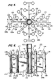
- Fig. 5 is a plan view of a WDRC spider;
- Fig. 6 is an elevational view, partially in section, of the WDRC spider of Fig. 5, taken along the line 6-6 in Fig. 5;
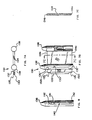
- Figs. 7A and 7B are top plan and side elevational views, respectively, of a radial vane assembly;
- Fig. 8 is an elevational view of one of the rod support mounts of a spider;
- Fig. 9 is an elevational cross-section view of a segment of a spider vane having a conventional, semi-circular leading edge cross-sectional configuration, for illustrating flow conditions;
- Fig. 10 is a perspective, broken-away and partially hidden view of an RCC rod guide and internal support plate;
- Figs. 11 and 12 are elevational and cross-sectional views of the segment of the spider vane of Fig. 9 at successive elevations relative to, and as it passes through, a corresponding slot, or channel, in a rod guide internal support plate, as in Fig. 10; and
- Figs. 13A through 13D, inclusive; are illustrative elevational cross-sectional views of segments of spider vanes having various different non-symmetrical leading edge cross-sectional configurations in accordance with the teachings of the present invention.
- The pressurized
water reactor 10 illustrated in Fig. 1 comprises avessel 12 including an upper dome, or head assembly, 12a,cylindrical sidewalls 12b, and abottom closure 12c comprising the base of thereactor 10. Radially oriented inlet nozzles 11 and outlet nozzles 13 (only one of each is seen in Fig. 1) are formed in thesidewall 12b adjacent the upper, annular end surface 12d thereof. Whereas thecylindrical sidewall 12b may be integrally joined, as by welding, to thebottom closure 12c, thehead assembly 12a is secured to the end surface 12d of thesidewall 12b so as to be removable. Thesidewall 12b defines an inner, generally annular mounting ledge 12e for supporting various internal structures, as later described herein. Thebottom closure 12c contains bottom-mounted instrumentation 14, as schematically indicated. - The
lower barrel assembly 16 comprises a generallycylindrical sidewall 17 affixed at its lower end to alower core plate 18 received on a mountingsupport 18b. Thecylindrical sidewall 17 has at its upper end a mounting ring 17a which is seated on the annular mounting ledge 12e to support theassembly 16 within thevessel 12. Thesidewall 17 is solid in the vicinity of the inlet nozzles 11 but has an aperture 17b having a nozzle ring 17c mounted therein which is aligned with and removably secured to theoutlet nozzle 13. Anupper core plate 19 is supported on a mounting support 17d affixed to the interior surface of thecylindrical sidewall 17 at a position approximately one-half the axial height thereof.Fuel rod assemblies 20 are supported within thelower barrel assembly 16 by means of bottom mounts 22 carried by thelower core plate 18 and by means of pin-like mounts 23 carried by, and extending through, theupper core plate 19. Flow holes 18a and 19a (only two of which are shown) in the lower andupper core plates lower barrel assembly 16 and therethrough in heat exchange relationship with thefuel rod assemblies 20 and thence to flow into theinner barrel assembly 24. Aneutron reflecting shield 21 extends interiorly ofsidewalls 17, around the reactor core region. - The
inner barrel assembly 24 includes acylindrical sidewall 26 which is integrally joined at its lower end to theupper core plate 19 and has secured thereto, at its upper open end, a mounting ring 26a which is received on an annular hold-down spring 27 and supported, together with the mounting ring 17a of thesidewall 17, on the mounting ledge 12e. Thesidewall 26 further includes anaperture 26b aligned with the aperture 17b and theoutput nozzle 13. Within theinner barrel assembly 24, and densely packed within thecylindrical sidewall 26, there are a plurality of rod guides disposed in closely spaced, parallel relationship with respect to each other; for simplicity of illustration, only two such rod guides are shown in Fig. 1, namely arod guide 28 housing a cluster of radiation control rods 30 (RCC), and arod guide 32 housing a cluster of water displacer rods 34 (WDRC). The rods of eachRCC cluster 30 and of each WDRC cluster 34 are connected individually to the respectively correspondingspiders rod guide 28 and corresponding mounting means 38 and 39 are provided at the respective upper and lower ends of therod guide 32, the lower mounting means 37 and 39 being used to connect the respective rod guides 28 and 32 to theupper core plate 19, and the upper mounting means 36 and 38 being used to connect the respective rod guides 28 and 32 to a lower calandria plate 52 of acalandria assembly 50. - The
calandria assembly 50 includes, in addition to the lower calandria plate 52, anupper calandria plate 54 and a plurality of parallel spacedcalandria tubes upper calandria plates 52 and 54 to which latter thecalandria tubes calandria tubes extensions calandria tubes upper calandria plate 54. - In the arrangement illustrated, only the
calandria extensions 58 project downwardly from the lower calandria plate 52 and are connected to corresponding mounting means 36 for the upper ends of the RCC rod guides 28. The upper mounting means 38, associated with the WDRC rod guides 32, may be connected through flexible linkages (not shown) to the mounting means 36 of the RCC rod guides 28. Alternatively, the WDRC rod guides 32 could be connected independently to the lower calandria plate 52, in which case thecalandria extensions 59, too, would project downwardly from the plate 52 to engage and laterally support the WDRC mounting means 38. - Disposed within the
head assembly 12a of thevessel 12 and extending upwardly from theupper calandria plate 54 there areflow shrouds calandria tubes head extensions head extensions head assembly 12a is lowered onto the end surface 12d of thevessel sidewall 12b, as later explained herein with reference to Figs. 9A and 9B. The flared ends 62a, 63a also receive therein the corresponding upper ends 60a, 61a of the flow shrouds 60, 61 in the completed assembly, as seen in Fig. 1. Thehead extensions head assembly 12a and are sealed thereto. Control rod cluster (RCC)displacement mechanisms 64 and water displacement rod cluster (WDRC)displacement mechanisms 66 are associated with therespective head extensions calandria tubes radiation control rods 30 and water displacement rods 34. The RCC displacement mechanisms (CRDMs) 64 may be of any suitable type known to the art, as may be the displacer mechanisms (DRDMs) 66 for the water displacer rod clusters (WDRCs) 34 which may be similar to the displacer mechanisms disclosed in applicant's U.S. Patent No. 4,439,054. - The respective drive rods associated with the
CRDMs 64 and theDRDMs 66 extend toward the respective clusters ofradiation control rods 30 and water displacement rods 34 and are connected at their lower ends tospiders CRDMs 64 andDRDMs 66 thus function, through the corresponding drive rods, to lower or raise theRCCs 30 and WDRCs 34 through corresponding openings (not shown) in theupper core plate 19 telescopingly into or from, respectively, the associatedfuel rod assemblies 20. As indicated in Fig. 1, the interior height D1 of thelower barrel assembly 16 is about 4.5 m, the active length D2 of thefuel rod assemblies 20 is about 3.8 m, the interior height D3 is about 4.4 m and the extent of travel, D4, of therod clusters 30 and 34 and accordingly of the corresponding CRDM and DRDM drive rods is about 3.7 m. - The
RCCs 30 are adjusted in position relatively frequently as compared to the WDRCs 34, to achieve the desired power output level from the reactor. The WDRCs 34 are inserted fully into thelower barrel assembly 16 at the initiation of each fuel cycle, and theWDRCs 32, through their respective drive rods (not shown) andDRDMs 66, then are selectively removed as the excess reactivity is depleted over the fuel cycle. Typically, this is performed by simultaneously moving a group of four WDRCs 34 from their fully inserted positions to a fully raised position within the corresponding WDRC guides 32 in a continuous and controlled withdrawal operation. More specifically, the four WDRCs 34 of a given group are selected so as to maintain a symmetrical power valance within the reactor core, when the group is withdrawn. Typically, all of the WDRCs 34 remain fully inserted in thefuel rod assemblies 20 for approximately 60% to 700/0 of the approximately 18 month fuel cycle. Groups thereof then are selectively and successively moved to the fully withdrawn position, as the excess reactivity is depleted, so as to maintain a nominal, required level of reactivity which can sustain the desired output power level, under control of the variablyadjustable RCCs 30. - The reactor coolant, or water, enters the
vessel 10 through the inlet nozzles, such as nozzle 11, thence flows downward through the annular chamber between thecylindrical sidewall 12b of thevessel 12 and thecylindrical sidewall 17 of thelower barrel assembly 16, and then reverses direction to flow through the flow holes 18a in thelower core plate 18 into and upwards through thelower barrel assembly 16, to exit the latter through the flow holes 19a in theupper core plate 19 and flow into theinner barrel assembly 24, continuing in parallel axial flow therethrough and finally exiting upwardly through flow holes 52a in the lower calandria plate 52. Thus, parallel axial flow conditions are maintained through both the lower andinner barrel assemblies calandria 50, the flow in general turns through 90° to exit radially through the outlet nozzles such asnozzle 13. The pressure of the cycle water, or reactor coolant, within thevessel 10 typically is in the range of about 153 atmospheres and provides the energy source, or fluid pressure to theDRDMs 66 for raising the DRDM drive rods from a fully inserted to a fully withdrawn position. As is apparent from Fig. 1, thespiders - Fig. 2 is a cross-sectional, schematic view, taken along the line 2-2 in Fig. 1, of the
inner barrel assembly 24 which serves to illustrate diagrammatically the dense packing of the arrays of control rod clusters (RCCs) 30 and water displacer rod clusters (WDRCs) within theinner barrel assembly 24. For ease of illustration, only thesidewall 26 of theinner barrel assembly 24 is shown, thesidewalls RCC clusters 30 and WDRC clusters 34 are disposed, in interleaved arrays, substantially across the entire cross-sectional area of theinner barrel assembly 24. This dense packing of the respective rod clusters and associated spiders thus requires careful design to assure not only that parallel flow is maintained throughout, but also that flow induced vibrations and concomitant deleterious force effects are mitigated, to the extent possible. - In Fig. 1A, there are shown three
vertical banks middle bank 42 of which is seen in Fig. 2; since thebanks banks Attachment elements 90 secure theformers sidewall 26, the outer edges 70' and 80' thereof comprising arcuate segments mating with the interior circumference of thesidewall 26, theinner edges 70" and 80" having configurations so as to mate with the periphery of the interleaved arrays of the RCC and WDRC rod guides 28 and 32. - Figs. 3 and 4 are plan and elevational views of an
RCC spider 100 which comprises a generally cylindricalcentral hub 102 having an internally threadedupper end portion 103 for connection to a drive rod (not shown) which extends, as described above, to anRCC adjustment mechanism 64 for vertically adjusting the position of thespider 100 and its associated control rods (not shown) within theRCC rod guide 28. Recesses 102a are provided to allow a metallic protective sleeve (not shown), which surrounds and overlaps the joint between the drive rod (not shown) and thehub 102, to be locked in place by indenting portions of it into the recesses 102a.Vane assemblies 106 are secured, at their inner edges, to thehub 102 and extend radially therefrom in quadrature. Eachvane assembly 106 includes a pair of cylindrical support mounts 108 each having aninterior bore 109 with an internally threadedportion 110 for threadedly receiving an externally threaded upper end portion of a control rod (not shown) to be supported from thespider 100. - Figs. 5 and 6 illustrate a
WDRC spider 120 which likewise, as theRCC spider 100, includes a generallycylindrical hub 122 with an internally threadedupper end portion 123 for threadedly receiving a drive rod connected to one of the correspondingWDRC control mechanisms 66. Thehub 122 has recesses 122a formed therein for the same purpose as explained above with respect to the recesses 102a in the hub 102 (Figs. 3 and 4). Two types ofvane assemblies hub 122 and radially extend therefrom in alternating, equiangularly displaced relationship with respect to each other. Thevane assemblies 126 are substantially similar to theRCC vane assemblies 106 shown in Figs. 3 and 4 in that they extend radially from thehub 122 in quadrature relationship, and each includes a pair of radially displaced WDRC rod support mounts 128. Eachvane assembly 127 includes integraltransverse vanes 125 extending as first and second oppositely orientedpairs 125A and 125B from the radially extending, planar vane portions 123' and 124' of theassembly 127, and each of which transverse vanes carries a WDRCrod support mount 128 at its distal end. As best seen from Fig. 5, fourvane assemblies 127 of the second type extend radially from thehub 122 in mutual quadrature relationship, each intermediate an adjacent quadrature-related pair ofvane assemblies 106 in the alternating sequence as mentioned above. Each of the WDRC rod support mounts 128 has a threadedbore 129 at its lower extremity for receiving, in threaded engagement therewith, and externally threaded upper end portions of a corresponding WDRC rod. - The configuration of the
vane assemblies vane assembly 130 as representative of either of thevane assemblies vane assembly 130 includes first and secondplanar vane elements rod support mount 138 to the hub of the associated spider, for example, thehub 102 of Figs. 3 and 4 and thehub 122 of Figs. 5 and 6. The firstplanar vane element 132 furthermore is machined to include on its radially inward and radially outward longitudinal edges, respectively,flanges 133 and 133' of reduced thickness and upper and lower steppedportions 135 and 135'. It is to be understood that the designation of a "planar vane element" or "planar vane element portion" as used herein is intended to describe a sheet-like structure, typically of metal, and having parallel, planar major surfaces substantially as shown. - With concurrent reference to Figs. 7a, 7b, and Fig. 8, the illustrative
rod support mount 138 includes a receivingslot 140 for receiving theflange 133, and upper and lower recessedportions 142 for receiving the corresponding upper and lower stepped portions 135 (135') of theflange 132. It is to be understood that the illustrative, secondplanar vane element 134 includes corresponding flanges on its longitudinal edges for interconnection of the inner andouter rod elements 138. - The
vane assembly 130 of Figs. 7a and 7b will be seen to correspond substantially identically to theRCC vane assembly 106 of Figs. 3 and 4 and theWDRC vane assembly 126 of Figs. 5 and 6. Accordingly, thevane assemblies planar vane elements flange 133 in Fig. 7b for connecting the associatedvane assembly RCC spider hub 102 andWDRC spider hub 122. This structure is illustrated for theRCC spider 100 in Fig. 4 by the receiving slot 111 in thehub 102 and theflange 115 received therein, and is illustrated for theWDRC spider 120 in Fig. 6 by the receivingslot 121 in thehub 122 and theflange 131 associated with the firstplanar vane element 123, received therein. - The second type of
vane assembly 127 of theWDRC spider 120, as seen in Fig. 6 corresponds substantially to thefirst vane assembly 126 in that it includes first and second planar vane element portions 123' and 124' which are integrally formed and extend radially from thehub 122, the first portion 123' having a longitudinal flange 131' received in a corresponding receiving slot 121' in thehub 122. Theassembly 127 furthermore includes first andsecond pairs 125A and 125B of thirdplanar vane elements 125 integrally formed with and extending transversely from the first and second vane element portions 123' and 124', thefirst pair 125A being formed intermediate the portions 123' and 124' and the second pair 125B being formed on the outer longitudinal edge of the second vane element portion 124'. Each of theelements 125 carries arod support mount 128 on its outer longitudinal edge. It will be understood that the third, or transverse,planar vane elements 125 may include similar flange structures on their outer longitudinal edges for mounting the corresponding rod support mounts 128. - In assembling the respective RCC and
WDRC spiders planar vane elements respective flanges slots 111, 121 and 121' of the associatedhubs weld beads 116 in Fig. 3 and 119 in Fig. 6. Thereafter, the joints are brazed along the entire lengths thereof. - Considering again the densely packed arrays of RCC and WDRC rod clusters as indicated in Fig. 2. it will be appreciated that the
planar vane elements 112 and 113 of theRCC spider 100 and the planar vane elements, or integral portions thereof, 123, 124, 123', 124' and 125 of theWDRC spider 120 present, in the composite, a substantial linear length of planar or sheet-like elements subjected to parallel flow conditions. The core outlet flow can produce a so-called "vortex street" behind the trailing edge of each such vane element, that is to say. its downstream edge having regard to the flow direction of reactor coolant. The resulting vortex-induced vibration may be of sufficient magnitude to produce substantial wear and shortened life. The phenomenon of immersed two-dimensional vibration due to such a vortex street being formed behind the trailing edge of a planar element when subjected to parallel flow conditions has been investigated both experimentally and theoretically. (See Blevins, R. D., FLOW-INDUCED VIBRATION, Van Nostrand Reinhold Co., 1977,page 18; R. Brepson et al., "Vibrations Induced by Von Karman Vortex Trail in Guide Vane Bends", FLOW-INDUCED STRUCTURAL VIBRATIONS, published by Sumposium Karlsruhe (Germany). August 14-16, 1972 and edited by Eduard Naudascher. published by Springer-Verlag, 1974. See also, Tebes, G. H., et al. "Hydroelastic Vibrations of Flat Plates Related to Trailing Edge Geometry", Transactions of the ASME JOURNAL OF BASIC ENGINEERING, December, 1961.) - For a vane element (e.g., any of the
vane elements 
- where fs Vortex shedding frequency [HZ].
- S = Strouhal number
- U a = Flow velocity past the vane [inch/sec.]
-
D 4 = Characteristic length, vane thickness [inch] - The Strouhal number may be dependent upon the volume of the Reynolds number (Re). The Re may be calculated as follows:

- where RΔ Reynolds number
- U Flow velocity past the vane [inch/sec.]

- p Fluid density, 6.11E-5 [lbf-sec2/inch4]
- µ fluid viscosity, 1.14E-8 [Ibf-sec/inch2]
- D Characteristic length, vane thickness [inch]
- Thus, the Reynolds number is:

- A reasonably applicable Strouhal number may be extracted from Belvins, as:

- From this, the calculated expected shedding frequency at operating conditions is:

- The shedding frequency as thus computed (i.e., fs = 240 Hz) is quite high, compared to the lowest natural frequencies of the surrounding structural components -typically fn < 100 Hz. It thus has been recognized that the primary vortex shedding function passes through the structural frequency domain of these structural components during the transition in operation of the reactor from a down condition, in which zero or low flow exists, to a full flow condition as exists in normal operation. This is contrary to the normal, desired state, which is to have the vortex shedding frequency lower than 0.8 times the lowest natural resonant frequency of the structure. Due to the variations in operating conditions, and the associated different levels of flow velocity, there is a potential for the shedding frequency (Fs) to coincide with one of the structural natural frequencies (fn). It therefore is desirable to decrease the magnitude of the shedding forcing functions on the spider by an appropriate trailing edge configuration in order to mitigate any such forced response.
- Whereas the foregoing references indicate that a number of different trailing edge configurations of planar sheets disposed in parallel flow conditions are available for decreasing the magnitude of the shedding forcing functions on such structures, the theoretical analyses do not take into account the stress conditions to which the spiders are subjected in the environment of a pressure vessel of a reactor system. Particularly, as before noted, the spiders must not only sustain substantial static weight, but must be capable of withstanding additional kinetic forces both in relation to height adjustment operations, particularly in view of the need for assured, rapid translational movement of the RCC rod clusters when rapid shutdown of a reactor is required and due to flow induced forces. These design conditions must also be achieved in a limited axial space envelope.
- Conventional vane element designs, taking into account general hydrostatic flow conditions, have been based on the belief that a trailing edge configuration affording a gradual transition from the parallel planar surfaces serves to improve flow characteristics (e.g., trailing edge cross-sectional configurations ranging from semicircular to more gradually tapered forms). In fact, it has been determined that the tapered or curved surfaces extend the area of flow separation and expand the surface area subjected to the turbulent vortex which forms in the flow as it passes beyond the vane element. Moreover, tapered or restraint trailing edge configurations which reduce the flow separation problem have a reduced amount of structural material in the cross-section of the trailing edge, and this weakens the vane for a given height and thickness or, conversely, requires that the longitudinal dimension of the vane element (i.e., the axial height) be increased in order to afford sufficient structural strength. Weakening of the vane elements is not acceptable, and the alternative of increasing height is not practical in view of the corresponding increase in height of the inner barrel assembly which would be required to accommodate the increase vane height in view of the significant concomitant increase in the cost of the vessel which would result.
- Contrary to the standard semicircular cross-section trailing edge designs of prior art vane elements, and in accordance with the present invention, it has been determined that a square cross-sectional trailing edge configuration of the vane elements of the rod supporting spiders is near optimum, taking into account vortex in the flow and shedding frequency considerations, along with the required structural strength of the vane elements and the associated spiders and the restrictive allowable space envelope. The significant and determinative factors are to mitigate the shedding function so as to reduce the vibratory response of the structure, while maintaining maximum strength of the vane elements of a given size -- and to achieve these results in a structure which is easy to manufacture, in the interests of mitigating costs. The square, or substantially square, cross-sectional configuration of the trailing edge has been determined to meet these design and operational criteria, and is deemed surprising and unexpected, as a departure from conventional designs. Moreover, the square cross-sectional trailing edge configuration contributes to ease, and thus lower costs, of manufacture of the vane elements -- as contrasted to the conventional semicircular and/or other tapered cross-sectional trailing edge configurations heretofore employed.
- Accordingly, the
vane elements representative assembly 130 of Figs. 7a and 7c have squarecross-sectional trailing edges vane elements cross-sectional trailing edges - It is to be understood, however, that in accordance with the present invention, the leading edges particularly have non-symmetrical cross-sectional configurations, such as those of Figs. 13a through 13d or variations thereof, as now more fully explained, for avoiding the switching or oscillatory loadings to which prior art spider vanes are subjected as a result of flow-induced effects. Particularly, Fig. 9 illustrates in partial cross-section, a segment of a
vane 134 as in Fig. 7c having aleading edge 134a of semicircular cross-section. The semi-circular configuration suggests itself as being nearly the obvious choice in the environment of the parallel axial flow F to which thevane 134 is subjected, the flow dividing equally about thevane 134 with respect to the plane ofsymmetry 136 which intersects the semicircularleading edge 134a at aflow stagnation line 138. The configuration thus, at least under ideal conditions, results in no net lateral loading on thevane 134 -- a seemingly obvious, desirable feature. It will be understood, of course, that theflow stagnation line 138 appears as only a single point and the plane ofsymmetry 136 appears as a line, in the two dimensional illustration of Fig. 9. - In accordance with the present invention, the apparent desirability of providing a symmetrical cross-sectional configuration for the leading edge of a spider vane, be it of semicircular cross-section as in Fig. 9 or another, is in fact undesirable. This result is explained with reference to Figs. 10, 11 and 12. In Fig. 10, there is shown in a broken-away and partially hidden illustration, a perspective view of a section of the RCC rod guide 28 (see Fig. 1) which accommodates a RCC rod cluster and its associated spider 100 (see Figs. 3 and 4), taken in the section intermediate the upper and lower mounting means 36 and 37 thereof. Within the sidewall of the
RCC rod guide 28, at spaced elevations, there are disposed horizontally orientedsupport plates 150 having an outer peripheral configuration corresponding to the interior surface of the side wall of theRCC rod guide 28. Thesupport plate 150 includes aninterior opening 152 for accommodating axial movement therethrough of a cylindricalrod support mount 108 and its associated rod, and a slotted opening, or channel, 154 for accommodating a corresponding vane section, e.g.. vane 134 (Figs. 7a, 7b and 7c) of the associatedRCC spider 100. As will be appreciated. theRCC spider 100 temporarily resides within each of thesupport plates 150 during the required vertical movement thereof for the normal operational control of the reactor power output. - The broken-away vertical cross-sectional views of Figs. 11 and 12 illustrate the condition of the
vane 134 at successive stages of its vertical movement as it passes through theslot 154 of an associatedsupport plate 150. As shown in Fig. 11. the normal parallel axial flow which is symmetrically distributed when thevane 134 is in free space (i.e., not within a support plate 150) and as shown in Fig. 9, is altered significantly when thevane 134 is within theslot 154 in asupport plate 150. Specifically, the presence of thevane 134 within theslot 154 creates a significant flow restriction within the normally open, or free area of theslot 154 in thesupport plate 150. The impinging flow Fi nevertheless must be maintained, with the result that a much higher velocity flow occurs through the now constrictedslot 154 before emerging as the outlet flow Fo. - At a small range of the elevational locations of the
vane 134, the flow restriction produces vibration of thevane 134 and of its associated spider. The effect is believed to be most pronounced when theleading edge 134a of thevane 134 is within theslot 154 of thesupport plate 150, as illustrated in Fig. 12. As shown therein, as the flow Fi enters the entrance ofslot 154, it is confronted by theleading edge 134a of thevane 134. Due to the symmetrical configuration of the leading edge 14a (i.e., semicircular or other), the flow pattern around the leading edge and emerging as the outlet flow Fo may switch from one side of the vane to the other, and thus relatively to the plane ofsymmetry 136. It is believed that the flow switching mechanism occurs in the following manner. - Due to the turbulent condition of the flow, as illustrated in Ft in Fig. 12, a greater proportion of the inlet flow Fi will be directed to one side of the
vane 134, the flow rate gradually building, or increasing, on that side and thereby initially increasing the lateral loading (i.e., in a direction perpendicular to the plane of symmetry PL/SYM) and thereby urging the vane away from the corresponding side wall of theslot 154 and increasing the clearance therethrough, concomitantly increasing the total flow through that side. The increased velocity of the flow through that more opened side, however, produces a decrease in the corresponding pressure on that side of the vane; at the same time, the opposite side of the vane, i.e., that side in which the flow in more significantly constricted or blocked, starts to develop a higher static pressure. The result is that the vane then is pushed laterally towards the opposite side of the slot where the flow rate is higher. Thereafter, the action repeats. Accordingly, there is produced a switching or oscillatory lateral loading on thevane 134 which correspondingly is transmitted to the spider and its associated hub as well as to the control rods supported by the spider and the drive system for the spiders. The resulting structural vibration clearly is potentially detrimental to the structural integrity of both the directly affected components and the associated components. - In accordance with the present invention, it has been recognized that a major factor in the initialization of the switching, or oscillatory loading phenomenon is the symmetrical cross-section of the vane leading edge. As before noted, this symmetry enables the static forces to build up on the side of the vane for which the corresponding flow has been reduced, because the most leading line, or edge, 138 (i.e., the flow stagnation line) is at the geometric plane of
symmetry 136 of thevane 134, and the flow Fi encounters a significant frontal area on that side of the vane. - The present invention thus provides for off-setting the flow stagnation line of the vane leading edge away from the plane of symmetry 136a, 136b, 136c, 136d. Figs. 13A through 13D illustrate exemplary such cross-sectional configurations, in each of which the static flow line 138a, 138b, 138c, 138d is shifted away from the plane of symmetry 136a, 136b, 136c, 136d of the vane, as a geometric whole (i.e., relative to its major planar surfaces). More particularly,
vane 134a of Fig. 13A has a leading edge cross-section of a non-symmetrical, convex configuration. The leading edge cross-sectional configuration ofvane 134b of Fig. 13B defines a single acute angle with respect to one of the major planar surfaces thereof, i.e., the left major planar surface as illustrated in Fig. 13B, in which the flow stagnation line 138b is displaced a maximum distance from the plane of symmetry 136b. The leading edge cross-sectional configuration of the vane element 134c of Fig. 13C is convex, as in Fig. 13A, but is defined by a double acute angle relative to the respective major planar surfaces thereby to offset the flow stagnation line 138c from the plane of symmetry 136c. Finally, the leading edge cross-sectional configuration of the vane element 134d of Fig. 13D defines a truncated acute angle with respect to one of the major planar surfaces, i.e., the right surface as shown in Fig. 13D; the flow stagnation line 138d again is offset from the plane of symmetry 136d, but to a lesser degree than in Fig. 13B. As is apparent from Figs. 13A through 13D, the extent of offset of theflow stagnation line 138 from the plane ofsymmetry 136 may be adjusted by the configuration of the leading edge cross-section, to the extent desired. Any of the configurations of Figs. 13A through 13D or variations thereof, which meet the aforestated criterion, when adapted as the leading edge geometry of a spider vane, will serve to mitigate the lateral vibratory loading on the vane and the resultant switching, or oscillatory, loadings applied thereto and the resulting vibration. With reference to the planar views of theRCC spider 100 in Fig. 3 and theWDRC spider 120 in Fig. 5, it will be appreciated that the vanes are symmetrically disposed in generally diametric relationship about the respectivecentral hubs - A non-symmetrical vane configuration, illustratively any of Figs. 13A through 13D, may be afforded on each of the four vanes of the
RCC spider 106 to produce a net torque in a given direction, e.g., counter-clockwise, on the drive rod connected to the spider; as a result, all similarly situation planar surfaces of the spider vanes would be urged against the corresponding, contiguous side wall of theslot 154 in thesupport plate 150 as those elements are illustrated in Figs. 10 to 12. Alternatively, the offsets of the non-symmetrical leading edge configurations of successive pairs of angularly displaced vane elements, relative to the respective planes of symmetry, may be oppositely directed, progressing about thecentral hub 102, so as to produce laterally diagonal loading on the central hub of the spider. The non-symmetrical configura tion of the spider vane leading edges, in any such arrangement, serves to eliminate the switching or oscillatory movement of the vanes and thus overcomes the resulting vibratory loading and the related, detrimental effects which are produced by the conventional, symmetrical leading edge configuration of spider vanes. The particular configuration selected is best determined from consideration of environmental factors within a given pressure vessel. For example, the configuration of Fig. 13B is optimum with regard to producing non-symmetrical lateral loading but is less desirable from the standpoint of the bending strength of the vane leading edge. The configurations of Figs. 13A and 13D afford greater strength than that of Fig. 13B, but, due to the reduced off-set, correspondingly have a reduced capability of eliminating the flow switching problem. The configuration of Fig. 13C has flow-switching and strength characteristics intermediate those of Figs. 13A and 13B. The configuration of Fig. 13D is easiest to manufacture whereas those of Figs. 13B and 13C and somewhat more difficult, but easier than that of Fig. 13A. All thereof share the common characteristic that they comprise improvements over the standard, semicircular cross-sectional configuration of conventional spider vanes.
Claims (7)
Applications Claiming Priority (2)
| Application Number | Priority Date | Filing Date | Title |
|---|---|---|---|
| US07/091,056 US4863678A (en) | 1985-12-09 | 1987-08-27 | Rod cluster having improved vane configuration |
| US91056 | 1987-08-27 |
Publications (3)
| Publication Number | Publication Date |
|---|---|
| EP0305159A2 true EP0305159A2 (en) | 1989-03-01 |
| EP0305159A3 EP0305159A3 (en) | 1990-01-10 |
| EP0305159B1 EP0305159B1 (en) | 1993-11-18 |
Family
ID=22225727
Family Applications (1)
| Application Number | Title | Priority Date | Filing Date |
|---|---|---|---|
| EP88307830A Expired - Lifetime EP0305159B1 (en) | 1987-08-27 | 1988-08-24 | Rod cluster spider having improved vane configuration |
Country Status (5)
| Country | Link |
|---|---|
| US (1) | US4863678A (en) |
| EP (1) | EP0305159B1 (en) |
| JP (1) | JPH01126592A (en) |
| DE (1) | DE3885678T2 (en) |
| ES (1) | ES2045134T3 (en) |
Cited By (2)
| Publication number | Priority date | Publication date | Assignee | Title |
|---|---|---|---|---|
| US9334756B2 (en) | 2012-09-28 | 2016-05-10 | United Technologies Corporation | Liner and method of assembly |
| US10066548B2 (en) | 2013-03-15 | 2018-09-04 | United Technologies Corporation | Acoustic liner with varied properties |
Families Citing this family (14)
| Publication number | Priority date | Publication date | Assignee | Title |
|---|---|---|---|---|
| DE3925617A1 (en) * | 1989-08-02 | 1991-02-07 | Siemens Ag | DEVICE FOR CONTROLLING THE POWER OUTPUT OF A REACTOR WITH STEERING STICKS |
| IL153271A0 (en) * | 2002-12-04 | 2003-07-06 | Krausz Metal Ind Ltd | Clamp to anode connection |
| US9336910B2 (en) | 2010-10-07 | 2016-05-10 | Bwxt Nuclear Energy, Inc. | Control rod/control rod drive mechanism couplings |
| US9378853B2 (en) | 2010-10-21 | 2016-06-28 | Bwxt Nuclear Energy, Inc. | Support structure for a control rod assembly of a nuclear reactor |
| US9805832B2 (en) | 2012-02-27 | 2017-10-31 | Bwxt Mpower, Inc. | Control rod drive mechanism (CRDM) mounting system for pressurized water reactors |
| US9911512B2 (en) | 2012-02-27 | 2018-03-06 | Bwxt Mpower, Inc. | CRDM internal electrical connector |
| US9754688B2 (en) | 2012-04-17 | 2017-09-05 | Bwx Technologies, Inc. | Suspended upper internals for compact nuclear reactor including a lower hanger plate |
| US10102932B2 (en) | 2012-04-17 | 2018-10-16 | Bwxt Mpower, Inc. | Power distribution plate for powering internal control rod drive mechanism (CRDM) units |
| US9767930B2 (en) | 2012-04-17 | 2017-09-19 | Bwxt Mpower, Inc. | Suspended upper internals for compact nuclear reactor including a mid-hanger plate |
| US9972407B2 (en) | 2012-04-17 | 2018-05-15 | Bwxt Mpower, Inc. | Small modular reactor fuel assembly |
| US9887015B2 (en) | 2012-04-17 | 2018-02-06 | Bwxt Mpower, Inc. | Suspended upper internals with tie rod couplings for compact nuclear reactor |
| US10229760B2 (en) | 2013-03-15 | 2019-03-12 | Bwxt Mpower, Inc. | CRDM with separate scram latch engagement and locking |
| US9865364B2 (en) | 2013-03-15 | 2018-01-09 | Bwxt Mpower, Inc. | CRDM with separate SCRAM latch engagement and locking |
| CN113409965A (en) * | 2021-06-17 | 2021-09-17 | 中国核动力研究设计院 | Integrated control rod assembly star frame and control rod assembly |
Family Cites Families (12)
| Publication number | Priority date | Publication date | Assignee | Title |
|---|---|---|---|---|
| US3048532A (en) * | 1961-05-24 | 1962-08-07 | Ii Arthur G Thorp | Cruciform control rod joint |
| US3314859A (en) * | 1963-12-05 | 1967-04-18 | Combustion Eng | Nuclear reactor fuel assembly-control rod organization |
| US3481832A (en) * | 1967-04-14 | 1969-12-02 | Combustion Eng | Nuclear reactor core and control element arrangement |
| US4035230A (en) * | 1973-02-20 | 1977-07-12 | Combustion Engineering, Inc. | Shock buffer for nuclear control assembly |
| DE3027562A1 (en) * | 1980-07-21 | 1982-02-11 | Kraftwerk Union AG, 4330 Mülheim | Test of boiling water reactor control rods - with portion of fuel elements removed and remainder held fixed |
| US4439054A (en) * | 1980-12-16 | 1984-03-27 | Westinghouse Electric Corp. | Latching mechanism |
| US4432934A (en) * | 1980-12-16 | 1984-02-21 | Westinghouse Electric Corp. | Displacer rod for use in a mechanical spectral shift reactor |
| US4481164A (en) * | 1982-03-17 | 1984-11-06 | The United States Of America As Represented By The United States Department Of Energy | Reactivity control assembly for nuclear reactor |
| JPS60159509A (en) * | 1984-01-26 | 1985-08-21 | Akira Muramoto | Gas burner for use in cooking apparatus |
| JPS60158812A (en) * | 1984-01-31 | 1985-08-20 | 東芝テック株式会社 | Juicer |
| US4820058A (en) * | 1984-07-26 | 1989-04-11 | Westinghouse Electric Corp. | Control rod end plug with a stabilizing configuration |
| EP0225805B1 (en) * | 1985-12-09 | 1990-03-21 | Westinghouse Electric Corporation | Rod cluster spider having improved vane configuration |
-
1987
- 1987-08-27 US US07/091,056 patent/US4863678A/en not_active Expired - Fee Related
-
1988
- 1988-08-24 ES ES88307830T patent/ES2045134T3/en not_active Expired - Lifetime
- 1988-08-24 DE DE3885678T patent/DE3885678T2/en not_active Expired - Fee Related
- 1988-08-24 EP EP88307830A patent/EP0305159B1/en not_active Expired - Lifetime
- 1988-08-26 JP JP63212289A patent/JPH01126592A/en active Pending
Cited By (3)
| Publication number | Priority date | Publication date | Assignee | Title |
|---|---|---|---|---|
| US9334756B2 (en) | 2012-09-28 | 2016-05-10 | United Technologies Corporation | Liner and method of assembly |
| US10066548B2 (en) | 2013-03-15 | 2018-09-04 | United Technologies Corporation | Acoustic liner with varied properties |
| USRE48980E1 (en) | 2013-03-15 | 2022-03-22 | Raytheon Technologies Corporation | Acoustic liner with varied properties |
Also Published As
| Publication number | Publication date |
|---|---|
| ES2045134T3 (en) | 1994-01-16 |
| DE3885678D1 (en) | 1993-12-23 |
| DE3885678T2 (en) | 1994-06-30 |
| EP0305159A3 (en) | 1990-01-10 |
| US4863678A (en) | 1989-09-05 |
| EP0305159B1 (en) | 1993-11-18 |
| JPH01126592A (en) | 1989-05-18 |
Similar Documents
| Publication | Publication Date | Title |
|---|---|---|
| EP0305159B1 (en) | Rod cluster spider having improved vane configuration | |
| US6526116B1 (en) | Nuclear fuel assembly with hydraulically balanced mixing vanes | |
| US4772447A (en) | Device for the spacing and holding in place of fuel rods in a fuel assembly | |
| EP0283836B1 (en) | Thin walled channel | |
| US4231843A (en) | Guide tube flow diffuser | |
| US5533078A (en) | Nuclear fuel assembly for a pressurized water reactor | |
| US5237595A (en) | Guide plate for guide tubes used in nuclear reactors | |
| US4759904A (en) | Pressurized water reactor having improved calandria assembly | |
| EP1909292A1 (en) | Nuclear reactor fuel assemblies | |
| KR20130139971A (en) | Support structure for a control rod assembly of a nuclear reactor | |
| US4857264A (en) | Frictionally loaded top end supports for cantilever-mounted rod guides of a pressurized water reactor | |
| EP0555081A1 (en) | Spacer with steam separator | |
| EP2628159B1 (en) | Nuclear fuel assembly hold down spring | |
| EP0225805B1 (en) | Rod cluster spider having improved vane configuration | |
| EP0222373B1 (en) | Top end support for water displacement rod guides of pressurized water nuclear reactor | |
| JPH0915362A (en) | Boiling Water Reactor Fuel Assembly | |
| JPH04232895A (en) | Guide-tube inserted-material assembly in in-pile structure assembly | |
| US4820058A (en) | Control rod end plug with a stabilizing configuration | |
| USRE34246E (en) | Thin walled channel | |
| EP0526777B1 (en) | Boiling water reactor fuel assembly comprising water rods | |
| EP0158812B1 (en) | Control rod spider assembly for a nuclear reactor fuel assembly | |
| CN86107837A (en) | The cluster guide piece that has centering and vibrationproof locating device that is used for nuclear reactor | |
| EP0532844A1 (en) | Nuclear fuel assembly comprising a lower end fitting with flow diffusers | |
| JPS63186183A (en) | pressurized water reactor | |
| EP0363710A2 (en) | Combined support column and guide tube for use in a nuclear reactor |
Legal Events
| Date | Code | Title | Description |
|---|---|---|---|
| PUAI | Public reference made under article 153(3) epc to a published international application that has entered the european phase |
Free format text: ORIGINAL CODE: 0009012 |
|
| AK | Designated contracting states |
Kind code of ref document: A2 Designated state(s): BE CH DE ES FR GB IT LI SE |
|
| PUAL | Search report despatched |
Free format text: ORIGINAL CODE: 0009013 |
|
| AK | Designated contracting states |
Kind code of ref document: A3 Designated state(s): BE CH DE ES FR GB IT LI SE |
|
| 17P | Request for examination filed |
Effective date: 19900124 |
|
| 17Q | First examination report despatched |
Effective date: 19920213 |
|
| GRAA | (expected) grant |
Free format text: ORIGINAL CODE: 0009210 |
|
| ITF | It: translation for a ep patent filed | ||
| AK | Designated contracting states |
Kind code of ref document: B1 Designated state(s): BE CH DE ES FR GB IT LI SE |
|
| REF | Corresponds to: |
Ref document number: 3885678 Country of ref document: DE Date of ref document: 19931223 |
|
| ET | Fr: translation filed | ||
| REG | Reference to a national code |
Ref country code: ES Ref legal event code: FG2A Ref document number: 2045134 Country of ref document: ES Kind code of ref document: T3 |
|
| PGFP | Annual fee paid to national office [announced via postgrant information from national office to epo] |
Ref country code: SE Payment date: 19940829 Year of fee payment: 7 |
|
| PLBE | No opposition filed within time limit |
Free format text: ORIGINAL CODE: 0009261 |
|
| STAA | Information on the status of an ep patent application or granted ep patent |
Free format text: STATUS: NO OPPOSITION FILED WITHIN TIME LIMIT |
|
| 26N | No opposition filed | ||
| EAL | Se: european patent in force in sweden |
Ref document number: 88307830.5 |
|
| PGFP | Annual fee paid to national office [announced via postgrant information from national office to epo] |
Ref country code: FR Payment date: 19950712 Year of fee payment: 8 |
|
| PGFP | Annual fee paid to national office [announced via postgrant information from national office to epo] |
Ref country code: BE Payment date: 19950719 Year of fee payment: 8 |
|
| PGFP | Annual fee paid to national office [announced via postgrant information from national office to epo] |
Ref country code: CH Payment date: 19950725 Year of fee payment: 8 |
|
| PG25 | Lapsed in a contracting state [announced via postgrant information from national office to epo] |
Ref country code: SE Effective date: 19950825 |
|
| PGFP | Annual fee paid to national office [announced via postgrant information from national office to epo] |
Ref country code: DE Payment date: 19950929 Year of fee payment: 8 |
|
| EUG | Se: european patent has lapsed |
Ref document number: 88307830.5 |
|
| PGFP | Annual fee paid to national office [announced via postgrant information from national office to epo] |
Ref country code: ES Payment date: 19960814 Year of fee payment: 9 |
|
| PG25 | Lapsed in a contracting state [announced via postgrant information from national office to epo] |
Ref country code: LI Effective date: 19960831 Ref country code: CH Effective date: 19960831 Ref country code: BE Effective date: 19960831 |
|
| BERE | Be: lapsed |
Owner name: WESTINGHOUSE ELECTRIC CORP. Effective date: 19960831 |
|
| REG | Reference to a national code |
Ref country code: CH Ref legal event code: PL |
|
| PG25 | Lapsed in a contracting state [announced via postgrant information from national office to epo] |
Ref country code: FR Effective date: 19970430 |
|
| PG25 | Lapsed in a contracting state [announced via postgrant information from national office to epo] |
Ref country code: DE Effective date: 19970501 |
|
| REG | Reference to a national code |
Ref country code: FR Ref legal event code: ST |
|
| PG25 | Lapsed in a contracting state [announced via postgrant information from national office to epo] |
Ref country code: ES Free format text: LAPSE BECAUSE OF NON-PAYMENT OF DUE FEES Effective date: 19970825 |
|
| PGFP | Annual fee paid to national office [announced via postgrant information from national office to epo] |
Ref country code: GB Payment date: 19990702 Year of fee payment: 12 |
|
| PG25 | Lapsed in a contracting state [announced via postgrant information from national office to epo] |
Ref country code: GB Free format text: LAPSE BECAUSE OF NON-PAYMENT OF DUE FEES Effective date: 20000824 |
|
| GBPC | Gb: european patent ceased through non-payment of renewal fee |
Effective date: 20000824 |
|
| REG | Reference to a national code |
Ref country code: ES Ref legal event code: FD2A Effective date: 19980910 |
|
| PG25 | Lapsed in a contracting state [announced via postgrant information from national office to epo] |
Ref country code: IT Free format text: LAPSE BECAUSE OF NON-PAYMENT OF DUE FEES Effective date: 20050824 |