EP0311019B1 - Schrittmacher zur Herzstimulierung synchron zur Vorhofsaktivität - Google Patents
Schrittmacher zur Herzstimulierung synchron zur Vorhofsaktivität Download PDFInfo
- Publication number
- EP0311019B1 EP0311019B1 EP88116410A EP88116410A EP0311019B1 EP 0311019 B1 EP0311019 B1 EP 0311019B1 EP 88116410 A EP88116410 A EP 88116410A EP 88116410 A EP88116410 A EP 88116410A EP 0311019 B1 EP0311019 B1 EP 0311019B1
- Authority
- EP
- European Patent Office
- Prior art keywords
- impedance
- signal
- heart
- generating
- pacer
- Prior art date
- Legal status (The legal status is an assumption and is not a legal conclusion. Google has not performed a legal analysis and makes no representation as to the accuracy of the status listed.)
- Expired - Lifetime
Links
Images

Classifications
-
- A—HUMAN NECESSITIES
- A61—MEDICAL OR VETERINARY SCIENCE; HYGIENE
- A61N—ELECTROTHERAPY; MAGNETOTHERAPY; RADIATION THERAPY; ULTRASOUND THERAPY
- A61N1/00—Electrotherapy; Circuits therefor
- A61N1/18—Applying electric currents by contact electrodes
- A61N1/32—Applying electric currents by contact electrodes alternating or intermittent currents
- A61N1/36—Applying electric currents by contact electrodes alternating or intermittent currents for stimulation
- A61N1/362—Heart stimulators
- A61N1/365—Heart stimulators controlled by a physiological parameter, e.g. heart potential
- A61N1/36514—Heart stimulators controlled by a physiological parameter, e.g. heart potential controlled by a physiological quantity other than heart potential, e.g. blood pressure
- A61N1/36521—Heart stimulators controlled by a physiological parameter, e.g. heart potential controlled by a physiological quantity other than heart potential, e.g. blood pressure the parameter being derived from measurement of an electrical impedance
Definitions
- the present invention relates to a pacer for stimulating the heart of a patient synchronous to atrial activity.
- P-synchronous pacers require a sensing element in the atrium to measure the atrial contraction. This requires, in turn, the use of a separate lead in the atrium or a special ventricular lead with a separate floating electrode in the atrium. Either approach requires a skilled surgeon to successfully implant such a system. It is furthermore subject to sensing problems at a later date.
- a p-synchronous pacer as the one referred to above is, for example, described in the Journal "Thoracic and Cardiovascular Surgery", Vol. 46, No. 4 (October, 1963) in an article entitled “Chronic Postsurgical Complete Heart Block” by Lillehei et al. on pages 436-456.
- pacers relying on impedance measurements for their control are also known.
- One such pacer is, for example, described in GB-A-2 070 282.
- the '282 pacer includes circuitry for determining a trend in (stroke volume indicating) peak-to-peak impedance swing for subsequent heart cycles. If a trend is present, the AV-time of the pacer can be adjusted to maximise stroke volume.
- this pacer makes use of separate atrial and ventricular impedance measurement electrodes.
- the invention is defined in claim 1.
- the impedance instead of measuring the electric potential evoked by the atrium, the impedance, including the ventricular impedance, is monitored continuously.
- This impedance measurement indirectly detects the intraventricular volume as one component of the overall body impedance.
- the atrium contracts, the ventricular impedance is lowered when the atrial blood enters the ventricle. This results in a rapid inflection (notch) in the overall impedance signal.
- notch a signal corresponding to the p-wave can be detected from any ventricular electrode without requiring additional sensing in the atrium. This signal can then be used to trigger the ventricular stimulus (VVI pacing).
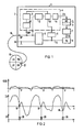
- Figure 1 is a schematic block diagram of a heart pacer synchronous to atrial activity according to the principles of the present, invention, for a unipolar impedance measurement in the right ventrical of a patient's heart.
- Figure 2 is an impedance diagram corresponding to an impedance measurement as utilized by the heart pacer synchronous to atrial activity according to the principles of the present invention.
- Figure 3 is a detailed circuit diagram of the delta modulator and the event detector.
- the pacer 1 comprises a metallic housing 2 encapsuling electrical components.
- the illustrated components are a stimulation pulse generator 3, which generates stimulation pulses SP, an impedance measuring unit 4, a delta modulator 5, comprising a comparator 6, an event detector 7, a signal delay unit 8, and a blanking control unit 9.
- the impedance measuring unit 4 includes a high-frequency (e.g. 4 kHz) current generator 10, with oscillator 11, a pre-amplifier 12, a demodulator 13, which can be blanked by the blanking control unit 9, and a band-pass filter 14 (0,1 Hz - 20 Hz).
- the signal output of the stimulation pulse generator 3 is electrically connected with the right ventrical RV of the patient's heart 15 through pacing lead 16 and pacing electrode 17.
- the indifferent electrode (indicated by reference number 18) is formed by metallic housing 2 of the pacer 1.
- the left ventricle of the heart 15 is indicated with LV.
- the right and left atriums are indicated by RA and LA, respectively.
- a high frequency current IHF is introduced by the high frequency current generator 10 through lead 16 to pacing electrode 17 and, from there, back to indifferent electrode 18 (metallic housing 2 of pacer 1).
- the current signal received from the body is a measure of the overall impedance between pacing electrode 17, located in the right ventricle, and metallic housing 2 of the pacer (uni-polar impedance measurement).
- a bipolar impedance measurement could equally well be used, by locating the indifferent electrode 18, for example, close to the pacing electrode 17 at another point on lead 16, e.g. by fabricating lead 16 as a bipolar catheter.
- the overall impedance is measured by the elements 12 to 14 of the impedance measuring unit 4.
- the impedance signal at the output of the impedance measuring unit 4 is generally designated by IS.
- the impedance includes intraventricular (e.g. end systolic, end diastolic volume) and extraventricular components (e.g. respiratory cavitary changes).
- intraventricular e.g. end systolic, end diastolic volume
- extraventricular components e.g. respiratory cavitary changes
- the delta modulator 5 is tuned to a maximum slope, which exceeds less steep non-atrial components of the impedance signal IS.
- the delta modulator 5, in conjunction with the event detector 7, generates the detector signal DS when a rapid inflection in the impedance signal IS exceeds the maximum slope of the signal MS from the delta modulator 5.
- This signal DS which corresponds to the occurance of a p-wave, after a given delay time t D , triggers the stimulation pulse generator 3 to generate a stimulation pulse SP.
- the blanking control unit 9 to blank the demodulator 13 of the impedance measuring unit 4 (blanking time: e.g. 40 ms) while the stimulation pulse SP is generated.
- the trigger signal for triggering the stimulation pulse generator 3 and the blanking control unit 9 is generally designated TS.
- an electrocardiogram comprising p-waves is shown above the impedance signal IS, as a function of time t.
- ECG electrocardiogram
- the delta modulator 5 comprises comparator 6, a bistable multivibrator 20, current generators 21, an integration capacitor 22, and an exclusive-OR-gate 23.
- the inverting input of comparator 6 is connected to a reference voltage V REF .
- the bistable multivibrator 20 is clocked by a clock frequency f1 (e.g. 16 kHz).
- the event detector 7 comprises a counter 24, which is clocked by a frequency f2 (e.g. 4 kHz), and a comparator 25.
- the comparator 25 compares the output signal S1 of the counter 24 with a time reference signal S2. In case that the output signal S1 meets the time reference signal S2, a detector signal DS is generated.
- the operation of the circuit of Figure 3 is as follows.
- the impedance signal IS including inflections 19, is supplied to the delta modulator 5, as indicated in Figure 3.
- the opposite side of integration capacitor 22 transfers the signal to the non-inverting input of comparator 6 with a slope of either +I/C or -I/C, wherein I is the current of current generator 21 (programmable) and C is the capacity of the integration capacitor 22.
- the bistable multivibrator 20 switches from one state to the other, the exclusive-OR-gate 23 zeros the counter 24 in the event detector 7.
- the bistable multivibrator 20 When the slope of the impedance signal IS exceeds +I/C or falls below -I/C (namely, upon the occurrence of an inflection 19), the bistable multivibrator 20 does not switch. As a result, the time counter 24 of event detector 7 is not zeroed. The output signal S1 of the time counter 24 increases until it meets the time reference signal S2. A detection signal DS is generated, as indicated in Figure 2, by pulses 26.
Landscapes
- Health & Medical Sciences (AREA)
- Cardiology (AREA)
- Heart & Thoracic Surgery (AREA)
- Life Sciences & Earth Sciences (AREA)
- Biomedical Technology (AREA)
- Biophysics (AREA)
- Physiology (AREA)
- Engineering & Computer Science (AREA)
- Hematology (AREA)
- Nuclear Medicine, Radiotherapy & Molecular Imaging (AREA)
- Radiology & Medical Imaging (AREA)
- Animal Behavior & Ethology (AREA)
- General Health & Medical Sciences (AREA)
- Public Health (AREA)
- Veterinary Medicine (AREA)
- Electrotherapy Devices (AREA)
Claims (2)
- Schrittmacher (1) zur ventrikulären Stimulation des Herzens (15) eines Patienten mit:a) Mitteln (3) zum Erzeugen von Stimulationsimpulsen (SP),b) einer Schrittmacherelektrode (17), die elektrisch mit den Mitteln (3) zum Erzeugen von Stimulationsimpulsen verbunden ist und zur Positionierung im Ventrikel (RV) des Herzens (15) ausgebildet ist,c) mit der Schrittmacherelektrode verbundenen Mitteln (4) zum Ausfuhren einer Impedanzmessung, wobei die Impedanz eine ventrikuläre Impedanz beinhaltet, und zum Erzeugen eines Impedanzsignals (IS) in Abhängigkeit von der gemessenen Impedanz,d) Mitteln (5,7) zum Detektieren einer schnellen Krümmung (19) in dem Impedanzsignal (IS) und zum Erzeugen eines entsprechenden Detektionssignals (DS), unde) Mitteln (8) zum zeitverzögerten Triggern der Mittel (3) zum Erzeugen von Stimulationsimpulsen in Abhängigkeit von dem Auftreten des Detektionssignals (DS), so dass die Mittel (3) zum Erzeugen von Stimulationsimpulsen (SP) einen Stimulationsimpuls (SP) mit einer, der atrio-ventrikulären Verzögerung des Herzens (15) des Patienten entsprechenden Zeitverzögerung (t₀) erzeugen.
- Schrittmacher (1) nach Anspruch 1, wobei die Mittel (5,7) zum Detektieren einer schnellen Krümmung (19) einen Deltamodulator (5) aufweisen, der auf eine maximale Steigung abgestimmt ist, welche weniger steile nichtatrielle Komponenten des Impedanzsignals (IS) übersteigt, und wobei die Mittel (5,7) ferner einen Komparator (6) aufweisen, der das Detektionssignal (DS) erzeugt, wenn eine schnelle Krümmung (19) in dem Impedanzsignal (IS) die maximale Steigung eines Ausgangssignals (MS) des Deltamodulators (5) übersteigt.
Applications Claiming Priority (2)
| Application Number | Priority Date | Filing Date | Title |
|---|---|---|---|
| US105671 | 1987-10-07 | ||
| US07/105,671 US4905696A (en) | 1987-10-07 | 1987-10-07 | Method and apparatus for P-synchronously stimulating the heart of a patient |
Publications (2)
| Publication Number | Publication Date |
|---|---|
| EP0311019A1 EP0311019A1 (de) | 1989-04-12 |
| EP0311019B1 true EP0311019B1 (de) | 1992-12-30 |
Family
ID=22307135
Family Applications (1)
| Application Number | Title | Priority Date | Filing Date |
|---|---|---|---|
| EP88116410A Expired - Lifetime EP0311019B1 (de) | 1987-10-07 | 1988-10-04 | Schrittmacher zur Herzstimulierung synchron zur Vorhofsaktivität |
Country Status (5)
| Country | Link |
|---|---|
| US (1) | US4905696A (de) |
| EP (1) | EP0311019B1 (de) |
| JP (1) | JP2703287B2 (de) |
| AU (1) | AU607372B2 (de) |
| DE (1) | DE3877113T2 (de) |
Families Citing this family (19)
| Publication number | Priority date | Publication date | Assignee | Title |
|---|---|---|---|---|
| US4884567A (en) * | 1987-12-03 | 1989-12-05 | Dimed Inc. | Method for transvenous implantation of objects into the pericardial space of patients |
| US5318595A (en) * | 1989-09-25 | 1994-06-07 | Ferek Petric Bozidar | Pacing method and system for blood flow velocity measurement and regulation of heart stimulating signals based on blood flow velocity |
| US5058583A (en) * | 1990-07-13 | 1991-10-22 | Geddes Leslie A | Multiple monopolar system and method of measuring stroke volume of the heart |
| DE69122015T2 (de) * | 1990-09-11 | 1997-04-17 | Breyer Branco | Herzelektrotherapiesystem |
| US5431690A (en) * | 1991-03-18 | 1995-07-11 | Biotronik Mess- Und Therapiegerate Gmbh & Co. Ingenieurburo Berlin | Medical device for generating a therapeutic parameter |
| EP0578793B1 (de) * | 1992-02-03 | 1996-11-20 | Medtronic, Inc. | Zweikammer-herzschrittmacher zur abgabe von atrialsynchronen impulse |
| US5312445A (en) * | 1992-02-03 | 1994-05-17 | Telectronics Pacing Systems, Inc. | Implantable cardiac stimulating apparatus and method employing detection of P-waves from signals sensed in the ventricle |
| US5341807A (en) * | 1992-06-30 | 1994-08-30 | American Cardiac Ablation Co., Inc. | Ablation catheter positioning system |
| SE9301628D0 (sv) * | 1993-05-12 | 1993-05-12 | Siemens-Elema Ab | Foerfarande och anordning foer att bestaemma om elektriska signaler i ett hjaerta aer orsakade av en atriell depolarisation |
| ES2119416T3 (es) * | 1994-03-30 | 1998-10-01 | Pacesetter Ab | Dispositivo de medida del caudal sanguineo. |
| US5534018A (en) * | 1994-11-30 | 1996-07-09 | Medtronic, Inc. | Automatic lead recognition for implantable medical device |
| US5782879A (en) * | 1995-06-02 | 1998-07-21 | Sulzer Intermedics Inc. | Apparatus and method for discriminating flow of blood in a cardiovascular system |
| SE9600310D0 (sv) * | 1996-01-29 | 1996-01-29 | Pacesetter Ab | Hjärtstimulator |
| SE0004417D0 (sv) * | 2000-11-28 | 2000-11-28 | St Jude Medical | Implantable device |
| SE0202290D0 (sv) * | 2002-07-22 | 2002-07-22 | St Jude Medical | Monitor |
| WO2004012810A1 (ja) * | 2002-08-05 | 2004-02-12 | Japan As Represented By President Of National Cardiovascular Center | 超小型一体化心臓ペースメーカ及び分散心臓ペーシングシステム |
| US8478407B2 (en) | 2011-07-28 | 2013-07-02 | Medtronic, Inc. | Methods for promoting intrinsic activation in single chamber implantable cardiac pacing systems |
| US8543204B2 (en) | 2011-12-22 | 2013-09-24 | Medtronic, Inc. | Timing pacing pulses in single chamber implantable cardiac pacemaker systems |
| US10478627B2 (en) * | 2016-06-24 | 2019-11-19 | Biotronik Se & Co. Kg | Implantable leadless pacemaker with atrial-ventricular synchronized pacing |
Citations (1)
| Publication number | Priority date | Publication date | Assignee | Title |
|---|---|---|---|---|
| EP2122497A2 (de) * | 2007-02-23 | 2009-11-25 | Apple, Inc. | Mustersuchverfahren und -vorrichtungen |
Family Cites Families (6)
| Publication number | Priority date | Publication date | Assignee | Title |
|---|---|---|---|---|
| US4291699A (en) * | 1978-09-21 | 1981-09-29 | Purdue Research Foundation | Method of and apparatus for automatically detecting and treating ventricular fibrillation |
| US4303075A (en) * | 1980-02-11 | 1981-12-01 | Mieczyslaw Mirowski | Method and apparatus for maximizing stroke volume through atrioventricular pacing using implanted cardioverter/pacer |
| US4448196A (en) * | 1982-06-30 | 1984-05-15 | Telectronics Pty. Ltd. | Delta modulator for measuring voltage levels in a heart pacer |
| US4567883A (en) * | 1983-06-09 | 1986-02-04 | Mieczyslaw Mirowski | Data compression of ECG data using delta modulation |
| US4535774A (en) * | 1983-06-30 | 1985-08-20 | Medtronic, Inc. | Stroke volume controlled pacer |
| US4733667A (en) * | 1986-08-11 | 1988-03-29 | Cardiac Pacemakers, Inc. | Closed loop control of cardiac stimulator utilizing rate of change of impedance |
-
1987
- 1987-10-07 US US07/105,671 patent/US4905696A/en not_active Expired - Lifetime
-
1988
- 1988-10-04 EP EP88116410A patent/EP0311019B1/de not_active Expired - Lifetime
- 1988-10-04 DE DE8888116410T patent/DE3877113T2/de not_active Expired - Fee Related
- 1988-10-06 AU AU23478/88A patent/AU607372B2/en not_active Ceased
- 1988-10-07 JP JP63253613A patent/JP2703287B2/ja not_active Expired - Lifetime
Patent Citations (1)
| Publication number | Priority date | Publication date | Assignee | Title |
|---|---|---|---|---|
| EP2122497A2 (de) * | 2007-02-23 | 2009-11-25 | Apple, Inc. | Mustersuchverfahren und -vorrichtungen |
Also Published As
| Publication number | Publication date |
|---|---|
| JP2703287B2 (ja) | 1998-01-26 |
| DE3877113T2 (de) | 1993-07-22 |
| AU2347888A (en) | 1989-04-13 |
| EP0311019A1 (de) | 1989-04-12 |
| AU607372B2 (en) | 1991-02-28 |
| US4905696A (en) | 1990-03-06 |
| DE3877113D1 (de) | 1993-02-11 |
| JPH01135366A (ja) | 1989-05-29 |
Similar Documents
| Publication | Publication Date | Title |
|---|---|---|
| EP0311019B1 (de) | Schrittmacher zur Herzstimulierung synchron zur Vorhofsaktivität | |
| EP1165180B1 (de) | Sensorsystem | |
| EP3431135B1 (de) | System zur automatisierte prüfung der erfassungsschwellen und entsprechende his-bündel-stimulation | |
| US4303075A (en) | Method and apparatus for maximizing stroke volume through atrioventricular pacing using implanted cardioverter/pacer | |
| EP0474958B1 (de) | Herzelektrotherapiesystem | |
| EP0341297B1 (de) | Detektionsschaltung zur bestimmung des detektionsabstandes für implantierte elektromedizinische geräte | |
| EP0232528B1 (de) | System zur taktabhängigen Herzstimulierung | |
| JP4128741B2 (ja) | 安全ノイズモードの備わった埋め込み型心臓刺激装置 | |
| US6427085B1 (en) | Cardiac sense amplifier for capture verification | |
| US7031773B1 (en) | Implantable cardiac stimulation system providing autocapture and lead impedance assessment and method | |
| US7890163B2 (en) | Method and apparatus for detecting fibrillation using cardiac local impedance | |
| US20100217143A1 (en) | Technique for determining signal quality in a physiologic sensing system using high frequency sampling | |
| EP0752826A1 (de) | Vorrichtung zur messung der blutströmungsgeschwindigkeit | |
| US7200442B1 (en) | Implantable cardiac device with impedance monitoring control and method | |
| US7245968B1 (en) | Implantable cardiac device providing rapid pacing T wave alternan pattern detection and method | |
| US7308310B1 (en) | Implantable cardiac stimulation device providing bipolar autocapture and lead impedance assessment and method | |
| US7942822B1 (en) | Implantable medical device with sleep apnea detection control and method | |
| US8750972B2 (en) | Implantable medical device with automatic sensing adjustment | |
| EP0237767B1 (de) | Taktempfindliche Stimulierung mit Benutzung des ventrikulären Gradienten | |
| EP1183069B1 (de) | Implantierbarer herzschrittmacher | |
| US7035687B1 (en) | Implantable cardiac stimulation system providing capture threshold stability assessment and method | |
| CN111714114B (zh) | 一种利用压力传感器检测t波过感知的植入式医疗设备 | |
| EP1191973B1 (de) | Medizinisches implantat | |
| JPH0374591B2 (de) |
Legal Events
| Date | Code | Title | Description |
|---|---|---|---|
| PUAI | Public reference made under article 153(3) epc to a published international application that has entered the european phase |
Free format text: ORIGINAL CODE: 0009012 |
|
| AK | Designated contracting states |
Kind code of ref document: A1 Designated state(s): DE FR GB IT NL SE |
|
| 17P | Request for examination filed |
Effective date: 19890509 |
|
| 17Q | First examination report despatched |
Effective date: 19911025 |
|
| RTI1 | Title (correction) | ||
| GRAA | (expected) grant |
Free format text: ORIGINAL CODE: 0009210 |
|
| AK | Designated contracting states |
Kind code of ref document: B1 Designated state(s): DE FR GB IT NL SE |
|
| PG25 | Lapsed in a contracting state [announced via postgrant information from national office to epo] |
Ref country code: SE Effective date: 19921230 |
|
| REF | Corresponds to: |
Ref document number: 3877113 Country of ref document: DE Date of ref document: 19930211 |
|
| ET | Fr: translation filed | ||
| ITF | It: translation for a ep patent filed | ||
| PLBE | No opposition filed within time limit |
Free format text: ORIGINAL CODE: 0009261 |
|
| STAA | Information on the status of an ep patent application or granted ep patent |
Free format text: STATUS: NO OPPOSITION FILED WITHIN TIME LIMIT |
|
| 26N | No opposition filed | ||
| ITPR | It: changes in ownership of a european patent |
Owner name: CESSIONE;PACESETTER AB |
|
| REG | Reference to a national code |
Ref country code: GB Ref legal event code: 732E |
|
| REG | Reference to a national code |
Ref country code: FR Ref legal event code: TP |
|
| NLS | Nl: assignments of ep-patents |
Owner name: PACESETTER AB |
|
| PGFP | Annual fee paid to national office [announced via postgrant information from national office to epo] |
Ref country code: GB Payment date: 19980923 Year of fee payment: 11 |
|
| PG25 | Lapsed in a contracting state [announced via postgrant information from national office to epo] |
Ref country code: GB Free format text: LAPSE BECAUSE OF NON-PAYMENT OF DUE FEES Effective date: 19991004 |
|
| PGFP | Annual fee paid to national office [announced via postgrant information from national office to epo] |
Ref country code: NL Payment date: 19991014 Year of fee payment: 12 |
|
| GBPC | Gb: european patent ceased through non-payment of renewal fee |
Effective date: 19991004 |
|
| PG25 | Lapsed in a contracting state [announced via postgrant information from national office to epo] |
Ref country code: NL Free format text: LAPSE BECAUSE OF NON-PAYMENT OF DUE FEES Effective date: 20010501 |
|
| NLV4 | Nl: lapsed or anulled due to non-payment of the annual fee |
Effective date: 20010501 |
|
| PGFP | Annual fee paid to national office [announced via postgrant information from national office to epo] |
Ref country code: DE Payment date: 20041027 Year of fee payment: 17 |
|
| PGFP | Annual fee paid to national office [announced via postgrant information from national office to epo] |
Ref country code: FR Payment date: 20050930 Year of fee payment: 18 |
|
| PG25 | Lapsed in a contracting state [announced via postgrant information from national office to epo] |
Ref country code: DE Free format text: LAPSE BECAUSE OF NON-PAYMENT OF DUE FEES Effective date: 20060503 |
|
| PGFP | Annual fee paid to national office [announced via postgrant information from national office to epo] |
Ref country code: IT Payment date: 20061031 Year of fee payment: 19 |
|
| REG | Reference to a national code |
Ref country code: FR Ref legal event code: ST Effective date: 20070629 |
|
| PG25 | Lapsed in a contracting state [announced via postgrant information from national office to epo] |
Ref country code: FR Free format text: LAPSE BECAUSE OF NON-PAYMENT OF DUE FEES Effective date: 20061031 |
|
| PG25 | Lapsed in a contracting state [announced via postgrant information from national office to epo] |
Ref country code: IT Free format text: LAPSE BECAUSE OF NON-PAYMENT OF DUE FEES Effective date: 20071004 |