EP0312517A2 - Dispenser for hearing aid wax filter elements - Google Patents
Dispenser for hearing aid wax filter elements Download PDFInfo
- Publication number
- EP0312517A2 EP0312517A2 EP88850340A EP88850340A EP0312517A2 EP 0312517 A2 EP0312517 A2 EP 0312517A2 EP 88850340 A EP88850340 A EP 88850340A EP 88850340 A EP88850340 A EP 88850340A EP 0312517 A2 EP0312517 A2 EP 0312517A2
- Authority
- EP
- European Patent Office
- Prior art keywords
- filter element
- sound conduction
- filter
- opening
- hearing aid
- Prior art date
- Legal status (The legal status is an assumption and is not a legal conclusion. Google has not performed a legal analysis and makes no representation as to the accuracy of the status listed.)
- Granted
Links
Images

Classifications
-
- H—ELECTRICITY
- H04—ELECTRIC COMMUNICATION TECHNIQUE
- H04R—LOUDSPEAKERS, MICROPHONES, GRAMOPHONE PICK-UPS OR LIKE ACOUSTIC ELECTROMECHANICAL TRANSDUCERS; ELECTRIC HEARING AIDS; PUBLIC ADDRESS SYSTEMS
- H04R25/00—Electric hearing aids
- H04R25/65—Housing parts, e.g. shells, tips or moulds, or their manufacture
- H04R25/652—Ear tips; Ear moulds
- H04R25/654—Ear wax retarders
-
- H—ELECTRICITY
- H04—ELECTRIC COMMUNICATION TECHNIQUE
- H04R—LOUDSPEAKERS, MICROPHONES, GRAMOPHONE PICK-UPS OR LIKE ACOUSTIC ELECTROMECHANICAL TRANSDUCERS; ELECTRIC HEARING AIDS; PUBLIC ADDRESS SYSTEMS
- H04R2460/00—Details of hearing devices, i.e. of ear- or headphones covered by H04R1/10 or H04R5/033 but not provided for in any of their subgroups, or of hearing aids covered by H04R25/00 but not provided for in any of its subgroups
- H04R2460/17—Hearing device specific tools used for storing or handling hearing devices or parts thereof, e.g. placement in the ear, replacement of cerumen barriers, repair, cleaning hearing devices
Definitions
- the invention relates to a protection element for the sound conduction opening on an all-in-the-ear hearing aid, and as disclosed in more detail in the preamble to claim 1.
- the normal ear produces earwax which is conveyed outwards in the direction of the outer auditory canal by a ciliary system.
- the presence of a hearing aid in the outer ear can irritate the ear so that the production of wax increases.
- wax is pressed into the hearing aid's sound conduction opening, and in certain cases completely into the sound transducer, which is hereby ruined and must be changed.
- the sound transducer can also be ruined in attempts to clean the sound conduction opening. This phenomenon is a great problem for the propagation of this otherwise very attractive type of hearing aid.
- the replacement of the wax filter is a difficult operation.
- the one system has a circular filter cap with internal thread and with a diameter of 3.7 mm and a height of 1.5 mm.
- An accompanying tool for replacement is in the form of a rod with two studs in the one end. These studs fit into the two larger holes in the filter.
- the used filter is removed from the tool, and a new filter is mounted on the tool's studs, after which it is screwed on to the hearing aid's threaded stub.
- Another known system uses rectangular plastic filters which are pressed down in a stub at the sound conduction opening of the hearing aid. These filters are 3 x 1 x 1.2 mm.
- the one side of the filter is provided with a small hole of 1 x 0.5 mm, and along the edges of the filter there is a collar which prevents the filter from being pressed too far into the hearing aid.
- a bar-shaped tool has a small stud in the one end and a small metal spade in the other end. The spade-shaped end is used to twist a blocked filter out of the hearing aid, and the stud is used to hold a new filter by means of the small hole in the filter edge while the filter is mounted on the hearing aid and pressed into place.
- the object of the invention is to present a protection element of the kind mentioned which is very easy to mount on a hearing aid, and which provides the user with the possibility of being able to renew the filter element without having to resort to a specialist or another helper, if the user has reduced eyesight or poor motory abilities, or is suffering from both ailments.
- the protection element con consists of a sound conduction tube which is firmly mounted in the hearing aid's sound conduction opening, and a filter element arranged to be mounted on the sound conduction tube by a snap connection between the filter element and the tube.
- the mounting is effected simply by bringing the filter element and the hearing aid together, preferably by pressing the hearing aid (which is much larger than the filter) against the filter element.
- the snap connection is designed in such a way that the filter element can be snapped both on and off.
- the snapping action is effected in a manner which is perceptible, so that the user is directly able to feel in the fingers when the filter element is snapped correctly on the sound conduction tube, in that the snapping-on takes place with a slight click which can be felt with the fingers.
- the protection element according to the invention By configuring the protection element according to the invention as presented and characterized in claim 3, one can ensure that neither the filter element nor the sound conduction tube get damaged, even though the mounting of the filter element is effected with a relatively hard pressure. Moreover, the special configuration of the filter edge and the sound conduction tube results in a free edge arising on the filter element. This edge can serve as a surface of engagement for a tool for the removal of the filter element. Furthermore, this configuration results in the tool for the removal of the filter element being able to be very simple in design, cf. the tool discussed later. More over, this free edge with the engagement surface turns in towards the hearing aid itself, and thus does not inconvenience the user in any way whatsoever.
- the protection element according to the invention By configuring the protection element according to the invention as presented and characterized in claim 4, a relatively inexpensive and uncomplicated filter is achieved, said filter having proved to function in an excellent manner and preventing any ingress of earwax or dirt in the sound conduction opening, without any blocking of the sound conduction opening acoustically. It is very advantageous that the filter element can be produced for a low price, hereby enabling the hearing aid users to change the filter element frequently, so that a blockage capable of reducing the function of the hearing aid is avoided. Moreover, the configuration results in the filter element being slightly springy, which enables it to be designed with relatively tight fitting against the sound conduction tube, without this having any negative influence on the exchanging of the filter element. In addition, the configuration enables the outer side, i.e. that side of the filter element which faces in towards the user's ear drum, to be provided with rounded and completely smooth surfaces, so that the filter element is of no inconvenience whatsoever for the user
- the protection element according to the invention as presented and characterized in claim 5, the necessity is avoided of having to make precise and accurate contact when the hearing aid and the filter element are brought together during the mounting of a new filter element, in that the parts are shaped in such a way that they are guided into place for the snapping together, which is a very great advantage when the users themselves need to mount a new filter element on the hearing aid.
- the protection element according to the invention By configuring the protection element according to the invention as presented and characterized in claim 6, the possibility is afforded of providing it with smaller diameters, i.e. the whole construction can be of a slimmer form, and can thus be better used by persons with narrow auditory channels.
- the invention also relates to a tool for use in the removal of a filter element from a hearing aid, in that said tool is arranged for use by the users of the hearing aids themselves.
- the tool must be designed in such a manner that there is no way in which it can be used incorrectly, and such that it cannot damage the hearing aid in any way, regardless of how the user applies the tool. This is achieved by designing the tool according to the invention as presented and characterized in claim 7 or claim 8.
- the tool consists simply of a plate, preferably of plastic, and with an opening of a certain clearance or diameter as presented in more detail in claim 7 or 8.
- the hearing aid is brought with the sound conduction opening against the opening in the tool, against which it is firmly pressed.
- the area on the tool is slightly funnel-shaped towards the opening, so that the hearing aid's sound conduction opening with the filter element is led towards said opening.
- the filter element is removed from the hearing aid.
- the user will be able to perceive a slight click, which indicates that the filter has been removed. If one is in doubt, the operation may merely be repeated, in that repeated attempts will damage neither the hearing aid nor the sound conduction tube.
- the tool can be in the form of a dispenser, as presented and characterized in claim 9.
- the filter sits firmly in the dispenser until it is secured correctly on the sound conduction tube.
- the filter element is released along the break-lines and the hearing aid is again ready for use.
- the tool is both a tool for the removal of the used filters, and a tool for assisting in the mounting of new filters, while at the same time it contains a closed chamber in which the used filters are collected, thus preventing them from being inadvertently reused, and avoiding inconveniences as a consequence hereof.
- the tool according to the invention can be configured as presented and characterized in claim 10, whereby one always has a clear view of how many new filters are remaining in the dispenser, in that this can be observed directly through the transparent cover.
- the transparent, turnable cover has a delivery opening which can be turned to stand over a new filter and help the user, so that he can more easily guide the hearing aid down against the new filter when this is required to be mounted.
- the tool itself can constitute sales packing for new filters, thus rendering further packing unnecessary.
- a normal all-in-the-ear hearing aid 1 which comprises a housing of thermoplastic material which contains the whole of the electronic circuit, sound receiver, sound transducer plus battery and regulation elements.
- a protection element comprising a filter element 3, so that earwax cannot penetrate in through the sound conduction end, which via a short sound channel leads to the sound transducer.
- fig. 2 In fig. 2 is seen a plane section on a larger scale through the sound conduction channel 6 in the housing 2, the bottom of said channel 6 being terminated with a sound conduction tube 5 of plastic or steel.
- a ventilation opening In the tip end of the hearing aid housing 2 can also be provided a ventilation opening, as shown in the left side of fig. 2.
- the sound conduction tube 5 will normally be axis symmetrical, as shown in fig. 2, and be secured in the housing 2 of the hearing aid by means of adhesive, crimping or by other means.
- the tube 5 has a free end 4 which extends outside the housing, and the part which lies outside of the housing is provided with a circular collar 7 which abuts against the outer side of the housing 2.
- the free end 4 of the tube part is provided with a projecting flange 8 with chamfered or rounded edges, as shown.
- the filter element 3, which is in the form of a cap which can be snapped down over the free end of the sound conduction tube, has a circular flange 13 around its inside edge.
- the filter element 3 has an external diameter D which is greater than the external diameter T of the sound conduction tube 5, so that there arises an annular, free and sharp edge 14 with an engagement surface in which a tool for the removal of the filter element 3 can gain a hold.
- the actual filter element 3 which is a one-piece plastic part and comprises an annular and cylindrical part 9, a plane masking part 10 and a number of bridge parts 11 between said two parts.
- a number of sound conduction openings 12 partly concealed by the masking part 10 which covers the openings 12 so that wax and the like cannot directly penetrate through the openings and into the sound conduction tube 5, and thereby into the sound conduction channel 6.
- the dispenser consists of three parts 15,16,17, all of which are preferably of plastic.
- the deadheads 18 narrow down towards the filter elements, so that said elements can be broken free of the deadheads in such a manner that the deadheads remain sitting firmly on the part 15.
- a bottomplate 16 which serves as underlayer and support when a filter is being mounted by the hearing aid's sound conduction tube being pressed down into the filter element.
- the dispenser comprises a transparent cover 17 with an opening 25. This opening 25 can be turned into place over an unused filter when the filter is to be secured to a hearing aid.
- a central part 24 of the support part 15 is formed as a chamber 21 which is closed by the bottomplate 16.
- the chamber has a centrally disposed opening 20 with a clearance or diameter d which is smaller than the outer diameter D of the filter element.
- d is equal to t, see fig. 2.
- the chamber 21 is intended for the collection of used filter elements. 19 indicates an empty place from which the filter element has been removed.
- the central part 24 will preferably be of a slight funnel shape in towards the central opening 20.
- the filter element 3 When a hearing aid 1 with filter element 3 is pressed down against the opening 20, the filter element 3 will be able to be fed in through the opening 20 and into the chamber 21 with a slight click. When the hearing aid is removed again, the edge 14 of the filter element will abut against the under edge of the opening 20, and the filter element will be removed and remain in the chamber 21.
- Fig. 7 of the drawing shows an example of an embodiment in which the filter element 3′ is snapped firmly inside the sound conduction tube 5′.
- the same reference figures have been used for all parts as in fig. 2, and those parts which are configured differently are indicated with the figures 3′, 5′, 8′ and 13′.
- the inside of the sound tube 5′ has a recess which prevents the filter element 3′ from being pressed too far inside the tube.
- the filter ele ment 3′ has an annular bottom part 23 which goes over to a tubular part 24 which is arranged for insertion into the sound conduction tube, said tube having an internal annual groove for the flange 13′ on the filter unit 3′.
- This filter unit 3′ is mounted and removed in the same manner as described earlier in connection with the first embodiment.
- the dispenser shown in figs. 5 and 6 is solely an example of how such a tool can be arranged for use in the exchanging of filter elements.
Landscapes
- Engineering & Computer Science (AREA)
- Manufacturing & Machinery (AREA)
- Health & Medical Sciences (AREA)
- General Health & Medical Sciences (AREA)
- Neurosurgery (AREA)
- Otolaryngology (AREA)
- Physics & Mathematics (AREA)
- Acoustics & Sound (AREA)
- Signal Processing (AREA)
- Filtering Of Dispersed Particles In Gases (AREA)
- Measurement Of The Respiration, Hearing Ability, Form, And Blood Characteristics Of Living Organisms (AREA)
Abstract
Description
- The invention relates to a protection element for the sound conduction opening on an all-in-the-ear hearing aid, and as disclosed in more detail in the preamble to claim 1.
- The normal ear produces earwax which is conveyed outwards in the direction of the outer auditory canal by a ciliary system. The presence of a hearing aid in the outer ear can irritate the ear so that the production of wax increases. In connection with the insertion of the hearing aid in the auditory canal, it can happen that wax is pressed into the hearing aid's sound conduction opening, and in certain cases completely into the sound transducer, which is hereby ruined and must be changed. The sound transducer can also be ruined in attempts to clean the sound conduction opening. This phenomenon is a great problem for the propagation of this otherwise very attractive type of hearing aid.
- The problem of wax has hitherto been solved in many different ways. Some solutions are based on a special shaping of the tip of the hearing aids, whereby the wax collects in places where it causes no immediate damage and is relatively easy to remove. Other solutions are based on replaceable or cleanable devices called wax filters which intercept the wax.
- With the known embodiments, the replacement of the wax filter is a difficult operation. As example can be mentioned two commercially-available systems. The one system has a circular filter cap with internal thread and with a diameter of 3.7 mm and a height of 1.5 mm. In the filter itself there are a number of small sound holes plus two slightly larger holes. An accompanying tool for replacement is in the form of a rod with two studs in the one end. These studs fit into the two larger holes in the filter. When renewing the filter, the studs on the replacement tool are engaged in the corresponding holes in the filter cap, after which the filter cap can be screwed off. The used filter is removed from the tool, and a new filter is mounted on the tool's studs, after which it is screwed on to the hearing aid's threaded stub. Another known system uses rectangular plastic filters which are pressed down in a stub at the sound conduction opening of the hearing aid. These filters are 3 x 1 x 1.2 mm. The one side of the filter is provided with a small hole of 1 x 0.5 mm, and along the edges of the filter there is a collar which prevents the filter from being pressed too far into the hearing aid. A bar-shaped tool has a small stud in the one end and a small metal spade in the other end. The spade-shaped end is used to twist a blocked filter out of the hearing aid, and the stud is used to hold a new filter by means of the small hole in the filter edge while the filter is mounted on the hearing aid and pressed into place.
- From German presentation document no. 2,258,118 and from USA patent document no. 3,414,685, protection elements for hearing aids of the kind mentioned are known in the form of wax filters. In the patent documents, no guidance is provided with regard to how the filters are exchanged, presumably because this must always be carried out in a workshop for reasons of the filter's very small dimensions.
- From USA patent document no. 4,44,677 is known a filter element which can be introduced into the sound conduction opening on a hearing aid, and secured by meansofanelastic ear plug which surrounds and is snapped on to an extension of the hearing aid housing itself. The patent document contains no guidance in the exchanging of the filter.
- As will be apparent, all of the known methods are characterized by parts with very small dimensions, the handling of which places great demands on both the eyesight and motory abilities. Moreover, the users of hearing aids are frequently elderly people whose eyesight and powers of manipulation do not allow them to handle such small parts. Therefore, the users of hearing aids most often find it necessary to employ the services of a special workshop in order to get a filter replaced.
- The object of the invention is to present a protection element of the kind mentioned which is very easy to mount on a hearing aid, and which provides the user with the possibility of being able to renew the filter element without having to resort to a specialist or another helper, if the user has reduced eyesight or poor motory abilities, or is suffering from both ailments.
- This is achieved by designing the protection element in accordance with the invention as presented and characterized in claim 1. The protection element con consists of a sound conduction tube which is firmly mounted in the hearing aid's sound conduction opening, and a filter element arranged to be mounted on the sound conduction tube by a snap connection between the filter element and the tube. The mounting is effected simply by bringing the filter element and the hearing aid together, preferably by pressing the hearing aid (which is much larger than the filter) against the filter element. The snap connection is designed in such a way that the filter element can be snapped both on and off.
- By configuring the protection element according to the invention as presented and characterized in
claim 2, the snapping action is effected in a manner which is perceptible, so that the user is directly able to feel in the fingers when the filter element is snapped correctly on the sound conduction tube, in that the snapping-on takes place with a slight click which can be felt with the fingers. - By configuring the protection element according to the invention as presented and characterized in
claim 3, one can ensure that neither the filter element nor the sound conduction tube get damaged, even though the mounting of the filter element is effected with a relatively hard pressure. Moreover, the special configuration of the filter edge and the sound conduction tube results in a free edge arising on the filter element. This edge can serve as a surface of engagement for a tool for the removal of the filter element. Furthermore, this configuration results in the tool for the removal of the filter element being able to be very simple in design, cf. the tool discussed later. More over, this free edge with the engagement surface turns in towards the hearing aid itself, and thus does not inconvenience the user in any way whatsoever. - By configuring the protection element according to the invention as presented and characterized in
claim 4, a relatively inexpensive and uncomplicated filter is achieved, said filter having proved to function in an excellent manner and preventing any ingress of earwax or dirt in the sound conduction opening, without any blocking of the sound conduction opening acoustically. It is very advantageous that the filter element can be produced for a low price, hereby enabling the hearing aid users to change the filter element frequently, so that a blockage capable of reducing the function of the hearing aid is avoided. Moreover, the configuration results in the filter element being slightly springy, which enables it to be designed with relatively tight fitting against the sound conduction tube, without this having any negative influence on the exchanging of the filter element. In addition, the configuration enables the outer side, i.e. that side of the filter element which faces in towards the user's ear drum, to be provided with rounded and completely smooth surfaces, so that the filter element is of no inconvenience whatsoever for the user. - By configuring the protection element according to the invention as presented and characterized in
claim 5, the necessity is avoided of having to make precise and accurate contact when the hearing aid and the filter element are brought together during the mounting of a new filter element, in that the parts are shaped in such a way that they are guided into place for the snapping together, which is a very great advantage when the users themselves need to mount a new filter element on the hearing aid. - By configuring the protection element according to the invention as presented and characterized in
claim 6, the possibility is afforded of providing it with smaller diameters, i.e. the whole construction can be of a slimmer form, and can thus be better used by persons with narrow auditory channels. - The invention also relates to a tool for use in the removal of a filter element from a hearing aid, in that said tool is arranged for use by the users of the hearing aids themselves. The tool must be designed in such a manner that there is no way in which it can be used incorrectly, and such that it cannot damage the hearing aid in any way, regardless of how the user applies the tool. This is achieved by designing the tool according to the invention as presented and characterized in
claim 7 orclaim 8. The tool consists simply of a plate, preferably of plastic, and with an opening of a certain clearance or diameter as presented in more detail inclaim - It can be an adavantage for the tool to be in the form of a dispenser, as presented and characterized in
claim 9. By this is achieved that the filter sits firmly in the dispenser until it is secured correctly on the sound conduction tube. When it is sitting correctly and firmly on the sound conduction tube, and one thereafter removes the hearing aid from the dispenser, the filter element is released along the break-lines and the hearing aid is again ready for use. Furthermore, in this way the tool is both a tool for the removal of the used filters, and a tool for assisting in the mounting of new filters, while at the same time it contains a closed chamber in which the used filters are collected, thus preventing them from being inadvertently reused, and avoiding inconveniences as a consequence hereof. - The tool according to the invention can be configured as presented and characterized in
claim 10, whereby one always has a clear view of how many new filters are remaining in the dispenser, in that this can be observed directly through the transparent cover. The transparent, turnable cover has a delivery opening which can be turned to stand over a new filter and help the user, so that he can more easily guide the hearing aid down against the new filter when this is required to be mounted. In this configuration, the tool itself can constitute sales packing for new filters, thus rendering further packing unnecessary. - The invention will now be described in closer detail with reference to the drawing, in that
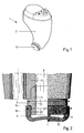
- fig. 1 shows an all-in-the-ear hearing aid with protection element according to a first embodiment of the invention,
- fig. 2 shows, on a larger scale and partly in plane section through the sound conduction end, a mounted protection element according to the invention,
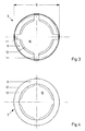
- fig. 3 shows the filter element itself seen from the outer side,
- fig. 4 shows the filter element itself seen from the inner side,
- fig. 5 shows a dispenser with new filters,
- fig. 6 shows a plane section in the dispenser in fig. 5, seen in the direction VI-VI, and
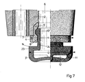
- fig. 7 shows an all-in-the-ear hearing aid with protection element according to a second embodiment of the invention.
- In Fig. 1 of the drawing is seen a normal all-in-the-ear hearing aid 1 which comprises a housing of thermoplastic material which contains the whole of the electronic circuit, sound receiver, sound transducer plus battery and regulation elements. In the
tip 2 of the housing there is a sound conduction end with a protection element comprising afilter element 3, so that earwax cannot penetrate in through the sound conduction end, which via a short sound channel leads to the sound transducer. - In fig. 2 is seen a plane section on a larger scale through the
sound conduction channel 6 in thehousing 2, the bottom of saidchannel 6 being terminated with asound conduction tube 5 of plastic or steel. In the tip end of thehearing aid housing 2 can also be provided a ventilation opening, as shown in the left side of fig. 2. - The
sound conduction tube 5 will normally be axis symmetrical, as shown in fig. 2, and be secured in thehousing 2 of the hearing aid by means of adhesive, crimping or by other means. Thetube 5 has afree end 4 which extends outside the housing, and the part which lies outside of the housing is provided with acircular collar 7 which abuts against the outer side of thehousing 2. Thefree end 4 of the tube part is provided with a projectingflange 8 with chamfered or rounded edges, as shown. Thefilter element 3, which is in the form of a cap which can be snapped down over the free end of the sound conduction tube, has acircular flange 13 around its inside edge. For reasons of the resilient construction of thefilter element 3, saidcircular flange 13 can be snapped down over the projectingflange 8 on thetube 5. Thefilter element 3 has an external diameter D which is greater than the external diameter T of thesound conduction tube 5, so that there arises an annular, free andsharp edge 14 with an engagement surface in which a tool for the removal of thefilter element 3 can gain a hold. - In figs. 3 and 4 is seen the
actual filter element 3, which is a one-piece plastic part and comprises an annular andcylindrical part 9, aplane masking part 10 and a number ofbridge parts 11 between said two parts. There thus arises a number ofsound conduction openings 12, partly concealed by the maskingpart 10 which covers theopenings 12 so that wax and the like cannot directly penetrate through the openings and into thesound conduction tube 5, and thereby into thesound conduction channel 6. - In figs. 5 and 6 of the drawing is seen a tool designed as a
dispenser 22 and for use in the replacement offilter elements 3 according to the invention. The dispenser consists of threeparts part 15, which constitutues a support part for the remaining parts, also comprises a number of mouldedfilter elements 3 which are moulded in one with thesupport part 15, and which at the bridge-like deadheads 18 are firmly connected to thesupport part 15. Thedeadheads 18 narrow down towards the filter elements, so that said elements can be broken free of the deadheads in such a manner that the deadheads remain sitting firmly on thepart 15. Below the filter elements, which in the example shown are disposed in a ring in the dispenser, is provided abottomplate 16 which serves as underlayer and support when a filter is being mounted by the hearing aid's sound conduction tube being pressed down into the filter element. In addition, the dispenser comprises atransparent cover 17 with anopening 25. Thisopening 25 can be turned into place over an unused filter when the filter is to be secured to a hearing aid. Acentral part 24 of thesupport part 15 is formed as achamber 21 which is closed by thebottomplate 16. The chamber has a centrally disposedopening 20 with a clearance or diameter d which is smaller than the outer diameter D of the filter element. Preferably, d is equal to t, see fig. 2. Thechamber 21 is intended for the collection of used filter elements. 19 indicates an empty place from which the filter element has been removed. Thecentral part 24 will preferably be of a slight funnel shape in towards thecentral opening 20. - When a hearing aid 1 with
filter element 3 is pressed down against theopening 20, thefilter element 3 will be able to be fed in through theopening 20 and into thechamber 21 with a slight click. When the hearing aid is removed again, theedge 14 of the filter element will abut against the under edge of theopening 20, and the filter element will be removed and remain in thechamber 21. - It will be obvious to those skilled in the art that the configuration of the
sound conduction tube 5 and thefilter element 3 shown in the drawing is only an example of how these can be configured. Said parts can be designed in many other ways without deviating from basic concept of the invention. Fig. 7 of the drawing shows an example of an embodiment in which thefilter element 3′ is snapped firmly inside thesound conduction tube 5′. The same reference figures have been used for all parts as in fig. 2, and those parts which are configured differently are indicated with the figures 3′, 5′, 8′ and 13′. The inside of thesound tube 5′ has a recess which prevents thefilter element 3′ from being pressed too far inside the tube. The filter element 3′ has an annularbottom part 23 which goes over to atubular part 24 which is arranged for insertion into the sound conduction tube, said tube having an internal annual groove for theflange 13′ on thefilter unit 3′. Thisfilter unit 3′ is mounted and removed in the same manner as described earlier in connection with the first embodiment. - Similarly, the dispenser shown in figs. 5 and 6 is solely an example of how such a tool can be arranged for use in the exchanging of filter elements.
- In the examples shown in the drawing, the filter element is of the following dimensions: D = 4.2 mm and the greatest height of the filter element is 1.45 mm. The sound conduction tube has an axial length of 2.65 mm and t = 3.9 mm.
Claims (10)
Applications Claiming Priority (2)
| Application Number | Priority Date | Filing Date | Title |
|---|---|---|---|
| DK5384/87 | 1987-10-14 | ||
| DK538487A DK157647C (en) | 1987-10-14 | 1987-10-14 | PROTECTION ORGANIZATION FOR ALT-I-HEARED HEARING AND TOOL FOR USE IN REPLACEMENT OF IT |
Publications (3)
| Publication Number | Publication Date |
|---|---|
| EP0312517A2 true EP0312517A2 (en) | 1989-04-19 |
| EP0312517A3 EP0312517A3 (en) | 1992-07-08 |
| EP0312517B1 EP0312517B1 (en) | 1994-08-31 |
Family
ID=8142016
Family Applications (1)
| Application Number | Title | Priority Date | Filing Date |
|---|---|---|---|
| EP88850340A Expired - Lifetime EP0312517B1 (en) | 1987-10-14 | 1988-10-12 | Dispenser for hearing aid wax filter elements |
Country Status (4)
| Country | Link |
|---|---|
| US (1) | US4984277A (en) |
| EP (1) | EP0312517B1 (en) |
| DE (1) | DE3851292T2 (en) |
| DK (1) | DK157647C (en) |
Cited By (13)
| Publication number | Priority date | Publication date | Assignee | Title |
|---|---|---|---|---|
| WO1990002471A1 (en) * | 1988-08-26 | 1990-03-08 | Tøpholm & Westermann APS | Cerumen trap for hearing aids |
| EP0627155A4 (en) * | 1992-12-21 | 1995-02-22 | Donald E K Campbell | Cerumen barrier for hearing instruments. |
| WO1999007182A3 (en) * | 1997-07-29 | 1999-04-22 | Decibel Instr Inc | Acoustic coupler |
| WO2003067926A3 (en) * | 2002-02-07 | 2003-12-24 | Oticon As | Filter manipulator, filter, holder for a number of filter manipulators, and system comprising a filter manipulator and a holder for a filter manipulator |
| EP1448015A1 (en) * | 2003-02-14 | 2004-08-18 | GN ReSound A/S | An adaptor for mounting a sound tube in an earpiece |
| EP1562398A3 (en) * | 1998-07-10 | 2005-08-17 | Widex A/S | An ear wax guard for an in-the-ear hearing aid and a means for use at insertion and removal hereof |
| DE102006008044B3 (en) * | 2006-02-21 | 2007-05-10 | Siemens Audiologische Technik Gmbh | In-the-ear hearing aid, has ventilation channel with openings in first- and second-housing zones |
| DE102008038213B3 (en) * | 2008-08-18 | 2009-10-29 | Siemens Medical Instruments Pte. Ltd. | Hearing aid with a transformer protection device |
| EP2645742A1 (en) * | 2012-03-30 | 2013-10-02 | Oticon A/S | Earwax filter and handing tool for such filter |
| EP2930948A1 (en) * | 2014-04-10 | 2015-10-14 | GN Resound A/S | Hearing aid |
| US9578430B2 (en) | 2014-04-10 | 2017-02-21 | Gn Hearing A/S | Hearing aid |
| WO2019105522A1 (en) * | 2017-11-28 | 2019-06-06 | Sonova Ag | Cerumen filter applicator |
| EP4475562A1 (en) * | 2023-06-06 | 2024-12-11 | Constanton GmbH | Hearing aid maintenance kit |
Families Citing this family (101)
| Publication number | Priority date | Publication date | Assignee | Title |
|---|---|---|---|---|
| JPH07501673A (en) * | 1991-12-09 | 1995-02-16 | オリベイラ,ロバート,ジェイ. | Earwax filter for hearing aids |
| US5748743A (en) * | 1994-08-01 | 1998-05-05 | Ear Craft Technologies | Air conduction hearing device |
| US5819745A (en) * | 1994-08-16 | 1998-10-13 | House Ear Institute | Pressure-regulating ear plug |
| US5712918A (en) * | 1995-01-27 | 1998-01-27 | Beltone Electronics Corporation | Press-fit ear wax barrier |
| US5982908A (en) * | 1997-12-22 | 1999-11-09 | Bauman; Natan | Ear wax collection device for a hearing aid |
| US7046239B2 (en) * | 2000-01-25 | 2006-05-16 | Minolta Co., Ltd. | Electronic apparatus |
| US6540045B1 (en) * | 2000-06-30 | 2003-04-01 | Phonak Ag | Method for manufacturing an ear device and ear device |
| US7625335B2 (en) | 2000-08-25 | 2009-12-01 | 3Shape Aps | Method and apparatus for three-dimensional optical scanning of interior surfaces |
| DK1368986T3 (en) * | 2001-03-02 | 2012-02-27 | 3Shape As | Method of modeling custom made earpieces |
| USD480386S1 (en) | 2002-05-06 | 2003-10-07 | Newlands Technology Limited | Sound bug reproducing device |
| US8457336B2 (en) * | 2004-02-05 | 2013-06-04 | Insound Medical, Inc. | Contamination resistant ports for hearing devices |
| US7471800B2 (en) * | 2004-03-29 | 2008-12-30 | In'tech Industries, Inc. | Wax barrier system |
| US7162323B2 (en) * | 2004-04-05 | 2007-01-09 | Hearing Aid Express, Inc. | Decentralized method for manufacturing hearing aid devices |
| WO2006060486A2 (en) * | 2004-12-01 | 2006-06-08 | Synygis, Llc | Acoustically tailored hearing aid and method of manufacture |
| US7720243B2 (en) * | 2006-10-12 | 2010-05-18 | Synygis, Llc | Acoustic enhancement for behind the ear communication devices |
| DE202007016881U1 (en) * | 2007-12-03 | 2009-04-09 | Sennheiser Electronic Gmbh & Co. Kg | receiver |
| USD738862S1 (en) | 2013-10-25 | 2015-09-15 | Aliphcom | Ear piece |
| USD726694S1 (en) * | 2013-10-25 | 2015-04-14 | Aliphcom | Ear bud |
| US10122421B2 (en) | 2015-08-29 | 2018-11-06 | Bragi GmbH | Multimodal communication system using induction and radio and method |
| US9905088B2 (en) | 2015-08-29 | 2018-02-27 | Bragi GmbH | Responsive visual communication system and method |
| US9972895B2 (en) | 2015-08-29 | 2018-05-15 | Bragi GmbH | Antenna for use in a wearable device |
| US9949013B2 (en) | 2015-08-29 | 2018-04-17 | Bragi GmbH | Near field gesture control system and method |
| US9843853B2 (en) | 2015-08-29 | 2017-12-12 | Bragi GmbH | Power control for battery powered personal area network device system and method |
| US9854372B2 (en) | 2015-08-29 | 2017-12-26 | Bragi GmbH | Production line PCB serial programming and testing method and system |
| US9949008B2 (en) | 2015-08-29 | 2018-04-17 | Bragi GmbH | Reproduction of ambient environmental sound for acoustic transparency of ear canal device system and method |
| US9866941B2 (en) | 2015-10-20 | 2018-01-09 | Bragi GmbH | Multi-point multiple sensor array for data sensing and processing system and method |
| US10104458B2 (en) | 2015-10-20 | 2018-10-16 | Bragi GmbH | Enhanced biometric control systems for detection of emergency events system and method |
| US9980189B2 (en) | 2015-10-20 | 2018-05-22 | Bragi GmbH | Diversity bluetooth system and method |
| US10506322B2 (en) | 2015-10-20 | 2019-12-10 | Bragi GmbH | Wearable device onboard applications system and method |
| US9980033B2 (en) | 2015-12-21 | 2018-05-22 | Bragi GmbH | Microphone natural speech capture voice dictation system and method |
| US9939891B2 (en) | 2015-12-21 | 2018-04-10 | Bragi GmbH | Voice dictation systems using earpiece microphone system and method |
| US10085091B2 (en) | 2016-02-09 | 2018-09-25 | Bragi GmbH | Ambient volume modification through environmental microphone feedback loop system and method |
| US10085082B2 (en) | 2016-03-11 | 2018-09-25 | Bragi GmbH | Earpiece with GPS receiver |
| US10045116B2 (en) | 2016-03-14 | 2018-08-07 | Bragi GmbH | Explosive sound pressure level active noise cancellation utilizing completely wireless earpieces system and method |
| US10052065B2 (en) | 2016-03-23 | 2018-08-21 | Bragi GmbH | Earpiece life monitor with capability of automatic notification system and method |
| USD823835S1 (en) | 2016-04-07 | 2018-07-24 | Bragi GmbH | Earphone |
| US10015579B2 (en) | 2016-04-08 | 2018-07-03 | Bragi GmbH | Audio accelerometric feedback through bilateral ear worn device system and method |
| US10013542B2 (en) | 2016-04-28 | 2018-07-03 | Bragi GmbH | Biometric interface system and method |
| USD836089S1 (en) | 2016-05-06 | 2018-12-18 | Bragi GmbH | Headphone |
| USD824371S1 (en) * | 2016-05-06 | 2018-07-31 | Bragi GmbH | Headphone |
| US10582328B2 (en) | 2016-07-06 | 2020-03-03 | Bragi GmbH | Audio response based on user worn microphones to direct or adapt program responses system and method |
| US10888039B2 (en) | 2016-07-06 | 2021-01-05 | Bragi GmbH | Shielded case for wireless earpieces |
| US11085871B2 (en) | 2016-07-06 | 2021-08-10 | Bragi GmbH | Optical vibration detection system and method |
| US10216474B2 (en) | 2016-07-06 | 2019-02-26 | Bragi GmbH | Variable computing engine for interactive media based upon user biometrics |
| US10201309B2 (en) | 2016-07-06 | 2019-02-12 | Bragi GmbH | Detection of physiological data using radar/lidar of wireless earpieces |
| US10555700B2 (en) | 2016-07-06 | 2020-02-11 | Bragi GmbH | Combined optical sensor for audio and pulse oximetry system and method |
| US10045110B2 (en) | 2016-07-06 | 2018-08-07 | Bragi GmbH | Selective sound field environment processing system and method |
| US10621583B2 (en) | 2016-07-07 | 2020-04-14 | Bragi GmbH | Wearable earpiece multifactorial biometric analysis system and method |
| US10158934B2 (en) | 2016-07-07 | 2018-12-18 | Bragi GmbH | Case for multiple earpiece pairs |
| US10516930B2 (en) | 2016-07-07 | 2019-12-24 | Bragi GmbH | Comparative analysis of sensors to control power status for wireless earpieces |
| US10165350B2 (en) | 2016-07-07 | 2018-12-25 | Bragi GmbH | Earpiece with app environment |
| US10587943B2 (en) | 2016-07-09 | 2020-03-10 | Bragi GmbH | Earpiece with wirelessly recharging battery |
| US10397686B2 (en) | 2016-08-15 | 2019-08-27 | Bragi GmbH | Detection of movement adjacent an earpiece device |
| US10977348B2 (en) | 2016-08-24 | 2021-04-13 | Bragi GmbH | Digital signature using phonometry and compiled biometric data system and method |
| US10104464B2 (en) | 2016-08-25 | 2018-10-16 | Bragi GmbH | Wireless earpiece and smart glasses system and method |
| US10409091B2 (en) | 2016-08-25 | 2019-09-10 | Bragi GmbH | Wearable with lenses |
| US10887679B2 (en) | 2016-08-26 | 2021-01-05 | Bragi GmbH | Earpiece for audiograms |
| US11086593B2 (en) | 2016-08-26 | 2021-08-10 | Bragi GmbH | Voice assistant for wireless earpieces |
| US11200026B2 (en) | 2016-08-26 | 2021-12-14 | Bragi GmbH | Wireless earpiece with a passive virtual assistant |
| US10313779B2 (en) | 2016-08-26 | 2019-06-04 | Bragi GmbH | Voice assistant system for wireless earpieces |
| US10200780B2 (en) | 2016-08-29 | 2019-02-05 | Bragi GmbH | Method and apparatus for conveying battery life of wireless earpiece |
| US11490858B2 (en) | 2016-08-31 | 2022-11-08 | Bragi GmbH | Disposable sensor array wearable device sleeve system and method |
| USD822645S1 (en) | 2016-09-03 | 2018-07-10 | Bragi GmbH | Headphone |
| US10598506B2 (en) | 2016-09-12 | 2020-03-24 | Bragi GmbH | Audio navigation using short range bilateral earpieces |
| US10580282B2 (en) | 2016-09-12 | 2020-03-03 | Bragi GmbH | Ear based contextual environment and biometric pattern recognition system and method |
| US10852829B2 (en) | 2016-09-13 | 2020-12-01 | Bragi GmbH | Measurement of facial muscle EMG potentials for predictive analysis using a smart wearable system and method |
| US11283742B2 (en) | 2016-09-27 | 2022-03-22 | Bragi GmbH | Audio-based social media platform |
| US10460095B2 (en) | 2016-09-30 | 2019-10-29 | Bragi GmbH | Earpiece with biometric identifiers |
| US10049184B2 (en) | 2016-10-07 | 2018-08-14 | Bragi GmbH | Software application transmission via body interface using a wearable device in conjunction with removable body sensor arrays system and method |
| US10771877B2 (en) | 2016-10-31 | 2020-09-08 | Bragi GmbH | Dual earpieces for same ear |
| US10698983B2 (en) | 2016-10-31 | 2020-06-30 | Bragi GmbH | Wireless earpiece with a medical engine |
| US10942701B2 (en) | 2016-10-31 | 2021-03-09 | Bragi GmbH | Input and edit functions utilizing accelerometer based earpiece movement system and method |
| US10455313B2 (en) | 2016-10-31 | 2019-10-22 | Bragi GmbH | Wireless earpiece with force feedback |
| US10617297B2 (en) | 2016-11-02 | 2020-04-14 | Bragi GmbH | Earpiece with in-ear electrodes |
| US10117604B2 (en) | 2016-11-02 | 2018-11-06 | Bragi GmbH | 3D sound positioning with distributed sensors |
| US10821361B2 (en) | 2016-11-03 | 2020-11-03 | Bragi GmbH | Gaming with earpiece 3D audio |
| US10062373B2 (en) | 2016-11-03 | 2018-08-28 | Bragi GmbH | Selective audio isolation from body generated sound system and method |
| US10205814B2 (en) | 2016-11-03 | 2019-02-12 | Bragi GmbH | Wireless earpiece with walkie-talkie functionality |
| US10225638B2 (en) | 2016-11-03 | 2019-03-05 | Bragi GmbH | Ear piece with pseudolite connectivity |
| US10045112B2 (en) | 2016-11-04 | 2018-08-07 | Bragi GmbH | Earpiece with added ambient environment |
| US10058282B2 (en) | 2016-11-04 | 2018-08-28 | Bragi GmbH | Manual operation assistance with earpiece with 3D sound cues |
| US10045117B2 (en) | 2016-11-04 | 2018-08-07 | Bragi GmbH | Earpiece with modified ambient environment over-ride function |
| US10063957B2 (en) | 2016-11-04 | 2018-08-28 | Bragi GmbH | Earpiece with source selection within ambient environment |
| US10506327B2 (en) | 2016-12-27 | 2019-12-10 | Bragi GmbH | Ambient environmental sound field manipulation based on user defined voice and audio recognition pattern analysis system and method |
| US10405081B2 (en) | 2017-02-08 | 2019-09-03 | Bragi GmbH | Intelligent wireless headset system |
| US10582290B2 (en) | 2017-02-21 | 2020-03-03 | Bragi GmbH | Earpiece with tap functionality |
| US10771881B2 (en) | 2017-02-27 | 2020-09-08 | Bragi GmbH | Earpiece with audio 3D menu |
| US10575086B2 (en) | 2017-03-22 | 2020-02-25 | Bragi GmbH | System and method for sharing wireless earpieces |
| US11380430B2 (en) | 2017-03-22 | 2022-07-05 | Bragi GmbH | System and method for populating electronic medical records with wireless earpieces |
| US11694771B2 (en) | 2017-03-22 | 2023-07-04 | Bragi GmbH | System and method for populating electronic health records with wireless earpieces |
| US11544104B2 (en) | 2017-03-22 | 2023-01-03 | Bragi GmbH | Load sharing between wireless earpieces |
| US10708699B2 (en) | 2017-05-03 | 2020-07-07 | Bragi GmbH | Hearing aid with added functionality |
| US11116415B2 (en) | 2017-06-07 | 2021-09-14 | Bragi GmbH | Use of body-worn radar for biometric measurements, contextual awareness and identification |
| US11013445B2 (en) | 2017-06-08 | 2021-05-25 | Bragi GmbH | Wireless earpiece with transcranial stimulation |
| US10344960B2 (en) | 2017-09-19 | 2019-07-09 | Bragi GmbH | Wireless earpiece controlled medical headlight |
| US11272367B2 (en) | 2017-09-20 | 2022-03-08 | Bragi GmbH | Wireless earpieces for hub communications |
| US11140498B2 (en) | 2017-10-17 | 2021-10-05 | Eargo, Inc. | Wax management system |
| DE102018125655A1 (en) | 2017-10-17 | 2019-04-18 | Eargo, Inc. | Hand-removable, clip-on earwax protectors |
| US11014125B2 (en) | 2017-10-17 | 2021-05-25 | Eargo, Inc. | Hand removable, clip on wax guards |
| USD853359S1 (en) * | 2018-01-25 | 2019-07-09 | Yong Guo | Housing for high-fidelity earbud |
| USD972146S1 (en) * | 2021-05-19 | 2022-12-06 | Ear Labs Ab | Ear plug |
Family Cites Families (17)
| Publication number | Priority date | Publication date | Assignee | Title |
|---|---|---|---|---|
| BE567740A (en) * | 1957-05-16 | |||
| US3197577A (en) * | 1964-09-24 | 1965-07-27 | Dabiberg Electronics Inc | Wax retarder baffle for hearing aids |
| US3374318A (en) * | 1965-04-01 | 1968-03-19 | Dahlberg Electronics | Wax guard for hearing aids |
| US3408461A (en) * | 1965-05-28 | 1968-10-29 | Royal Industries | Hearing aid |
| US3414685A (en) * | 1965-09-23 | 1968-12-03 | Dahlberg Electronics | In-the-ear hearing aid |
| US3433351A (en) * | 1967-09-15 | 1969-03-18 | Mallory & Co Inc P R | Circular dispensing device for batteries |
| US3633792A (en) * | 1969-11-17 | 1972-01-11 | Beltone Electronics Corp | Small article dispenser |
| GB1420924A (en) * | 1971-11-30 | 1976-01-14 | Protim & Gallwey Ltd | Damp-proofing |
| CA1032511A (en) * | 1974-10-15 | 1978-06-06 | Robert E. Brindley | Battery dispenser |
| JPH0312000Y2 (en) * | 1981-04-20 | 1991-03-22 | ||
| US4399914A (en) * | 1982-04-16 | 1983-08-23 | Triad Corporation | Pilfer resistant container |
| US4706815A (en) * | 1982-08-23 | 1987-11-17 | American Home Products Corporation | Dispensing container for triphasic |
| FR2543431A1 (en) * | 1983-03-30 | 1984-10-05 | Cafa | HEARING AID SUCH AS A PROSTHESIS |
| CA1221315A (en) * | 1984-10-19 | 1987-05-05 | William J. Gastmeier | Hearing aid wax guard |
| DE8518681U1 (en) * | 1985-06-27 | 1986-06-12 | Siemens AG, 1000 Berlin und 8000 München | Hearing aid |
| DE3540579A1 (en) * | 1985-11-15 | 1987-05-27 | Toepholm & Westermann | IN-EAR HOERING DEVICE |
| US4716985A (en) * | 1986-05-16 | 1988-01-05 | Siemens Aktiengesellschaft | In-the-ear hearing aid |
-
1987
- 1987-10-14 DK DK538487A patent/DK157647C/en not_active IP Right Cessation
-
1988
- 1988-10-11 US US07/255,717 patent/US4984277A/en not_active Expired - Lifetime
- 1988-10-12 EP EP88850340A patent/EP0312517B1/en not_active Expired - Lifetime
- 1988-10-12 DE DE3851292T patent/DE3851292T2/en not_active Expired - Lifetime
Cited By (22)
| Publication number | Priority date | Publication date | Assignee | Title |
|---|---|---|---|---|
| WO1990002471A1 (en) * | 1988-08-26 | 1990-03-08 | Tøpholm & Westermann APS | Cerumen trap for hearing aids |
| EP0627155A4 (en) * | 1992-12-21 | 1995-02-22 | Donald E K Campbell | Cerumen barrier for hearing instruments. |
| WO1999007182A3 (en) * | 1997-07-29 | 1999-04-22 | Decibel Instr Inc | Acoustic coupler |
| EP1562398A3 (en) * | 1998-07-10 | 2005-08-17 | Widex A/S | An ear wax guard for an in-the-ear hearing aid and a means for use at insertion and removal hereof |
| WO2003067926A3 (en) * | 2002-02-07 | 2003-12-24 | Oticon As | Filter manipulator, filter, holder for a number of filter manipulators, and system comprising a filter manipulator and a holder for a filter manipulator |
| US7292701B2 (en) | 2002-02-07 | 2007-11-06 | Oticon A/S | Filter manipulator, filter, holder for a number of filter manipulators, and system comprising a filter manipulator and a holder for a filter manipulator |
| EP1448015A1 (en) * | 2003-02-14 | 2004-08-18 | GN ReSound A/S | An adaptor for mounting a sound tube in an earpiece |
| EP2661098A1 (en) * | 2003-02-14 | 2013-11-06 | GN Resound A/S | An adaptor for mounting a sound tube in an earpiece |
| DE102006008044B3 (en) * | 2006-02-21 | 2007-05-10 | Siemens Audiologische Technik Gmbh | In-the-ear hearing aid, has ventilation channel with openings in first- and second-housing zones |
| US7983434B2 (en) | 2006-02-21 | 2011-07-19 | Siemens Audiologische Technik Gmbh | In-the ear hearing aid device with a vent |
| EP2157815A1 (en) | 2008-08-18 | 2010-02-24 | Siemens Medical Instruments Pte. Ltd. | Hearing aid with a converter protection device |
| DE102008038213B8 (en) * | 2008-08-18 | 2010-02-11 | Siemens Medical Instruments Pte. Ltd. | Hearing aid with a transformer protection device |
| US8233649B2 (en) | 2008-08-18 | 2012-07-31 | Siemens Medical Instruments Pte. Ltd. | Hearing aid device with a transducer protection facility |
| DE102008038213B3 (en) * | 2008-08-18 | 2009-10-29 | Siemens Medical Instruments Pte. Ltd. | Hearing aid with a transformer protection device |
| EP2645742A1 (en) * | 2012-03-30 | 2013-10-02 | Oticon A/S | Earwax filter and handing tool for such filter |
| US8824714B2 (en) | 2012-03-30 | 2014-09-02 | Oticon A/S | Earwax filter, handing tool and dispenser for such filter |
| EP2930948A1 (en) * | 2014-04-10 | 2015-10-14 | GN Resound A/S | Hearing aid |
| US9578430B2 (en) | 2014-04-10 | 2017-02-21 | Gn Hearing A/S | Hearing aid |
| WO2019105522A1 (en) * | 2017-11-28 | 2019-06-06 | Sonova Ag | Cerumen filter applicator |
| US11190888B2 (en) | 2017-11-28 | 2021-11-30 | Sonova Ag | Cerumen filter applicator |
| EP4475562A1 (en) * | 2023-06-06 | 2024-12-11 | Constanton GmbH | Hearing aid maintenance kit |
| WO2024251845A1 (en) * | 2023-06-06 | 2024-12-12 | Constanton Gmbh | Hearing aid maintenance set |
Also Published As
| Publication number | Publication date |
|---|---|
| DK538487A (en) | 1989-04-15 |
| EP0312517A3 (en) | 1992-07-08 |
| DK538487D0 (en) | 1987-10-14 |
| DK157647B (en) | 1990-01-29 |
| US4984277A (en) | 1991-01-08 |
| DE3851292T2 (en) | 1995-02-09 |
| DE3851292D1 (en) | 1994-10-06 |
| DK157647C (en) | 1990-07-09 |
| EP0312517B1 (en) | 1994-08-31 |
Similar Documents
| Publication | Publication Date | Title |
|---|---|---|
| US4984277A (en) | Protection element for all-in-the-ear hearing aid | |
| US5131128A (en) | Protection element for all-in-the-ear hearing aid and tool for use in the replacement hereof | |
| US6795562B1 (en) | Ear wax guard for an in-the-ear hearing aid and a means for use at insertion and removal hereof | |
| US4879750A (en) | Hearing aid with cerumen trapping gap | |
| EP0724377B1 (en) | Hearing aid with a press-fit ear wax barrier | |
| US8867768B2 (en) | Earpiece assembly with foil clip | |
| US7471800B2 (en) | Wax barrier system | |
| US4815138A (en) | In-the-ear hearing-aid with pivotable inner and outer sections | |
| GB2155276A (en) | Hearing aid ear piece with wax guard | |
| US3374318A (en) | Wax guard for hearing aids | |
| JPS61230499A (en) | Hearing aid | |
| AU8409798A (en) | Behind the ear hearing aid system | |
| WO2015010717A1 (en) | A rechargable hearing device and a battery charger for charging the hearing device | |
| JPS61131700A (en) | Hearing aid | |
| US20170347212A1 (en) | Retaining cap for a standard earpiece and standard earpiece | |
| WO1997009864A1 (en) | Hearing aid with wax guard | |
| CN107079227B (en) | Transducer Protection Systems, Hearing Devices, and Use of Transducer Protection Systems | |
| CN111557099B (en) | Earwax filter applicator | |
| DE102014200605A1 (en) | Dome with cerumen protection | |
| EP4061013B1 (en) | Completely-in-canal hearing aid | |
| JPH1198598A (en) | Hearing aid | |
| EP1763284B1 (en) | Behind the ear hearing system | |
| US20250386156A1 (en) | Ear wearing sound output device and insertion member | |
| EP4550827A1 (en) | Ear tip with filtering element for a hearing device or for a hearing device part | |
| JP2005268990A (en) | Fall-off preventing tool |
Legal Events
| Date | Code | Title | Description |
|---|---|---|---|
| PUAI | Public reference made under article 153(3) epc to a published international application that has entered the european phase |
Free format text: ORIGINAL CODE: 0009012 |
|
| AK | Designated contracting states |
Kind code of ref document: A2 Designated state(s): CH DE FR GB IT LI NL SE |
|
| PUAL | Search report despatched |
Free format text: ORIGINAL CODE: 0009013 |
|
| AK | Designated contracting states |
Kind code of ref document: A3 Designated state(s): CH DE FR GB IT LI NL SE |
|
| 17P | Request for examination filed |
Effective date: 19921207 |
|
| 17Q | First examination report despatched |
Effective date: 19930427 |
|
| RAP1 | Party data changed (applicant data changed or rights of an application transferred) |
Owner name: GN DANAVOX A/S |
|
| GRAA | (expected) grant |
Free format text: ORIGINAL CODE: 0009210 |
|
| AK | Designated contracting states |
Kind code of ref document: B1 Designated state(s): CH DE FR GB IT LI NL SE |
|
| PG25 | Lapsed in a contracting state [announced via postgrant information from national office to epo] |
Ref country code: IT Free format text: LAPSE BECAUSE OF FAILURE TO SUBMIT A TRANSLATION OF THE DESCRIPTION OR TO PAY THE FEE WITHIN THE PRE;WARNING: LAPSES OF ITALIAN PATENTS WITH EFFECTIVE DATE BEFORE 2007 MAY HAVE OCCURRED AT ANY TIME BEFORE 2007. THE CORRECT EFFECTIVE DATE MAY BE DIFFERENT FROM THE ONE RECORDED.SCRIBED TIME-LIMIT Effective date: 19940831 Ref country code: NL Effective date: 19940831 |
|
| REF | Corresponds to: |
Ref document number: 3851292 Country of ref document: DE Date of ref document: 19941006 |
|
| ET | Fr: translation filed | ||
| PG25 | Lapsed in a contracting state [announced via postgrant information from national office to epo] |
Ref country code: SE Effective date: 19941130 |
|
| NLV1 | Nl: lapsed or annulled due to failure to fulfill the requirements of art. 29p and 29m of the patents act | ||
| PLBE | No opposition filed within time limit |
Free format text: ORIGINAL CODE: 0009261 |
|
| STAA | Information on the status of an ep patent application or granted ep patent |
Free format text: STATUS: NO OPPOSITION FILED WITHIN TIME LIMIT |
|
| 26N | No opposition filed | ||
| REG | Reference to a national code |
Ref country code: GB Ref legal event code: IF02 |
|
| REG | Reference to a national code |
Ref country code: CH Ref legal event code: NV Representative=s name: DR. LUSUARDI AG |
|
| REG | Reference to a national code |
Ref country code: CH Ref legal event code: PFA Owner name: GN DANAVOX A/S Free format text: GN DANAVOX A/S#MARKAERVEJ 2A POSTBOX 224#TAASTRUP (DK) -TRANSFER TO- GN DANAVOX A/S#MARKAERVEJ 2A POSTBOX 224#TAASTRUP (DK) |
|
| PGFP | Annual fee paid to national office [announced via postgrant information from national office to epo] |
Ref country code: DE Payment date: 20071119 Year of fee payment: 20 |
|
| PGFP | Annual fee paid to national office [announced via postgrant information from national office to epo] |
Ref country code: CH Payment date: 20071025 Year of fee payment: 20 |
|
| PGFP | Annual fee paid to national office [announced via postgrant information from national office to epo] |
Ref country code: GB Payment date: 20071019 Year of fee payment: 20 Ref country code: FR Payment date: 20071031 Year of fee payment: 20 |
|
| REG | Reference to a national code |
Ref country code: CH Ref legal event code: PL |
|
| REG | Reference to a national code |
Ref country code: GB Ref legal event code: PE20 Expiry date: 20081011 |
|
| PG25 | Lapsed in a contracting state [announced via postgrant information from national office to epo] |
Ref country code: GB Free format text: LAPSE BECAUSE OF EXPIRATION OF PROTECTION Effective date: 20081011 |