EP0312772A2 - Imprimante par impact - Google Patents
Imprimante par impact Download PDFInfo
- Publication number
- EP0312772A2 EP0312772A2 EP88115159A EP88115159A EP0312772A2 EP 0312772 A2 EP0312772 A2 EP 0312772A2 EP 88115159 A EP88115159 A EP 88115159A EP 88115159 A EP88115159 A EP 88115159A EP 0312772 A2 EP0312772 A2 EP 0312772A2
- Authority
- EP
- European Patent Office
- Prior art keywords
- hammer
- printing
- platen
- detecting
- conformity
- Prior art date
- Legal status (The legal status is an assumption and is not a legal conclusion. Google has not performed a legal analysis and makes no representation as to the accuracy of the status listed.)
- Granted
Links
- 238000001514 detection method Methods 0.000 claims abstract description 6
- 239000013013 elastic material Substances 0.000 claims description 2
- 230000003116 impacting effect Effects 0.000 claims 3
- 230000000694 effects Effects 0.000 description 6
- 230000006835 compression Effects 0.000 description 4
- 238000007906 compression Methods 0.000 description 4
- 238000010276 construction Methods 0.000 description 3
- 230000003247 decreasing effect Effects 0.000 description 3
- 241000723353 Chrysanthemum Species 0.000 description 2
- 235000005633 Chrysanthemum balsamita Nutrition 0.000 description 2
- 238000013016 damping Methods 0.000 description 2
- 238000010586 diagram Methods 0.000 description 2
- 230000007613 environmental effect Effects 0.000 description 2
- 230000005284 excitation Effects 0.000 description 2
- 239000000696 magnetic material Substances 0.000 description 2
- 238000006243 chemical reaction Methods 0.000 description 1
- 238000006073 displacement reaction Methods 0.000 description 1
- 238000000034 method Methods 0.000 description 1
Images


Classifications
-
- B—PERFORMING OPERATIONS; TRANSPORTING
- B41—PRINTING; LINING MACHINES; TYPEWRITERS; STAMPS
- B41J—TYPEWRITERS; SELECTIVE PRINTING MECHANISMS, i.e. MECHANISMS PRINTING OTHERWISE THAN FROM A FORME; CORRECTION OF TYPOGRAPHICAL ERRORS
- B41J9/00—Hammer-impression mechanisms
- B41J9/42—Hammer-impression mechanisms with anti-rebound arrangements
-
- B—PERFORMING OPERATIONS; TRANSPORTING
- B41—PRINTING; LINING MACHINES; TYPEWRITERS; STAMPS
- B41J—TYPEWRITERS; SELECTIVE PRINTING MECHANISMS, i.e. MECHANISMS PRINTING OTHERWISE THAN FROM A FORME; CORRECTION OF TYPOGRAPHICAL ERRORS
- B41J9/00—Hammer-impression mechanisms
- B41J9/44—Control for hammer-impression mechanisms
- B41J9/50—Control for hammer-impression mechanisms for compensating for the variations of printer drive conditions, e.g. for compensating for the variation of temperature or current supply
-
- G—PHYSICS
- G01—MEASURING; TESTING
- G01N—INVESTIGATING OR ANALYSING MATERIALS BY DETERMINING THEIR CHEMICAL OR PHYSICAL PROPERTIES
- G01N2203/00—Investigating strength properties of solid materials by application of mechanical stress
- G01N2203/0058—Kind of property studied
- G01N2203/0076—Hardness, compressibility or resistance to crushing
- G01N2203/0083—Rebound strike or reflected energy
Definitions
- This invention relates to an impact type printer using, for example, a daisy wheel or the like to effect printing.
- the impact type printer system has the merit that a high quality of print is obtained, while it suffers from the demerit that the moise during printing is great.
- One of the causes of this noise is the impact sound produced when the printing hammer is returned to the standby position after printing and strikes against a stopper, and as a method of decreasing such sound, it is known from U.S. Patent No. 4,744,684, etc. to effect the second power supply to the solenoid before the printing hammer strikes against the stopper, thereby imparting a damping force to the hammer.
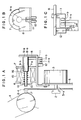
- the reference numeral 1 designates a platen and the reference numeral 2 denotes a type wheel.
- the type wheel 2 is mounted on the shaft 3-a of a motor 3 and is rotated by rotation of the motor 3, and a type 2-a to be printed is carried to between a printing hammer 9 which will be described later and the platen 1.
- the motor 3 is fixed to a carriage 5.
- a hammer base 8 is attached to the carriage 5, and a hammer mechanism portion is provided on the hammer base 8.
- This hammer mechanism portion comprises a yoke 6, a support frame 7, a printing hammer 9, a bearing 10, a coil unit 15, a compression coil spring 16, etc.
- the printing hammer 9 comprises an armature 9-a formed of a magnetic material and a fore end portion 9-b formed of a non-magnetic material.
- the printing hammer 9 is supported by the bearing 10 and the bearing portion 7-a of the support frame 7 of the coil unit 15, and is movable in the thrust direction and is normally biased to the stopper 8-a of the hammer base 8 by the reaction force of the compression coil spring 16. That is, it is normally in its standby position.
- a slit plate 11 as shown in Figures 1B and 1C is provided on the printing hammer 9 and is reciprocally moved with the printing hammer 9.
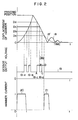
- the slit plate 11 is provided with slits 11-a and 11-b and therefore, when the printing hammer 9 effects one cycle of reciprocal movement, a sensor 12 outputs a signal 19 as shown in Figure 2.
- the curve 18 of Figure 2 graphically shows the position of the printing hammer 9 for time. That is, in the figure, the printing hammer 9 is guickly protruded with the first power supply and arrives at the printing position. When the first power supply is terminated, the printing hammer 9 is returned rearwardly by the repulsion force of the coil spring and strikes against the stopper 8-a and is vibrated several times.
- the signals 19-a and 19-b of the aforementioned signal 19 of Figure 2 are output signals during the forward movement of the printing hammer 9 from the standby position to the printing position, and the signals 19-c and 19-d are output signals during the backward movement of the printing hammer from the printing position to the standby position.
- the slit width and the slit spacing are constant and therefore, if the time interval between the signals, for example, the time interval T BD between B and D, is read, the average speed of the printing hammer 9 is the meantime can be found. Also, if the mutual positional relations between the stopper 8-a and the sensor 12 and the slit 11-a are predetermined, the position of the printing hammer 9 relative to the stopper 8-a can also be detected.
- the second power supply is effected when the printing hammer 9 has come to a suitable position during the backward movement thereof, a magnetic force produced thereby acts in the direction opposite to the direction of movement of the printing hammer 9 and therefore, the return speed of the printing hammer 9 is decreased.
- a first pulse 20 is for effecting printing, and a magnetic force is produced thereby and the printing hammer 9 is thereafter returned to the standby position by the repulsion force of the platen 1 and the force of the compression coil spring 16, and if at that time, the time interval T BD of Figure 2 is detected and a proper current value and a proper excitation time are selected thereby and the second power supply is effected to the coil unit 15 at a point of time whereat the printing hammer 9 passes through D, the printing hammer 9 is decelerated by this magnetic force and slowly strikes against the stopper 8-a. This is shown by the curve 18′ of Figure 2. Thereby the impact sound between the printing hammer 9 and the stopper 8-a is greatly reduced and thus, the noise during printing can be reduced.
- the return speed of the printing hammer 9 is detected, whereby the next protrusion speed of the printing hammer 9 is controlled. That is, generally, the platen is made of an elastic material such as rubber and when it is placed in a low temperature or when the hardening of the platen by a variation with time occurs, the repulsion coefficient thereof increases as compared with the usual case and therefore, even when printing is effected with the same printing energy, the return speed of the hammer shaft becomes high. So, the printing pressure may be changed over in conformity with the return speed detected by the sensor.
- FIG 3 is a block diagram showing the printing hammer control circuit of the printer shown in Figure 1.
- the reference numeral 23 designates a CPU for controlling the recording apparatus.
- the CPU 23 has connected thereto RAM 22 for storing recording data or the like therein and ROM 24 storing therein a printing table or the like as shown in Table 1 below.
- a timer 22 measures the time interval T BD between B and D in Figure 2 and supplies the information to the CPU 23.
- a hammer driving circuit 26 is controlled by the CPU 23 in accordance with the recording data stored in RAM 24 and the printing table in ROM 25, and drives a printing hammer 27.
- FIG 4 is a flow chart showing an example of the printer control based on the above-described construction.
- step S41 whether the flag is 0 or 1 is discriminated (step S41), and if the flag is 0, the printing hammer is driven in accordance with the printing pressure table A to effect printing (step S42). Also, if at step S41, the flag is 1, the printing pressure table B (see Table 1) is drawn out and the printing hammer is driven in accordance therewith (steps S45 and S46).
- the return speed of the printing hammer is detected as T BD by the timer, and where T BD is shorter than a preset time t0, the flag is set to 1, whereafter the printing hammer returns to the standby condition for a printing command. This state of the flag being 1 is kept until the cover switch is opened (steps S43 and S44).
- the printing pressure table B is set to a printing pressure lower than the printing pressure table A, the fact that the platen has become hardened is automatically detected and printing can be effected at a printing pressure corresponding thereto.
- the releasing of the mode is effected by the cover switch, but it is also possible to measure time by the timer and release the mode after a predetermined time has elapsed, or to count the frequency of driving of the printing hammer and release the mode when it is detected within a predetermined frequency that T BD does not become t0.
- the printing pressure is changed in conformity with the return speed of the hammer detected by detecting means and therefore, printing can be accomplished with optimum printing energy conforming to the hardness of the platen.
- the printing energy is made optimum and therefore, it does not happen that it becomes too late to effect the second power supply before the hammer strikes against the stopper.
- An impact printer has a platen, a carriage movable in parallelism to the platen, a hammer carried on the carriage, driving means for protruding the hammer toward the platen, detecting means for detecting the speed of the hammer striking against the platen and returned therefrom, and control means for changing over the speed at which the hammer is protruded toward the platen in conformity with the result of the detection of the detecting means.
Landscapes
- Impact Printers (AREA)
- Character Spaces And Line Spaces In Printers (AREA)
Applications Claiming Priority (2)
| Application Number | Priority Date | Filing Date | Title |
|---|---|---|---|
| JP239469/87 | 1987-09-22 | ||
| JP62239469A JP2603271B2 (ja) | 1987-09-22 | 1987-09-22 | インパクトプリンタ |
Publications (3)
| Publication Number | Publication Date |
|---|---|
| EP0312772A2 true EP0312772A2 (fr) | 1989-04-26 |
| EP0312772A3 EP0312772A3 (fr) | 1993-11-10 |
| EP0312772B1 EP0312772B1 (fr) | 1996-01-17 |
Family
ID=17045231
Family Applications (1)
| Application Number | Title | Priority Date | Filing Date |
|---|---|---|---|
| EP19880115159 Expired - Lifetime EP0312772B1 (fr) | 1987-09-22 | 1988-09-15 | Imprimante par impact |
Country Status (3)
| Country | Link |
|---|---|
| EP (1) | EP0312772B1 (fr) |
| JP (1) | JP2603271B2 (fr) |
| DE (1) | DE3854908T2 (fr) |
Cited By (2)
| Publication number | Priority date | Publication date | Assignee | Title |
|---|---|---|---|---|
| GB2246540A (en) * | 1990-08-03 | 1992-02-05 | Samsung Electronics Co Ltd | Anti-rebound drive circuit for a printing-hammer-solenoid |
| EP0453115A3 (en) * | 1990-04-18 | 1992-03-18 | Xerox Corporation | Impact printers |
Families Citing this family (1)
| Publication number | Priority date | Publication date | Assignee | Title |
|---|---|---|---|---|
| US5194895A (en) * | 1991-09-13 | 1993-03-16 | Xerox Corporation | Printing machine adaptive setup |
Family Cites Families (7)
| Publication number | Priority date | Publication date | Assignee | Title |
|---|---|---|---|---|
| JPS5577586A (en) * | 1978-12-08 | 1980-06-11 | Nec Corp | Printing pressure control system for type impact printer |
| US4333398A (en) * | 1980-11-06 | 1982-06-08 | General Electric Company | Driving force control system for impact printer |
| JPS57109678A (en) * | 1980-12-27 | 1982-07-08 | Ricoh Co Ltd | Plunger type printing hammer |
| JPS58158278A (ja) * | 1982-03-16 | 1983-09-20 | Canon Inc | 印字ハンマー駆動方法 |
| US4547087A (en) * | 1983-01-20 | 1985-10-15 | Siemens Aktiengesellschaft | Microprocessor-controlled printing mechanism having an opto-electronic sensor |
| US4538930A (en) * | 1984-09-24 | 1985-09-03 | Xerox Corporation | Adaptive print hammer damper |
| GB2195481B (en) * | 1986-09-16 | 1991-05-15 | Canon Kk | Impact type recording apparatus |
-
1987
- 1987-09-22 JP JP62239469A patent/JP2603271B2/ja not_active Expired - Lifetime
-
1988
- 1988-09-15 EP EP19880115159 patent/EP0312772B1/fr not_active Expired - Lifetime
- 1988-09-15 DE DE19883854908 patent/DE3854908T2/de not_active Expired - Fee Related
Cited By (2)
| Publication number | Priority date | Publication date | Assignee | Title |
|---|---|---|---|---|
| EP0453115A3 (en) * | 1990-04-18 | 1992-03-18 | Xerox Corporation | Impact printers |
| GB2246540A (en) * | 1990-08-03 | 1992-02-05 | Samsung Electronics Co Ltd | Anti-rebound drive circuit for a printing-hammer-solenoid |
Also Published As
| Publication number | Publication date |
|---|---|
| DE3854908T2 (de) | 1996-06-05 |
| EP0312772A3 (fr) | 1993-11-10 |
| JP2603271B2 (ja) | 1997-04-23 |
| EP0312772B1 (fr) | 1996-01-17 |
| DE3854908D1 (de) | 1996-02-29 |
| JPS6480565A (en) | 1989-03-27 |
Similar Documents
| Publication | Publication Date | Title |
|---|---|---|
| US4280404A (en) | Printer having variable hammer release drive | |
| US4569607A (en) | Printing hammer rebound control | |
| EP0312772B1 (fr) | Imprimante par impact | |
| US5180235A (en) | Impact printer with variable impact and rebound control | |
| US4744684A (en) | Impact-type recording apparatus | |
| EP0028539A2 (fr) | Ensemble de marteau d'impression | |
| JPH06171120A (ja) | インパクトプリンタの制御装置 | |
| US5017027A (en) | Impact printer | |
| US3698528A (en) | Compact print head assembly with antirebounding means | |
| US4327639A (en) | Print hammer assembly with multi-location impacts | |
| US5147142A (en) | Impact type recording apparatus having reduced impact sound during return of the hammer | |
| US4324497A (en) | Print hammer assembly with amplified multi-location impacts | |
| JPS58173677A (ja) | バネチヤ−ジ形ワイヤ印字ヘツドの駆動方法 | |
| JPH01301342A (ja) | 印字ハンマー制御方法 | |
| JPH06135089A (ja) | ワイヤドットプリンタ | |
| JPH03190754A (ja) | インパクトドットヘッド | |
| JPH01259976A (ja) | 印字用の衝打体の駆動制御方法 | |
| EP0139903B1 (fr) | Mécanisme de marteau pivotant d'impression actionné par solénoide | |
| DE58908638D1 (de) | Matrixnadeldruckkopf. | |
| JP2979730B2 (ja) | インパクトドットヘッド | |
| JPS6381067A (ja) | 記録装置 | |
| JP3557892B2 (ja) | プリンタの印字制御方法および印字制御装置 | |
| EP0318449A2 (fr) | Méthode et disposition pour commander l'opération d'une imprimante matricielle | |
| JPS6048372A (ja) | 印字ヘツド | |
| JPH047975Y2 (fr) |
Legal Events
| Date | Code | Title | Description |
|---|---|---|---|
| PUAI | Public reference made under article 153(3) epc to a published international application that has entered the european phase |
Free format text: ORIGINAL CODE: 0009012 |
|
| AK | Designated contracting states |
Kind code of ref document: A2 Designated state(s): DE FR GB IT |
|
| 17P | Request for examination filed |
Effective date: 19901221 |
|
| PUAL | Search report despatched |
Free format text: ORIGINAL CODE: 0009013 |
|
| AK | Designated contracting states |
Kind code of ref document: A3 Designated state(s): DE FR GB IT |
|
| 17Q | First examination report despatched |
Effective date: 19941005 |
|
| ITF | It: translation for a ep patent filed | ||
| GRAA | (expected) grant |
Free format text: ORIGINAL CODE: 0009210 |
|
| AK | Designated contracting states |
Kind code of ref document: B1 Designated state(s): DE FR GB IT |
|
| REF | Corresponds to: |
Ref document number: 3854908 Country of ref document: DE Date of ref document: 19960229 |
|
| ET | Fr: translation filed | ||
| PLBE | No opposition filed within time limit |
Free format text: ORIGINAL CODE: 0009261 |
|
| STAA | Information on the status of an ep patent application or granted ep patent |
Free format text: STATUS: NO OPPOSITION FILED WITHIN TIME LIMIT |
|
| 26N | No opposition filed | ||
| REG | Reference to a national code |
Ref country code: GB Ref legal event code: IF02 |
|
| PGFP | Annual fee paid to national office [announced via postgrant information from national office to epo] |
Ref country code: FR Payment date: 20030909 Year of fee payment: 16 |
|
| PGFP | Annual fee paid to national office [announced via postgrant information from national office to epo] |
Ref country code: GB Payment date: 20030910 Year of fee payment: 16 |
|
| PGFP | Annual fee paid to national office [announced via postgrant information from national office to epo] |
Ref country code: DE Payment date: 20030925 Year of fee payment: 16 |
|
| PG25 | Lapsed in a contracting state [announced via postgrant information from national office to epo] |
Ref country code: GB Free format text: LAPSE BECAUSE OF NON-PAYMENT OF DUE FEES Effective date: 20040915 |
|
| PG25 | Lapsed in a contracting state [announced via postgrant information from national office to epo] |
Ref country code: DE Free format text: LAPSE BECAUSE OF NON-PAYMENT OF DUE FEES Effective date: 20050401 |
|
| GBPC | Gb: european patent ceased through non-payment of renewal fee |
Effective date: 20040915 |
|
| PG25 | Lapsed in a contracting state [announced via postgrant information from national office to epo] |
Ref country code: FR Free format text: LAPSE BECAUSE OF NON-PAYMENT OF DUE FEES Effective date: 20050531 |
|
| REG | Reference to a national code |
Ref country code: FR Ref legal event code: ST |
|
| PG25 | Lapsed in a contracting state [announced via postgrant information from national office to epo] |
Ref country code: IT Free format text: LAPSE BECAUSE OF NON-PAYMENT OF DUE FEES;WARNING: LAPSES OF ITALIAN PATENTS WITH EFFECTIVE DATE BEFORE 2007 MAY HAVE OCCURRED AT ANY TIME BEFORE 2007. THE CORRECT EFFECTIVE DATE MAY BE DIFFERENT FROM THE ONE RECORDED. Effective date: 20050915 |