EP0313213B1 - Satz magnetischer Gradientenspulen für ein kernmagnetisches Resonanzsystem mit im wesentlichen unterschiedlichen Spulenabständen zum Patienten - Google Patents
Satz magnetischer Gradientenspulen für ein kernmagnetisches Resonanzsystem mit im wesentlichen unterschiedlichen Spulenabständen zum Patienten Download PDFInfo
- Publication number
- EP0313213B1 EP0313213B1 EP88308716A EP88308716A EP0313213B1 EP 0313213 B1 EP0313213 B1 EP 0313213B1 EP 88308716 A EP88308716 A EP 88308716A EP 88308716 A EP88308716 A EP 88308716A EP 0313213 B1 EP0313213 B1 EP 0313213B1
- Authority
- EP
- European Patent Office
- Prior art keywords
- axis
- gradient
- coil
- coil segments
- assembly
- Prior art date
- Legal status (The legal status is an assumption and is not a legal conclusion. Google has not performed a legal analysis and makes no representation as to the accuracy of the status listed.)
- Expired - Lifetime
Links
- 238000005481 NMR spectroscopy Methods 0.000 title description 9
- 238000003384 imaging method Methods 0.000 claims abstract description 7
- 238000002595 magnetic resonance imaging Methods 0.000 claims description 20
- 239000004020 conductor Substances 0.000 claims description 17
- 230000003068 static effect Effects 0.000 claims description 14
- 238000000034 method Methods 0.000 description 5
- 238000004804 winding Methods 0.000 description 4
- RYGMFSIKBFXOCR-UHFFFAOYSA-N Copper Chemical compound [Cu] RYGMFSIKBFXOCR-UHFFFAOYSA-N 0.000 description 2
- 229910052802 copper Inorganic materials 0.000 description 2
- 239000010949 copper Substances 0.000 description 2
- 238000009413 insulation Methods 0.000 description 2
- 238000012986 modification Methods 0.000 description 2
- 230000004048 modification Effects 0.000 description 2
- UFHFLCQGNIYNRP-UHFFFAOYSA-N Hydrogen Chemical compound [H][H] UFHFLCQGNIYNRP-UHFFFAOYSA-N 0.000 description 1
- 238000012307 MRI technique Methods 0.000 description 1
- 238000004458 analytical method Methods 0.000 description 1
- 238000013459 approach Methods 0.000 description 1
- 210000003298 dental enamel Anatomy 0.000 description 1
- 229940079593 drug Drugs 0.000 description 1
- 239000003814 drug Substances 0.000 description 1
- 238000010292 electrical insulation Methods 0.000 description 1
- 239000011152 fibreglass Substances 0.000 description 1
- 239000011521 glass Substances 0.000 description 1
- 229910052739 hydrogen Inorganic materials 0.000 description 1
- 239000001257 hydrogen Substances 0.000 description 1
- 238000009434 installation Methods 0.000 description 1
- 230000003993 interaction Effects 0.000 description 1
- 238000004382 potting Methods 0.000 description 1
- 238000004611 spectroscopical analysis Methods 0.000 description 1
Images


Classifications
-
- G—PHYSICS
- G01—MEASURING; TESTING
- G01R—MEASURING ELECTRIC VARIABLES; MEASURING MAGNETIC VARIABLES
- G01R33/00—Arrangements or instruments for measuring magnetic variables
- G01R33/20—Arrangements or instruments for measuring magnetic variables involving magnetic resonance
- G01R33/28—Details of apparatus provided for in groups G01R33/44 - G01R33/64
- G01R33/38—Systems for generation, homogenisation or stabilisation of the main or gradient magnetic field
- G01R33/385—Systems for generation, homogenisation or stabilisation of the main or gradient magnetic field using gradient magnetic field coils
Definitions
- This invention relates generally to the art of magnetic resonance systems utilizing nuclear magnetic resonance (NMR) phenomena. It is more particularly directed to the electromagnetic coil structure used in such a system for creating transverse magnetic gradients in a static magnetic field directed along a predetermined z-axis. Magnetic resonance imaging (MRI) and/or whole body localized spectroscopy are among the possible advantageous uses for such a coil structure.
- MRI Magnetic resonance imaging
- whole body localized spectroscopy are among the possible advantageous uses for such a coil structure.
- Magnetic resonance imaging systems are now commercially available from a number of sources. There are, in general, several techniques known to those in the art. Some exemplary techniques are set forth, for example, in commonly assigned issued US Patent Nos. 4,297,637; 4,318,043; 4,471,305 and 4,599,565.
- a static magnetic field H o (e.g., created by a super-conducting solenoid maintained in a cryogenic housing) is directed along a predetermined z-axis.
- the static field may have a nominal field strength of approximately 3.5 Kilogauss thus making hydrogen nuclei exhibit NMR at approximately 15 MHz frequency.
- the usual mutually orthogonal x,y,z coordinate system is assumed and auxiliary x,y,z gradient coils are disposed within the static magnetic field so as to generate gradients therein along the x,y and z directions respectively when appropriate driving currents are passed therethrough.
- the x and y gradient coils each give rise to so-called transverse gradients (i.e., gradients in the static magnetic field along directions orthogonal to the z-axis direction of that field).
- the x and y transverse gradient coil structures are substantially identical except for a 90° rotation with respect to each other.
- Such typical prior art gradient coil structures are depicted, for example, in Figure 1 herein and in commonly assigned copending application Serial No. 19,631 filed February 27, 1987.
- the designer of a particular MRI system may choose to maximize one or the other of these possible advantages of our novel gradient coil arrangement.
- a 12 inch diameter r.f. "head coil” can still be accommodated within the patient access opening.
- Other conventional r.f. coil structures can also be accommodated even though the patient access area is considerably reduced in its vertical dimensions.
- a generally circular r.f. transmit coil may be disposed outside the entire gradient coil set with smaller surface r.f. coils being used within the patient access area adjacent the patient area to be imaged and used for receiving r.f. NMR signals from within the patient's body.
- an assembly of magnetic gradient coils is used within an MRI system to create controlled three-dimensional gradients along x,y,z axes in a superimposed static magnetic field directed along the z-axis.
- the x and z gradient coil segments are centered about the z-axis at approximately similar radii.
- the y gradient coil segments are centered about axes that are off-set from and parallel to the z-axis so as to cause a major portion of the y gradient coil set to be disposed closer to the center of the patient access area than are the other coil sets.
- the x, z gradient coil sets are disposed at a first minimum distance from the z-axis while the y gradient coil segments are disposed at a second minimum distance from the z-axis with the second distance being substantially less than the first distance.
- the x and y gradient coil sets are disposed orthogonally with respect to one another in this manner, they effectively define a patient access opening which extends along the z-axis and which has a generally rectangular (or oval or elliptical) cross-sectional shape of the size which corresponds to such different first and second minimum distances.
- FIGURE 1 A typical prior art MRI system is depicted at FIGURE 1.
- a static field magnetic coil 10 e.g., a super-conductive coil
- a housing 12 e.g., cyrogenic
- the x, y and z gradient coils are conformed to cylindrical shapes, disposed centrally within structures 10, 12 and driven with suitable pulses of electrical current so as to cause gradients in the static field H o along the x,y and z coordinates.
- the transverse x,y gradient coils are so-called “saddle” coils having eight arcuate coil segments disposed in accordance with the so-called “Golay” or other similar conditions designed to maximize linearity of the transverse gradients produced by such coil structures.
- the x and y gradient coils are substantially identical except for a relative rotation of 90°.
- the x,y,z gradient coils have typically all employed circular arcs centered about the z-axis and having approximately equal radii (with slight differences as necessary to accommodate necessary coil insulation and/or the co-location of other ones of the gradient coils).
- One or more radio frequency coils are also used to couple r.f. energy into a patient and to couple NMR r.f. responses away from the patient.
- the x,y,z gradient coils and the r.f. coil(s) are interconnected with conventional MRI drive and control circuits 14 to complete an MRI imaging system which produces a final MRI image at a video display 16.
- a patient 18 carried by a suitable structure 20 may be passed into the patient access area along the z-axis and within the nested structure of x,y,z gradient coils and r.f. coil(s).
- FIGURE 2 An exemplary (e.g. for pediatric uses) x,y,z gradient coil assembly in accordance with this invention is schematically shown in cross section at FIGURE 2.
- the scale is approximately 1:3.
- the depiction of individual conductors within a gradient coil is not to scale and is purely schematic.
- Actual individual conductor placements are in accordance with conventional Golay or other conditions designed to achieve substantially linear transverse gradient fields within an area to be imaged -- and the saddle coils for the x-coils are physically orthogonal to those of the y-coils (i.e. rotated by approximately 90 degrees about the z-axis).
- a desired parameter e.g., homogeneity
- the x and z gradient coil sets are formed at approximately the same radius R x,z and centered about the center of a patient access area 100 at C x,z .
- the y gradient coil set is formed of a different radius R y with the top-most arc 102 being centered about an offset (vertically lower) center C ⁇ y while the lower arc 104 of the y gradient coil is of a similar radius R y centered about another offset (vertically higher) center C′ y within the patient access area 100.
- the x-gradient saddle coils fall within the circular arc depicted in FIGURE 2, those in the art will appreciate that the actual conductors are grouped and spaced so as to define the usual saddle coils which occupy only a portion of the available 360° and produce the desired x-gradient magnetic fields which are orthogonal to the y-gradient fields.
- the patient access area 100 in cross section, has a generally rectangular or oval or elliptical shape with the vertical dimensions being defined by the y gradient coil segments 102, 104 and the horizontal dimensions being defined by the support segments 106, 108 located adjacent the x,z coil arcs.
- FIGURE 2 A few of the individual coil windings 110 have been schematically depicted in cross section at FIGURE 2 -- albeit no attempt has been made to show actual conductor locations. (Since the z-gradient coil is typically solenoidal, no conductor cross section is depicted for this coil with windings that run parallel to the plane of FIGURE 2.) In the exemplary embodiment, these are formed of square copper conductors (approximately .1 inch square). Such conductors typically may be insulated by .05 inch insulative spacing between conductor edges. Such insulation may be realized by a combination of enamel or glass tape and potting within a substantial rigid reinforced fibre glass structure such as those commonly now used in the art.
- the details of coil design are customized to a particular desired MRI installation.
- the maximum vertical dimension of the patient access area 100 is approximately 14 inches so as to accommodate a 12 inch diameter radio frequency head coil.
- the x and y coils each comprise 25 turns of .1 inch square copper conductor with windings being approximately equally spaced (.05 inch between conductors) and distributed while the z coil comprises approximately 16 turns of the same type of conductor.
- each saddle coil section (4 for the x-coil set and 4 for the y-coil set) comprises 25 turns arranged about the outer boundary of a rectangular area which is conformed to the desired arcuate shape and position.
- the maximum z-axis length of each x-coil saddle segment is 16,00 inches and that of each y-coil saddle segment is 15.75 inches.
- the inner edge of the x-coil segments is spaced 2.09 inches from the center line of the image area and the inner edge of the y-coil segments is spaced 1.23 inch therefrom.
- the x and z gradient coil segments are thus centered about the z axis at C x,z while the y gradient coil segments 102, 104 are centered about axes C ⁇ y and C′ y respectively that are offset from and parallel to the z-axis (which z-axis is perpendicular to FIGURE 2 and coincident with C x,z ). Accordingly, while the x,z coil segments are disposed at a first minimum distance (e.g., radius R x,z ) from the z-axis, the y gradient coil segments are disposed at a second minimum distance from the z-axis which is substantially less than that of the x,z gradient coil segments.
- a first minimum distance e.g., radius R x,z
- the x,y coil segments are disposed orthogonally with respect to one another, they define a patient access opening 100 which extends along the z-axis and has a generally rectangular (or oval or elliptical) cross-sectional shape with the size corresponding to such different first and second minimum distances.
- the patient access opening 100 has a cross-sectional area which extends horizontally between circular arcs centered on the z-axis and vertically between circular arcs of a larger radius centered on respective axes which are offset above and below the z-axis.
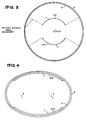
- FIGURE 3 Another exemplary embodiment is shown in FIGURE 3.
- the y-gradient coil arcs are now of lesser extent so as to define a still generally rectangular patient access area 100 which might also be called a (horizontal) "key-hole" shape in cross section (with a suitable physical space boundary interposed between the y and x coil segments as depicted by dotted lines).
- FIGURE 4 Such an embodiment is depicted in FIGURE 4 where the x,y,z coil segments are all essentially co-located at an elliptical boundary of the patient access area 100 having foci f1 and f2.
- the x-gradient coil conductors may be disposed in the usual saddle coil configuration within the elliptical x-coil arc orthogonally to the conductors in the elliptical y-coil arc (which latter conductors provide the y-gradient coils).
- a combination of circular, elliptical or other shaped arcs could also be used for the cross sectional shape of one or more of the gradient coils as should now be apparent.
Landscapes
- Physics & Mathematics (AREA)
- Condensed Matter Physics & Semiconductors (AREA)
- General Physics & Mathematics (AREA)
- Magnetic Resonance Imaging Apparatus (AREA)
Claims (12)
- Anordnung von Magnetfeldgradientenspulen, um steuerbare dreidimensionale Gradienten entlang der x,y,z-Achsen in einem Magnetresonanzbildgebersystem zu erzeugen, das ein Magnetfeld entlang der z-Achse hat, gekennzeichnet durch wenigstens einige Spulenleiter (y), die im wesentlichen näher zur z-Achse angeordnet sind als die anderen (x,z) und innerhalb, entlang der z-Achse, einen Patientenzugangsraum festlegen, der einen Querschnitt senkrecht zur z-Achse hat, dessen horizontale Ausdehnung im wesentlichen größer ist als seine vertikale Ausdehnung.
- Magnetresonanzbildgebersystem mit einer Anordnung von Magnetfeldgradientenspulen nach Anspruch 1, das innerhalb einer ein statisches Magnetfeld erzeugenden Struktur angeordnet ist und mit der MRI-Treiber- und -Steuervorrichtung elektrisch verbunden ist, um während eines MRI-Bildgebungsablaufs eine vorgegebene Folge von Stromimpulsen durch besagte Gradientenspulen zu schicken.
- Anordnung von Magnetfeldgradientenspulen nach Anspruch 1, in der:
x und z Gradientenspulensegmente näherungsweise mit gleichem Abstand von der z-Achse angebracht sind, und wenigstens einige y-Gradientenspulenelemente im wesentlichen näher an der z-Achse angebracht sind als die x- und z-Gradientenspulensegmente. - Anordnung von Magnetfeldgradientenspulen nach Anspruch 1, in der
wenigstens ein erster Satz von Spulensegmenten mit einem ersten minimalen Abstand von der z-Achse angeordnet ist und wenigstens ein zweiter Satz von Spulensegmenten mit einem zweiten minimalen Abstand von der z-Achse angeordnet ist,
der zweite Abstand wesentlich geringer ist als der erste Abstand,
der erste und zweite Satz der Spulensegmente so angeordnet ist, daß eine im allgemeinen rechteckige Patientenzugangsöffnung entlang der z-Achse festgelegt wird. - Anordnung nach Anspruch 4, in der die Patientenöffnung schlüssellochförmig ist und von Paaren gegenüberliegender Bögen mit unterschiedlichen Ausdehnungen gebildet wird.
- Anordnung nach Anspruch 5, in der mindestens einer dieser Bögen eine elliptische Form hat.
- Anordnung nach Anspruch 4, in der eines der Spulensegmente orthogonal in bezug auf ein anderes der Spulensegmente angeordnet ist, um eine Patientenzugangsöffnung festzulegen, die sich entlang der z-Achse erstreckt, die im allgemeinen eine rechteckige Querschnittsform und eine den unterschiedlichen ersten und zweiten minimalen Abständen entsprechende Größe hat.
- Anordnung nach Anspruch 4, in der die Patientenzugangsöffnung einen Querschnitt hat, der sich horizontal zwischen kreisförmigen Bögen, die auf besagter z-Achse zentriert sind, und vertikal zwischen kreisförmigen Bögen, die auf den jeweiligen Achsen zentriert sind, die bezüglich der z-Achse nach oben und unten versetzt sind, erstreckt.
- Anordnung nach Anspruch 1, ferner gekennzeichnet durch:
eine z-Achsen-Gradientenspule mit Spulensegmenten, die so angeordnet sind, daß sie einen Gradienten entlang der z-Achse in einem statischen magnetischen Feld erzeugen, das entlang der z-Achse ausgerichtet ist;
eine x-Achsen-Gradientenspule mit Spulensegmenten, die so angeordnet sind, daß sie einen Gradienten entlang der x-Achse in dem statischen magnetischen Feld erzeugen;
eine y-Achsen-Gradientenspule mit Spulensegmenten, die so angeordnet sind, daß sie einen Gradienten entlang der z-Achse in dem statischen magnetischen Feld erzeugen;
wenigstens einige der besagten y-Achsen-Spulensegmente, die im wesentlichen näher zur z-Achse als die x-Achsen-Spulensegmente angeordnet sind. - Anordnung nach Anspruch 9, in der die Spulensegmente gekrümmt sind und wo die y-Achsen-Spulensegmente auf Achsen zentriert sind, die von der z-Achse versetzt sind, während die x- und z-Achsenspulensegmente auf der z-Achse zentriert sind.
- Anordnung von mehreren Magnetfeldgradientenspulen nach Anspruch 1, in der:
wenigstens eine der Spulen einen nicht kreisförmigen Querschnitt hat, um wenigstens teilweise eine nicht kreisförmige Patientenzugangsöffnung innerhalb festzulegen, die sich entlang der z-Achse erstreckt. - Vorrichtung von magnetischen Gradientenspulen nach Anspruch 1, in der:
x- und z-Gradientenspulenelemente auf der z-Achse zentriert sind und
wenigstens einige y-Gradienten-Spulenelemente auf einer Achse zentriert sind, die nichzt parallel zur z-Achse ist.
Priority Applications (1)
| Application Number | Priority Date | Filing Date | Title |
|---|---|---|---|
| AT88308716T ATE99803T1 (de) | 1987-10-07 | 1988-09-20 | Satz magnetischer gradientenspulen fuer ein kernmagnetisches resonanzsystem mit im wesentlichen unterschiedlichen spulenabstaenden zum patienten. |
Applications Claiming Priority (2)
| Application Number | Priority Date | Filing Date | Title |
|---|---|---|---|
| US07/105,738 US4820988A (en) | 1987-10-07 | 1987-10-07 | Magnetic gradient coil set for nuclear magnetic resonace system having substantially different coil-patient spacings |
| US105738 | 1987-10-07 |
Publications (3)
| Publication Number | Publication Date |
|---|---|
| EP0313213A2 EP0313213A2 (de) | 1989-04-26 |
| EP0313213A3 EP0313213A3 (en) | 1990-10-17 |
| EP0313213B1 true EP0313213B1 (de) | 1994-01-05 |
Family
ID=22307517
Family Applications (1)
| Application Number | Title | Priority Date | Filing Date |
|---|---|---|---|
| EP88308716A Expired - Lifetime EP0313213B1 (de) | 1987-10-07 | 1988-09-20 | Satz magnetischer Gradientenspulen für ein kernmagnetisches Resonanzsystem mit im wesentlichen unterschiedlichen Spulenabständen zum Patienten |
Country Status (5)
| Country | Link |
|---|---|
| US (1) | US4820988A (de) |
| EP (1) | EP0313213B1 (de) |
| JP (1) | JP2584005B2 (de) |
| AT (1) | ATE99803T1 (de) |
| DE (1) | DE3886886T2 (de) |
Families Citing this family (26)
| Publication number | Priority date | Publication date | Assignee | Title |
|---|---|---|---|---|
| JP2558727B2 (ja) * | 1987-08-25 | 1996-11-27 | 株式会社東芝 | 磁気共鳴診断装置 |
| JP2816157B2 (ja) * | 1988-09-19 | 1998-10-27 | 株式会社日立製作所 | 核磁気共鳴を用いた検査装置 |
| US5177441A (en) * | 1989-06-16 | 1993-01-05 | Picker International, Inc. | Elliptical cross section gradient oil |
| DE69020113T2 (de) * | 1989-11-24 | 1996-02-29 | Toshiba Kawasaki Kk | Empfangsspule für einen Apparat zur Bilderzeugung mit magnetischer Kernresonanz. |
| US5146197A (en) * | 1990-01-25 | 1992-09-08 | University Of Pittsburgh | Self-shielding homogeneous spherical gradient coils |
| AU4374993A (en) * | 1992-07-10 | 1994-01-31 | Doty Scientific, Inc. | Solenoidal, octopolar, transverse gradient coils |
| US5365173A (en) * | 1992-07-24 | 1994-11-15 | Picker International, Inc. | Technique for driving quadrature dual frequency RF resonators for magnetic resonance spectroscopy/imaging by four-inductive loop over coupling |
| JP3341306B2 (ja) * | 1992-08-06 | 2002-11-05 | 株式会社日立製作所 | 傾斜磁場コイル及びこれを用いる核磁気共鳴撮影装置 |
| US5554929A (en) * | 1993-03-12 | 1996-09-10 | Doty Scientific, Inc. | Crescent gradient coils |
| US5530355A (en) * | 1993-05-13 | 1996-06-25 | Doty Scientific, Inc. | Solenoidal, octopolar, transverse gradient coils |
| US5412322A (en) * | 1993-06-24 | 1995-05-02 | Wollin Ventures, Inc. | Apparatus and method for spatially ordered phase encoding and for determining complex permittivity in magnetic resonance by using superimposed time-varying electric fields |
| DE19504171C2 (de) * | 1995-02-07 | 1998-04-30 | Siemens Ag | Trennbare, lokale Gradientenspulenanordnung für Kernspintomographiegeräte |
| IT1288452B1 (it) | 1996-11-20 | 1998-09-22 | Esaote Spa | Metodo per migliorare l'efficienza di sistemi di bobine in particolare nei dispositivi di acquisizione di immagini mediante |
| DE19653449C2 (de) * | 1996-12-20 | 1999-11-11 | Siemens Ag | Gradientenspulenanordnung für ein Kernspintomographiegerät |
| DE19943372C2 (de) * | 1999-09-10 | 2001-07-19 | Siemens Ag | Gradientenspulensystem für ein Magnetresonanztomographiegerät |
| DE19953748A1 (de) * | 1999-11-09 | 2001-05-10 | Philips Corp Intellectual Pty | MR-Gerät |
| DE10202986A1 (de) * | 2002-01-26 | 2003-07-31 | Philips Intellectual Property | Spulensystem für eine MR-Apparatur sowie MR-Apparatur mit einem solchen Spulensystem |
| JP4789254B2 (ja) * | 2006-05-01 | 2011-10-12 | 株式会社日立メディコ | 水平静磁場方式の楕円筒状ガントリおよびそれに適合するアクティブシールド型傾斜磁場コイル装置を有する磁気共鳴イメージング装置 |
| DE102006034472A1 (de) * | 2006-07-26 | 2008-01-31 | Forschungszentrum Jülich GmbH | Vorrichtung zur Beaufschlagung einer Probe mit einem Magnetfeld |
| KR100805953B1 (ko) * | 2006-07-27 | 2008-02-21 | 경상대학교산학협력단 | 갈변화 방지 및 풍미가 개선된 우렁쉥이 젓갈의 제조방법 |
| EP2089734A1 (de) * | 2006-11-03 | 2009-08-19 | Koninklijke Philips Electronics N.V. | Geteilte gradientenspule für die magnetresonanzabbildung |
| JP2010046495A (ja) * | 2009-09-04 | 2010-03-04 | Toshiba Corp | Mri用傾斜磁場コイルの設計方法 |
| US9075119B2 (en) * | 2009-09-30 | 2015-07-07 | Hitachi Medical Corporation | Gradient magnetic field coil and magnetic resonance imaging device |
| CN103327890B (zh) * | 2011-01-14 | 2016-07-06 | 株式会社日立医疗器械 | 倾斜磁场线圈装置以及磁共振成像装置 |
| CN105718729B (zh) * | 2016-01-20 | 2018-07-24 | 河海大学 | 一种柱面轴向梯度线圈设计中磁场与电感值的计算方法 |
| EP3594707B1 (de) * | 2018-07-09 | 2023-06-07 | Esaote S.p.A. | Verfahren zum entwerfen von gradientenspulen für mrt-systeme und mrt-system mit solchen gradientenspulen |
Family Cites Families (9)
| Publication number | Priority date | Publication date | Assignee | Title |
|---|---|---|---|---|
| US3622869A (en) * | 1967-06-28 | 1971-11-23 | Marcel J E Golay | Homogenizing coils for nmr apparatus |
| US3569823A (en) * | 1968-10-18 | 1971-03-09 | Perkin Elmer Corp | Nuclear magnetic resonance apparatus |
| US4471305A (en) * | 1978-07-20 | 1984-09-11 | The Regents Of The University Of Calif. | Method and apparatus for rapid NMR imaging of nuclear parameters with an object |
| US4599565A (en) * | 1981-12-15 | 1986-07-08 | The Regents Of The University Of Calif. | Method and apparatus for rapid NMR imaging using multi-dimensional reconstruction techniques |
| US4456881A (en) * | 1982-01-18 | 1984-06-26 | Technicare Corporation | Gradient-coil apparatus for a magnetic resonance system |
| US4564813A (en) * | 1982-11-10 | 1986-01-14 | Picker International, Ltd. | Nuclear magnetic resonance method and apparatus |
| US4642569A (en) * | 1983-12-16 | 1987-02-10 | General Electric Company | Shield for decoupling RF and gradient coils in an NMR apparatus |
| DE3347597A1 (de) * | 1983-12-30 | 1985-07-18 | Philips Patentverwaltung Gmbh, 2000 Hamburg | Hochfrequenz-spulenanordnung zum erzeugen und/oder empfangen von wechselmagnetfeldern |
| FR2571496B1 (fr) * | 1984-10-05 | 1986-12-19 | Commissariat Energie Atomique | Systeme de bobines de production de champs additionnels pour l'obtention, dans un aimant comportant des pieces polaires de polarisation pour imagerie par resonance magnetique nucleaire, de champs de polarisation a gradients constants |
-
1987
- 1987-10-07 US US07/105,738 patent/US4820988A/en not_active Expired - Lifetime
-
1988
- 1988-09-20 AT AT88308716T patent/ATE99803T1/de not_active IP Right Cessation
- 1988-09-20 EP EP88308716A patent/EP0313213B1/de not_active Expired - Lifetime
- 1988-09-20 DE DE3886886T patent/DE3886886T2/de not_active Expired - Fee Related
- 1988-10-07 JP JP63253651A patent/JP2584005B2/ja not_active Expired - Lifetime
Also Published As
| Publication number | Publication date |
|---|---|
| DE3886886T2 (de) | 1994-07-07 |
| DE3886886D1 (de) | 1994-02-17 |
| JPH021238A (ja) | 1990-01-05 |
| ATE99803T1 (de) | 1994-01-15 |
| US4820988A (en) | 1989-04-11 |
| JP2584005B2 (ja) | 1997-02-19 |
| EP0313213A2 (de) | 1989-04-26 |
| EP0313213A3 (en) | 1990-10-17 |
Similar Documents
| Publication | Publication Date | Title |
|---|---|---|
| EP0313213B1 (de) | Satz magnetischer Gradientenspulen für ein kernmagnetisches Resonanzsystem mit im wesentlichen unterschiedlichen Spulenabständen zum Patienten | |
| US6600401B2 (en) | Magnetic apparatus for MRI | |
| US4829252A (en) | MRI system with open access to patient image volume | |
| EP0701700B1 (de) | Akustische abschirmung | |
| US4737716A (en) | Self-shielded gradient coils for nuclear magnetic resonance imaging | |
| US4794338A (en) | Balanced self-shielded gradient coils | |
| US4486711A (en) | Gradient field coil system for nuclear spin tomography | |
| JPS61168904A (ja) | 磁石装置及びその使用方法 | |
| US6011393A (en) | Self-supporting RF coil for MRI | |
| EP0676647A1 (de) | Offener Magnet für Bilderzeugung durch magnetische Resonanz | |
| EP1725886B1 (de) | Asymmetrische ultrakurze gradientenspule für ein magnetresonanz-abbildungssystem | |
| EP0307981A1 (de) | Magnetisches Resonanzgerät mit integrierten HF-Gradientenspulen | |
| US4728895A (en) | System of coils for producing additional fields for obtaining polarization fields with constant gradients in a magnet having polarization pole pieces for image production by nuclear magnetic resonance | |
| US6950001B2 (en) | Superconducting open MRI magnet with transverse magnetic field | |
| US5293126A (en) | Local transverse gradient coil | |
| JPH10179552A (ja) | 核スピントモグラフィ装置用の勾配コイル装置 | |
| US4755755A (en) | Compact transverse magnetic gradient coils and dimensioning method therefor | |
| US5088185A (en) | Method for manufacturing gradient coil system for a nuclear magnetic resonance tomography apparatus | |
| US20050122106A1 (en) | Gradient coil arrangement | |
| CA2939982C (en) | Magnetic resonance imaging with a single thick loop | |
| US6674284B2 (en) | Magnetic resonance apparatus having a horizontal basic magnetic field | |
| JP2022167998A5 (de) | ||
| JPH03210236A (ja) | 磁気共鳴イメージング装置 | |
| JPH01136646A (ja) | 高周波コイル |
Legal Events
| Date | Code | Title | Description |
|---|---|---|---|
| PUAI | Public reference made under article 153(3) epc to a published international application that has entered the european phase |
Free format text: ORIGINAL CODE: 0009012 |
|
| AK | Designated contracting states |
Kind code of ref document: A2 Designated state(s): AT BE CH DE ES FR GB GR IT LI LU NL SE |
|
| PUAL | Search report despatched |
Free format text: ORIGINAL CODE: 0009013 |
|
| AK | Designated contracting states |
Kind code of ref document: A3 Designated state(s): AT BE CH DE ES FR GB GR IT LI LU NL SE |
|
| 17P | Request for examination filed |
Effective date: 19901227 |
|
| 17Q | First examination report despatched |
Effective date: 19930506 |
|
| GRAA | (expected) grant |
Free format text: ORIGINAL CODE: 0009210 |
|
| AK | Designated contracting states |
Kind code of ref document: B1 Designated state(s): AT BE CH DE ES FR GB GR IT LI LU NL SE |
|
| PG25 | Lapsed in a contracting state [announced via postgrant information from national office to epo] |
Ref country code: IT Free format text: LAPSE BECAUSE OF FAILURE TO SUBMIT A TRANSLATION OF THE DESCRIPTION OR TO PAY THE FEE WITHIN THE PRE;WARNING: LAPSES OF ITALIAN PATENTS WITH EFFECTIVE DATE BEFORE 2007 MAY HAVE OCCURRED AT ANY TIME BEFORE 2007. THE CORRECT EFFECTIVE DATE MAY BE DIFFERENT FROM THE ONE RECORDED.SCRIBED TIME-LIMIT Effective date: 19940105 Ref country code: GR Free format text: LAPSE BECAUSE OF FAILURE TO SUBMIT A TRANSLATION OF THE DESCRIPTION OR TO PAY THE FEE WITHIN THE PRESCRIBED TIME-LIMIT Effective date: 19940105 Ref country code: AT Effective date: 19940105 Ref country code: LI Effective date: 19940105 Ref country code: FR Effective date: 19940105 Ref country code: CH Effective date: 19940105 Ref country code: BE Effective date: 19940105 Ref country code: SE Effective date: 19940105 |
|
| REF | Corresponds to: |
Ref document number: 99803 Country of ref document: AT Date of ref document: 19940115 Kind code of ref document: T |
|
| REF | Corresponds to: |
Ref document number: 3886886 Country of ref document: DE Date of ref document: 19940217 |
|
| REG | Reference to a national code |
Ref country code: CH Ref legal event code: PL |
|
| PG25 | Lapsed in a contracting state [announced via postgrant information from national office to epo] |
Ref country code: ES Free format text: LAPSE BECAUSE OF FAILURE TO SUBMIT A TRANSLATION OF THE DESCRIPTION OR TO PAY THE FEE WITHIN THE PRESCRIBED TIME-LIMIT Effective date: 19940416 |
|
| EN | Fr: translation not filed | ||
| PGFP | Annual fee paid to national office [announced via postgrant information from national office to epo] |
Ref country code: LU Payment date: 19940801 Year of fee payment: 7 |
|
| PGFP | Annual fee paid to national office [announced via postgrant information from national office to epo] |
Ref country code: GB Payment date: 19940825 Year of fee payment: 7 |
|
| PGFP | Annual fee paid to national office [announced via postgrant information from national office to epo] |
Ref country code: ES Payment date: 19940914 Year of fee payment: 7 |
|
| PLBE | No opposition filed within time limit |
Free format text: ORIGINAL CODE: 0009261 |
|
| STAA | Information on the status of an ep patent application or granted ep patent |
Free format text: STATUS: NO OPPOSITION FILED WITHIN TIME LIMIT |
|
| 26N | No opposition filed | ||
| PGFP | Annual fee paid to national office [announced via postgrant information from national office to epo] |
Ref country code: NL Payment date: 19950811 Year of fee payment: 8 |
|
| PGFP | Annual fee paid to national office [announced via postgrant information from national office to epo] |
Ref country code: DE Payment date: 19950818 Year of fee payment: 8 |
|
| PG25 | Lapsed in a contracting state [announced via postgrant information from national office to epo] |
Ref country code: GB Effective date: 19950920 Ref country code: LU Free format text: LAPSE BECAUSE OF NON-PAYMENT OF DUE FEES Effective date: 19950920 |
|
| GBPC | Gb: european patent ceased through non-payment of renewal fee |
Effective date: 19950920 |
|
| PG25 | Lapsed in a contracting state [announced via postgrant information from national office to epo] |
Ref country code: NL Effective date: 19970401 |
|
| NLV4 | Nl: lapsed or anulled due to non-payment of the annual fee |
Effective date: 19970401 |
|
| PG25 | Lapsed in a contracting state [announced via postgrant information from national office to epo] |
Ref country code: DE Effective date: 19970603 |