EP0317990A1 - Method for self-cleaning of a strainer system included in an apparatus for washing articles, preferably a dishwasher and apparatus for carrying out said method - Google Patents
Method for self-cleaning of a strainer system included in an apparatus for washing articles, preferably a dishwasher and apparatus for carrying out said method Download PDFInfo
- Publication number
- EP0317990A1 EP0317990A1 EP88119536A EP88119536A EP0317990A1 EP 0317990 A1 EP0317990 A1 EP 0317990A1 EP 88119536 A EP88119536 A EP 88119536A EP 88119536 A EP88119536 A EP 88119536A EP 0317990 A1 EP0317990 A1 EP 0317990A1
- Authority
- EP
- European Patent Office
- Prior art keywords
- strainer
- wash
- washing
- liquid
- drainage
- Prior art date
- Legal status (The legal status is an assumption and is not a legal conclusion. Google has not performed a legal analysis and makes no representation as to the accuracy of the status listed.)
- Granted
Links
- 238000000034 method Methods 0.000 title claims description 34
- 238000004140 cleaning Methods 0.000 title claims description 22
- 238000005406 washing Methods 0.000 title claims description 5
- 238000011010 flushing procedure Methods 0.000 claims abstract description 37
- 239000007788 liquid Substances 0.000 claims abstract description 32
- 239000007921 spray Substances 0.000 claims abstract description 31
- 230000004087 circulation Effects 0.000 claims abstract description 20
- 239000002245 particle Substances 0.000 claims description 9
- XLYOFNOQVPJJNP-UHFFFAOYSA-N water Substances O XLYOFNOQVPJJNP-UHFFFAOYSA-N 0.000 abstract description 63
- 238000005086 pumping Methods 0.000 description 6
- 230000000694 effects Effects 0.000 description 4
- 238000010438 heat treatment Methods 0.000 description 4
- 206010016825 Flushing Diseases 0.000 description 3
- 239000002184 metal Substances 0.000 description 3
- 229910052729 chemical element Inorganic materials 0.000 description 2
- 230000006866 deterioration Effects 0.000 description 2
- 238000011161 development Methods 0.000 description 2
- 230000018109 developmental process Effects 0.000 description 2
- 238000010586 diagram Methods 0.000 description 2
- 239000002699 waste material Substances 0.000 description 2
- 230000002730 additional effect Effects 0.000 description 1
- 239000007864 aqueous solution Substances 0.000 description 1
- OMFRMAHOUUJSGP-IRHGGOMRSA-N bifenthrin Chemical compound C1=CC=C(C=2C=CC=CC=2)C(C)=C1COC(=O)[C@@H]1[C@H](\C=C(/Cl)C(F)(F)F)C1(C)C OMFRMAHOUUJSGP-IRHGGOMRSA-N 0.000 description 1
- 230000000295 complement effect Effects 0.000 description 1
- 239000003599 detergent Substances 0.000 description 1
- 230000002542 deteriorative effect Effects 0.000 description 1
- 238000001035 drying Methods 0.000 description 1
- 239000011521 glass Substances 0.000 description 1
- 229920000136 polysorbate Polymers 0.000 description 1
- 230000002035 prolonged effect Effects 0.000 description 1
- 239000002689 soil Substances 0.000 description 1
Images

Classifications
-
- A—HUMAN NECESSITIES
- A47—FURNITURE; DOMESTIC ARTICLES OR APPLIANCES; COFFEE MILLS; SPICE MILLS; SUCTION CLEANERS IN GENERAL
- A47L—DOMESTIC WASHING OR CLEANING; SUCTION CLEANERS IN GENERAL
- A47L15/00—Washing or rinsing machines for crockery or tableware
- A47L15/42—Details
- A47L15/4202—Water filter means or strainers
- A47L15/4208—Arrangements to prevent clogging of the filters, e.g. self-cleaning
Definitions
- the invention relates to a method for self-cleaning of a strainer system included in an apparatus for washing articles, preferably a dish-washer, according to the introductory part of claim 1.
- the invention also relates to an apparatus according to the introductory part of claim 6 adapted for carrying out the afore-mentioned method.
- the flushing system is provided with a strainer, the upper surface of which is slightly inclined towards the centre of the strainer.
- the dirt flushed to the bottom by the water adheres to the surface of the strainer due to the powerful suction force of the circulation pump. This soiling is particularly pronounced on the upper surface of the strainer.
- a pre-wash-up is terminated by ceasing of the flushing (by stopping the circulation pump), whereafter the dish- water is pumped out with the aid of a discharge pump.
- Part of the dirt deposited on the surface of the fine strainer is discharged with the dish-water whereas part of the dirt remains on the strainer surface.
- this remaining dirt will soil the dish-water and cause resoiling of the articles being washed up.
- This resoiling requires a relatively large number of rinsings after the main wash-up, for example three such rinsings.
- the consumption of water for a complete wash-up procedure is therefore relatively great. This is a considerable disadvantage since both the water costs and the cost of heating the water are relatively high.
- a dish-washer of the kind described above is previously known, in which, during the pumping out of washing-up liquid after a wash-up step, the circulation pump is kept running while the liquid is continuously pumped out at least until the liquid level has dropped to below the upper strainer surface of the fine strainer. This is done for the purpose of obtaining a rinsing of the fine strainer.
- tests performed have shown that, in a typical dish-washer, no significant improvement is achieved in this way. No real cleaning of the strainer surface is obtained until, during the pumping out, the liquid surface has dropped to such an extent that the strainer surface is exposed. The remaining quantity of liquid is then so small that the further pumping out is performed very rapidly, and no significant cleaning of the filter surface is ever performed.
- dish-washer of the kind referred to in this specification in which the spray arm has nozzles on its underside which provide a flow of water in the washing-up liquid with a component parallel to the surface of the fine strainer.
- the liquid level during the wash-up steps is so high that the liquid surface lies above the strainer surface.
- the proposed method therefore only provides a certain amount of flow in the washing-up liquid along the strainer surface and only incomplete cleaning of the strainer.
- the circulation pump working during the wash-up steps has a high capacity and generates a powerful suction force. This causes particles of dirt to adhere to the surface of the strainer, which further prevents an efficient cleaning of the strainer.
- the invention aims to provide a method for cleaning the strainer system of a washing-apparatus of the above-mentioned kind, by means of which, during an early stage of the wash-up procedure, a very large part of the dirt removed from the articles to be washed is discharged from the washing-apparatus, whereby the resoiling of the articles during subsequent wash-up steps is greatly reduced and hence also the number of required rinsings and, in turn, the total water consumption during the whole wash-up procedure.
- the invention also aims to provide a device for carrying out this method and, in the same way and hence without deterioration of the wash-up result, for considerably reducing the volume of water required for the wash-up procedure.
- a washing-apparatus for carrying out the afore-mentioned method is, according to the invention. characterized by the features of the characterizing portion of claim 6.
- FIG. 1 shows a dish-washer of the kind to which the present invention relates. It comprises a container 1 with withdrawable baskets 2 and 3 for the articles to be washed up.
- a typical use of a machine of this kind is as household dish-washer, whereby the articles to be washed up normally consist of plates, glasses, cutlery, pots, etc.
- Below the upper basket 2 an upper spray arm 4 is arranged, which is supplied with flushing water through the pipe 11 during the washing operation.
- the dish-water is sprayed out through a number of spray nozzles 41 on the arm, at least some of these spray nozzles being inclined horizontally in order to impart rotation to the spray arm during the flushing.
- the spray arm is journalled to be easily movable on a stub tube 12 serving as a hub, through which stub tube the flushing water from the pipe 11 flows out into the spray arm through openings 14.
- the spray arm 5 mounted below the lower basket 3 is mounted to be easily movable on a stub tube 10 serving as a hub, the arm being supplied with dish-water during the flushing through openings 13, and the dish-water flowing out through a number of spray nozzles 51 on the arm.
- the dish-water sprayed out through the nozzles of the spray arms during the flushing runs down into the lower part of the container and is collected in a sump 6.
- the flushing system includes a circulation pump 8.
- the flushing system is provided with a strainer 15.
- the strainer 15 has an upper strainer surface slightly inclined towards the centre of the strainer as well as a stub tube 152 arranged centrally in the strainer and extending down to the bottom of the sump 6.
- Both the upper strainer surface 151 and the stub tube 152 are constructed as strainers, for example made of sheet metal and provided with a large number of fine holes.
- a waste pipe 16 is arranged through which the dish-water can be drained off with the aid of a discharge pump 17 and an outlet pipe 18.
- a coarse strainer 19 is arranged at the outlet from the dish-washer.
- Dish-water is supplied to the machine through a supply pipe 20, a controlled movement downwards into the container 1 being imparted to the dish-water by a shield 23.
- a solenoid valve 21 is arranged in the supply pipe.
- the function of the dish-washer is controlled and monitored by a control means 24. In conventional manner, this may consist either of a conventional, rotary electromechanical control means, or of a microprocessor or the like which is provided with suitable input and output means.
- a number of schematically shown operating members 25,26,27 are arranged.
- a typical water level during any of the wash-up steps is shown by the horizontal line A in Figure 1.
- the control means 24 controls the wash-up procedure in a plurality of consecutive wash-up steps, for example pre-wash-up, main wash-up and three rinsings.
- a flushing step may possibly be provided before the pre-wash-up step.
- an intermediate rinsing step may be provided, and after the last rinsing a drying step may be provided during which the washed-up articles are dried with the aid of heating elements activated by the control means and built into the dish-washer.
- the heating elements may be used for heating the admitted dish-water to the desired temperature at the beginning of each wash-up step.
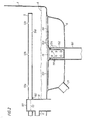
- Figure 2 shows in more detail the strainer system of the dish-washer as well as the lower spray arm 5.
- the flushing water is supplied to the spray arm through the stub tube 10 and the openings 13 provided therein.
- the spray arm rests on a flange 102 on the stub tube 10 and is readily movable around the stub tube.
- the spray arm has, for example, the three spray nozzles 51a,51b and 51c, arranged on the upper side, as well as an additional nozzle 51d on the underside.
- the Figure shows the fine strainer 15 with its upper strainer surface 151, and the stub tube 152. These two elements may be made of sheet metal and are provided with a large number of relatively fine holes 153,154.
- a stub tube 71 is provided for connection of the pipe or hose 7 to the circulation pump 8.
- the sump has a stub tube 161 for connection of the pipe or hose 16 leading to the discharge pump 17.
- the coarse strainer 19, which is to capture such larger objects that may cause clogging of the pump, is designed as a coarse-meshed metal or plastic strainer with holes 191 and is suspended from a flange in the stub tube 152 of the fine strainer.
- the circulation pump 8 is activated and circulates dish-water through the flushing system.
- the dish-water has the level designated A in Figure 1 and Figure 2.
- the pre-wash-up is terminated by the circulation pump 8 being stopped.
- Dish-water is pumped away under simultaneous flushing. During this pumping away, part of the dirt present in the dish-washer tends to float towards the drainage point and is transported away.
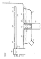
- This water level is designated B in Figure 3.
- This water level may, for example, correspond to a residual water quantity of 40% of the original water quantity.
- the strainer surface 151 will become exposed, and after that the water stream flowing towards the drainage point provides rinsing away of dirt from the strainer surface 15.
- the particles of dirt which are rinsed away accompany the water stream down into the stub tube 152 and are transported away by the discharge pump.
- the discharge pump 17 is stopped while the flushing is continued during a period of, for example, 40 seconds.
- the upper surface of the fine strainer is all the time exposed to the powerful water stream flowing towards the drainage point, and there is ample time for the water stream to effectively rinse away practically all of the dirt particles present on the strainer surface. These particles are rinsed down into the stub tube 152 where they are collected.
- the discharge pump 17 is stopped and the next wash-up step can be started.
- the cleaning method according to the invention provides the greatest effect if it is performed after the pre-wash-up step or a corresponding wash-up step, since it is at this stage that a considerable quantity of loose dirt is rinsed away from the articles being washed up. It is self-evident, however, that the cleaning method can be carried out, as an alternative or as a complement, after the main wash-up step.
- Figures 2 and 3 show how the lower spray arm 5 is provided on its underside with a spray nozzle 51d, through which water is flushed downwards.
- the flushing from this spray nozzle provides an additional improvement of the cleaning of the upper surface of the fine strainer.
- the underside of the spray arm 5 can, of course, be provided with more spray nozzles than the only one shown.
- the drainage of the dish-water has taken place with the aid of a discharge pump.
- the dish-water may, of course, be drained off by being discharged, via a solenoid valve or the like, downwards to a floor drain or the like.
- wash-water has been used for the liquid used during the washing-up, which liquid normally consists of water or an aqueous solution of a detergent.
- other washing-up liquids can, of course, be used, for example in those cases where a dish-washer is utilized for cleaning in industry.
Landscapes
- Washing And Drying Of Tableware (AREA)
- Cleaning By Liquid Or Steam (AREA)
Abstract
Description
- The invention relates to a method for self-cleaning of a strainer system included in an apparatus for washing articles, preferably a dish-washer, according to the introductory part of claim 1. The invention also relates to an apparatus according to the introductory part of
claim 6 adapted for carrying out the afore-mentioned method. - During, for example, the pre-wash-up step in a dish-washer, normally large quantities of dirt are removed from the articles to be washed up. The dirt accompanies the water flowing down to the bottom of the container of the dish-washer. To prevent resoiling of the articles, the flushing system is provided with a strainer, the upper surface of which is slightly inclined towards the centre of the strainer. The dirt flushed to the bottom by the water adheres to the surface of the strainer due to the powerful suction force of the circulation pump. This soiling is particularly pronounced on the upper surface of the strainer. In known dish-washers a pre-wash-up is terminated by ceasing of the flushing (by stopping the circulation pump), whereafter the dish- water is pumped out with the aid of a discharge pump. Part of the dirt deposited on the surface of the fine strainer is discharged with the dish-water whereas part of the dirt remains on the strainer surface. During a subsequent wash-up step, for example the main wash-up succeeding the pre-wash-up, this remaining dirt will soil the dish-water and cause resoiling of the articles being washed up. This resoiling requires a relatively large number of rinsings after the main wash-up, for example three such rinsings. The consumption of water for a complete wash-up procedure is therefore relatively great. This is a considerable disadvantage since both the water costs and the cost of heating the water are relatively high.
- Proposals have been made to introduce extra rinsings after the pre-wash-up to rinse away, as far as possible, the dirt removed during the pre-wash-up, thus reducing the resoiling during the main wash-up. However, no reduction of the total number of necessary rinsings and hence of the total water consumption can be obtained in this way. Further, an obvious method of reducing the water consumption would be to reduce the volume of water used during each rinsing. However, it has proved to be difficult to reduce the water consumption in this way, since a volume of water reduced below a certain limit results in the circulation pump sucking air, which leads to a deteriorated flushing action and an increased noise level. Similarly, it has proved to be impossible to reduce the water consumption by reducing the number of rinsings without simultaneously deteriorating the desired good result of the washing-up.
- From DE-A-12 65 7764 a dish-washer of the kind described above is previously known, in which, during the pumping out of washing-up liquid after a wash-up step, the circulation pump is kept running while the liquid is continuously pumped out at least until the liquid level has dropped to below the upper strainer surface of the fine strainer. This is done for the purpose of obtaining a rinsing of the fine strainer. However, tests performed have shown that, in a typical dish-washer, no significant improvement is achieved in this way. No real cleaning of the strainer surface is obtained until, during the pumping out, the liquid surface has dropped to such an extent that the strainer surface is exposed. The remaining quantity of liquid is then so small that the further pumping out is performed very rapidly, and no significant cleaning of the filter surface is ever performed.
- From EP-A-1 222 306 a dish-washer of the kind referred to in this specification is known, in which the spray arm has nozzles on its underside which provide a flow of water in the washing-up liquid with a component parallel to the surface of the fine strainer. In dish-washers of this kind, the liquid level during the wash-up steps is so high that the liquid surface lies above the strainer surface. The proposed method therefore only provides a certain amount of flow in the washing-up liquid along the strainer surface and only incomplete cleaning of the strainer. The circulation pump working during the wash-up steps has a high capacity and generates a powerful suction force. This causes particles of dirt to adhere to the surface of the strainer, which further prevents an efficient cleaning of the strainer.
- The invention aims to provide a method for cleaning the strainer system of a washing-apparatus of the above-mentioned kind, by means of which, during an early stage of the wash-up procedure, a very large part of the dirt removed from the articles to be washed is discharged from the washing-apparatus, whereby the resoiling of the articles during subsequent wash-up steps is greatly reduced and hence also the number of required rinsings and, in turn, the total water consumption during the whole wash-up procedure. The invention also aims to provide a device for carrying out this method and, in the same way and hence without deterioration of the wash-up result, for considerably reducing the volume of water required for the wash-up procedure.
- To achieve this aim the invention suggests a method according to the introductory part of claim 1, which is characterized by the features of the characterizing part of claim 1.
- Further developments of the method according to the invention are characterized by the features of the
claims 2 to 5. - A washing-apparatus for carrying out the afore-mentioned method is, according to the invention. characterized by the features of the characterizing portion of
claim 6. - Further developments of this apparatus are characterized by the features of the additional claims 7 to 11.
- The invention will now be described in greater detail with reference to the accompanying drawings showing - by way of example - in
- Figure 1 a dish-washer of the kind to which the invention relates,
- Figure 2 in more detail the strainer system of the dish-washer of Figure 1,
- Figure 3 the strainer system of the dish-washer and the level of the water surface when flushing with a reduced water quantity according to the invention,
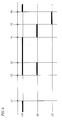
- Figure 4 in the form of a function diagram, the function of a dish-washer for carrying out the method according to the invention.
- Figure 1 shows a dish-washer of the kind to which the present invention relates. It comprises a container 1 with
withdrawable baskets upper basket 2 anupper spray arm 4 is arranged, which is supplied with flushing water through thepipe 11 during the washing operation. The dish-water is sprayed out through a number ofspray nozzles 41 on the arm, at least some of these spray nozzles being inclined horizontally in order to impart rotation to the spray arm during the flushing. The spray arm is journalled to be easily movable on astub tube 12 serving as a hub, through which stub tube the flushing water from thepipe 11 flows out into the spray arm throughopenings 14. In similar manner, thespray arm 5 mounted below thelower basket 3 is mounted to be easily movable on astub tube 10 serving as a hub, the arm being supplied with dish-water during the flushing throughopenings 13, and the dish-water flowing out through a number ofspray nozzles 51 on the arm. The dish-water sprayed out through the nozzles of the spray arms during the flushing runs down into the lower part of the container and is collected in asump 6. The flushing system includes a circulation pump 8. This pump sucks dish-water from thesump 6 through a pipe 7 and recirculates the dish-water via thepipes 9 and 11 to the two spray arms. To prevent resoiling of the items being washed up, the flushing system is provided with astrainer 15. Thestrainer 15 has an upper strainer surface slightly inclined towards the centre of the strainer as well as astub tube 152 arranged centrally in the strainer and extending down to the bottom of thesump 6. Both theupper strainer surface 151 and thestub tube 152 are constructed as strainers, for example made of sheet metal and provided with a large number of fine holes. - In the bottom of the
sump 6 and straight below thestub tube 152 of the fine strainer, awaste pipe 16 is arranged through which the dish-water can be drained off with the aid of adischarge pump 17 and anoutlet pipe 18. To prevent coarser particles from causing clogging of thedischarge pump 17 or thewaste pipe 16, acoarse strainer 19 is arranged at the outlet from the dish-washer. - Dish-water is supplied to the machine through a
supply pipe 20, a controlled movement downwards into the container 1 being imparted to the dish-water by ashield 23. For control of the water supply asolenoid valve 21 is arranged in the supply pipe. The function of the dish-washer is controlled and monitored by a control means 24. In conventional manner, this may consist either of a conventional, rotary electromechanical control means, or of a microprocessor or the like which is provided with suitable input and output means. To start the washing up, select the desired program, etc., a number of schematically shown operatingmembers - A typical water level during any of the wash-up steps is shown by the horizontal line A in Figure 1.
- The control means 24 controls the wash-up procedure in a plurality of consecutive wash-up steps, for example pre-wash-up, main wash-up and three rinsings. Before the pre-wash-up step a flushing step may possibly be provided. Between the pre-wash-up step and the main wash-up step an intermediate rinsing step may be provided, and after the last rinsing a drying step may be provided during which the washed-up articles are dried with the aid of heating elements activated by the control means and built into the dish-washer. In addition, the heating elements may be used for heating the admitted dish-water to the desired temperature at the beginning of each wash-up step.
- Figure 2 shows in more detail the strainer system of the dish-washer as well as the
lower spray arm 5. The flushing water is supplied to the spray arm through thestub tube 10 and theopenings 13 provided therein. The spray arm rests on aflange 102 on thestub tube 10 and is readily movable around the stub tube. The spray arm has, for example, the threespray nozzles additional nozzle 51d on the underside. The Figure shows thefine strainer 15 with itsupper strainer surface 151, and thestub tube 152. These two elements may be made of sheet metal and are provided with a large number of relatively fine holes 153,154. In the left-hand part of the sump 6 astub tube 71 is provided for connection of the pipe or hose 7 to the circulation pump 8. Similarly, in its central part the sump has astub tube 161 for connection of the pipe orhose 16 leading to thedischarge pump 17. Thecoarse strainer 19, which is to capture such larger objects that may cause clogging of the pump, is designed as a coarse-meshed metal or plastic strainer withholes 191 and is suspended from a flange in thestub tube 152 of the fine strainer. - An embodiment of the invention will now be described with reference to Figures 1 to 4. The function diagram in Figure 4 illustrates an example of a method according to the invention. It is shown there how the circulation pump 8 (CP), the discharge pump 17 (DP) and the inlet valve 21 (IV) are activated during different time intervals during the period from the end of the pre-wash-up (t = t1) to the beginning of the main wash-up (t = t5). The time during which one of these members is activated is indicated in Figure 4 by heavy line segments.
- During the pre-wash-up, the circulation pump 8 is activated and circulates dish-water through the flushing system. The dish-water has the level designated A in Figure 1 and Figure 2. At t = t1, the pre-wash-up is terminated by the circulation pump 8 being stopped. According to a preferred embodiment of the invention, the wash-up procedure now takes a pause between t = t1 and t = t2, during which time both the circulation pump 8 and the
discharge pump 17 remain inoperative. This time interval may, for example, amount to 40 seconds. During this pause the major part of the dirt, which as a result of the powerful sucking action of the circulation pump 8, has adhered to the surface of thefine strainer 15, particularly to itsupper surface 151,, will loosen from the filter and float upwards to the water surface. - When the above-mentioned pause is terminated, the control means 24 starts both the circulation pump 8 and the
discharge pump 17 at t = t2. Dish-water is pumped away under simultaneous flushing. During this pumping away, part of the dirt present in the dish-washer tends to float towards the drainage point and is transported away. The pumping out is performed during the interval t = t2 to t = t3, and the duration of this interval is so chosen in relation to the drainage rate that the water level at the end of this interval lies lower than theupper strainer surface 151 of thefine strainer 15. This water level is designated B in Figure 3. This water level may, for example, correspond to a residual water quantity of 40% of the original water quantity. At some time during this pumping-out interval, therefore, thestrainer surface 151 will become exposed, and after that the water stream flowing towards the drainage point provides rinsing away of dirt from thestrainer surface 15. The particles of dirt which are rinsed away accompany the water stream down into thestub tube 152 and are transported away by the discharge pump. - At t = t3, i.e. when the desired water level B in Figure 3 has been reached, the
discharge pump 17 is stopped while the flushing is continued during a period of, for example, 40 seconds. During this prolonged interval the upper surface of the fine strainer is all the time exposed to the powerful water stream flowing towards the drainage point, and there is ample time for the water stream to effectively rinse away practically all of the dirt particles present on the strainer surface. These particles are rinsed down into thestub tube 152 where they are collected. - At t = t4, the circulation pump 8 is stopped and the
discharge pump 17 started. The residual water quantity, together with dirt particles present in thestub tube 152, are then transported away. - The pumping out continues for such a long time that all the dish-water, together with residual dirt particles, has been safely discharged. At t = t5 the
discharge pump 17 is stopped and the next wash-up step can be started. Typically, this constitutes the so-called main wash-up, which is started by theinlet valve 20 being opened, at t = t5, and being held open for such an adaptable time interval that the water quantity in the container reaches the desired level. The filling of water is terminated at t = t6, whereafter the flushing system is started and the main wash-up is carried out. - Compared with prior art wash-up procedures, a considerable reduction of the amount of dirt remaining in the dish-washer after the pre-wash-up step, or the like, is obtained by the invention. This is achieved by the use of dish-water already present in the dish-washer and previously used. No additional supply of dish-water whatsoever is thus required to achieve this effect. The greatly reduced amount of dirt means that the water which is used during a subsequent wash-up step, typically the main wash up, will be much cleaner than what has previously been the case. This in turn means that the so-called resoiling of the articles being washed up is greatly reduced and hence also the need of a subsequent rinsing step. It has proved that with a wash-up method according to the invention, the number of rinsings following the main wash-up step can be reduced from three to two. Further, it has proved that the water quantity used during each wash-up step can be reduced, typically by about 20%. Taken together these effects of the invention permit the total water consumption for a wash-up procedure to be reduced by, for example, 35%. It has further been found that this considerable reduction of the water consumption can be obtained without any deterioration of the wash-up result whatsoever.
- The cleaning method according to the invention provides the greatest effect if it is performed after the pre-wash-up step or a corresponding wash-up step, since it is at this stage that a considerable quantity of loose dirt is rinsed away from the articles being washed up. It is self-evident, however, that the cleaning method can be carried out, as an alternative or as a complement, after the main wash-up step.
- Figures 2 and 3 show how the
lower spray arm 5 is provided on its underside with aspray nozzle 51d, through which water is flushed downwards. The flushing from this spray nozzle provides an additional improvement of the cleaning of the upper surface of the fine strainer. If desired, in order to further enhance the flushing effect on the strainer, the underside of thespray arm 5 can, of course, be provided with more spray nozzles than the only one shown. - In the embodiment described above, the drainage of the dish-water has taken place with the aid of a discharge pump. In those cases where a level difference need not be overcome, the dish-water may, of course, be drained off by being discharged, via a solenoid valve or the like, downwards to a floor drain or the like.
- In the foregoing description the designation "dish-water" has been used for the liquid used during the washing-up, which liquid normally consists of water or an aqueous solution of a detergent. Also other washing-up liquids can, of course, be used, for example in those cases where a dish-washer is utilized for cleaning in industry.
Claims (11)
Applications Claiming Priority (2)
| Application Number | Priority Date | Filing Date | Title |
|---|---|---|---|
| SE8704705 | 1987-11-26 | ||
| SE8704705A SE459554B (en) | 1987-11-26 | 1987-11-26 | PROCEDURE FOR SOIL CLEANING OF SILVER SYSTEM BY DISHWASHER AND DISHWASHER WITH ORGAN BEFORE IMPLEMENTATION OF THE PROCEDURE |
Publications (2)
| Publication Number | Publication Date |
|---|---|
| EP0317990A1 true EP0317990A1 (en) | 1989-05-31 |
| EP0317990B1 EP0317990B1 (en) | 1992-04-22 |
Family
ID=20370405
Family Applications (1)
| Application Number | Title | Priority Date | Filing Date |
|---|---|---|---|
| EP88119536A Expired EP0317990B1 (en) | 1987-11-26 | 1988-11-24 | Method for self-cleaning of a strainer system included in an apparatus for washing articles, preferably a dishwasher and apparatus for carrying out said method |
Country Status (6)
| Country | Link |
|---|---|
| US (1) | US5097855A (en) |
| EP (1) | EP0317990B1 (en) |
| AU (1) | AU612429B2 (en) |
| DE (1) | DE3870414D1 (en) |
| ES (1) | ES2032521T3 (en) |
| SE (1) | SE459554B (en) |
Cited By (9)
| Publication number | Priority date | Publication date | Assignee | Title |
|---|---|---|---|---|
| DE29607001U1 (en) * | 1996-04-17 | 1996-07-11 | ADEK Bauteile GmbH, 40699 Erkrath | Sieve for dishwashers, especially dishwashers |
| AU681005B2 (en) * | 1994-04-26 | 1997-08-14 | Premark Feg L.L.C. | Method of operating a warewasher drain valve |
| EP0998872A1 (en) * | 1998-11-02 | 2000-05-10 | Electrolux Zanussi S.p.A. | Working programme for dishwashing machines |
| EP1262306A1 (en) * | 2001-05-23 | 2002-12-04 | Novartis AG | System and method for treating articles like ophthalmic lenses, contact lenses or medical devices with fluids |
| EP1649797A1 (en) * | 2004-10-20 | 2006-04-26 | Electrolux Home Products Corporation N.V. | Dishwasher and corresponding method for operating it |
| DE102006035728A1 (en) * | 2006-07-28 | 2008-01-31 | Miele & Cie. Kg | Method for carrying out a cleaning program with a sieve cleaning section |
| EP2684503A2 (en) | 2012-07-12 | 2014-01-15 | FagorBrandt SAS | Method for controlling the operation of a washing machine and associated washing machine |
| EP2638201A4 (en) * | 2010-11-11 | 2014-04-23 | Electrolux Home Products Pty Ltd | FILTER ARRANGEMENT WITH SELF-CLEANING |
| EP1699340B2 (en) † | 2003-12-16 | 2020-06-17 | BSH Hausgeräte GmbH | Dishwasher with an intermediate pump mode |
Families Citing this family (35)
| Publication number | Priority date | Publication date | Assignee | Title |
|---|---|---|---|---|
| US5320120A (en) * | 1993-06-17 | 1994-06-14 | General Electric Company | Dishwasher with dual pumps |
| US5345957A (en) * | 1993-09-07 | 1994-09-13 | Maytag Corporation | Dishwasher filter arrangement |
| US5579790A (en) * | 1995-04-12 | 1996-12-03 | White Consolidated Industries, Inc. | Filter screen with backflush |
| US5779812A (en) * | 1995-08-25 | 1998-07-14 | Whirlpool Corporation | Multi-mesh mechanical filter screen system for dishwashers |
| US5803100A (en) * | 1995-08-25 | 1998-09-08 | Whirlpool Corporation | Soil separation channel for dishwasher pump system |
| US5711326A (en) * | 1995-08-25 | 1998-01-27 | Whirlpool Corporation | Dishwasher accumulator soil removal grating for a filter system |
| US5770058A (en) * | 1995-09-29 | 1998-06-23 | Whirlpool Corporation | Centrifugal separator |
| US5700329A (en) * | 1996-05-22 | 1997-12-23 | White Consolidated Industries, Inc. | Filter standpipe for dishwasher |
| US5909743A (en) * | 1997-09-10 | 1999-06-08 | Whirlpool Corporation | Automatic purge filtration system for a dishwasher |
| US6182674B1 (en) | 1996-11-19 | 2001-02-06 | Whirlpool Corporation | Pump and soil collection system for a dishwasher |
| US5762080A (en) * | 1997-01-24 | 1998-06-09 | White Consolidated Industries, Inc. | Dishwasher cycle pulsing pump out of collection chamber |
| US5937880A (en) * | 1997-10-03 | 1999-08-17 | Tca, Inc. | Under counter dish washing machine |
| CA2258396C (en) | 1998-02-03 | 2004-01-20 | Maytag Corporation | Secondary filter system |
| US6578586B2 (en) * | 2000-04-13 | 2003-06-17 | Chee Boon Moh | Single chamber dishwashing machine |
| US6782899B2 (en) * | 2000-12-14 | 2004-08-31 | Lg Electronics Inc. | Dishwasher |
| US6997193B2 (en) * | 2002-07-02 | 2006-02-14 | Maytag Corporation | Wash and rinse system for a dishwasher |
| US7146992B2 (en) * | 2002-07-02 | 2006-12-12 | Maytag Corporation | Dishwasher pump and filtration system |
| US6811617B2 (en) | 2002-07-02 | 2004-11-02 | Maytag Corporation | Method of operating a dishwasher pump and filtration system |
| US7232494B2 (en) * | 2002-09-06 | 2007-06-19 | Whirlpool Corporation | Stop start wash cycle for dishwashers |
| US20060038342A1 (en) * | 2004-08-17 | 2006-02-23 | Our Time For Games, Inc. | Method for wagering on multiple sporting events |
| US7467636B2 (en) * | 2004-08-31 | 2008-12-23 | Maytag Corporation | Dishwasher pump and filtration system |
| US7404864B2 (en) * | 2004-08-31 | 2008-07-29 | Whirlpool Corporation | Method of operating a dishwasher pump and filtration system |
| US7409962B2 (en) * | 2004-08-31 | 2008-08-12 | Whirlpool Corporation | Dishwasher pump with integrated inlet/outlet portion |
| US8066821B2 (en) * | 2005-02-09 | 2011-11-29 | Whirlpool Corporation | System for limiting pressure in a fine filter chamber for a dishwasher |
| US7610923B2 (en) * | 2005-02-09 | 2009-11-03 | Maytag Corporation | Pump and filter system for a drawer-type dishwasher |
| US7748393B2 (en) * | 2006-06-05 | 2010-07-06 | Dipanni Helen | Apparatus and method for cleaning, drying and sanitizing produce |
| US20080023042A1 (en) * | 2006-07-31 | 2008-01-31 | General Electric Company | Method and apparatus for reducing water consumption in a dishwashing cleaning cycle |
| US7972447B2 (en) * | 2007-05-15 | 2011-07-05 | Electrolux Home Products, Inc. | Screening arrangement for a dishwasher, and associated apparatus and method |
| DE102008005876B3 (en) * | 2008-01-24 | 2009-04-30 | Meiko Maschinenbau Gmbh & Co.Kg | Method for self-cleaning a continuous dishwasher |
| DE102009048810B4 (en) * | 2009-10-08 | 2015-08-13 | Premark Feg L.L.C. | Dishwasher with dirt discharge system |
| US9339166B2 (en) | 2014-03-11 | 2016-05-17 | General Electric Company | Dishwasher appliance and a method for operating the same |
| US9943210B2 (en) | 2014-05-13 | 2018-04-17 | Illinois Tool Works Inc. | Warewasher with automated scrapping system |
| US10022034B2 (en) | 2016-07-12 | 2018-07-17 | Haier Us Appliance Solutions, Inc. | Dishwasher appliance and method |
| JP7588333B2 (en) * | 2021-06-10 | 2024-11-22 | パナソニックIpマネジメント株式会社 | Dishwasher and control method |
| US12336678B2 (en) | 2023-09-20 | 2025-06-24 | Haier Us Appliance Solutions, Inc. | System and method for improving cleaning performance of a dishwashing appliance |
Citations (2)
| Publication number | Priority date | Publication date | Assignee | Title |
|---|---|---|---|---|
| DE2657764A1 (en) * | 1976-12-20 | 1978-06-22 | Licentia Gmbh | DISHWASHER AND METHOD FOR OPERATING IT |
| EP0222306A1 (en) * | 1985-11-13 | 1987-05-20 | INDUSTRIE ZANUSSI S.p.A. | Dishwashing machine with self-cleaning recirculation filter |
Family Cites Families (10)
| Publication number | Priority date | Publication date | Assignee | Title |
|---|---|---|---|---|
| US2834631A (en) * | 1956-04-06 | 1958-05-13 | David L Taraldsen | Trailer for hauling automobiles and other cargo |
| DE2555153A1 (en) * | 1975-12-08 | 1977-06-23 | Licentia Gmbh | Dish washing machine with water run off in rinsing container - has plastic seive with elongated holes inclined towards seive roller |
| DE2656556C2 (en) * | 1976-12-14 | 1982-09-23 | Licentia Patent-Verwaltungs-Gmbh, 6000 Frankfurt | Device on dishwashers for filtering the circulated rinse water |
| DE2656557C2 (en) * | 1976-12-14 | 1984-04-05 | Licentia Patent-Verwaltungs-Gmbh, 6000 Frankfurt | Filter device for a dishwasher |
| DE2757616C3 (en) * | 1977-12-23 | 1981-03-12 | Licentia Patent-Verwaltungs-Gmbh, 6000 Frankfurt | dishwasher |
| US4150680A (en) * | 1978-05-26 | 1979-04-24 | Whirlpool Corporation | Dishwasher soil separator |
| AU8288382A (en) * | 1981-05-13 | 1982-11-18 | Smeg Elettrodomestici S.P.A. | Dishwashing machine tank well |
| US4389351A (en) * | 1981-07-22 | 1983-06-21 | Phillips Petroleum Company | Removal of solids from a cooling tower basin |
| NZ202656A (en) * | 1981-12-09 | 1985-05-31 | Matsushita Electric Industrial Co Ltd | Dishwasher with separate filters for drain and recirculating streams |
| SE457596B (en) * | 1986-01-31 | 1989-01-16 | Electrolux Ab | DEVICE AT A DISHWASHER |
-
1987
- 1987-11-26 SE SE8704705A patent/SE459554B/en not_active IP Right Cessation
-
1988
- 1988-11-22 US US07/274,553 patent/US5097855A/en not_active Expired - Fee Related
- 1988-11-22 AU AU25768/88A patent/AU612429B2/en not_active Ceased
- 1988-11-24 ES ES198888119536T patent/ES2032521T3/en not_active Expired - Lifetime
- 1988-11-24 EP EP88119536A patent/EP0317990B1/en not_active Expired
- 1988-11-24 DE DE8888119536T patent/DE3870414D1/en not_active Revoked
Patent Citations (2)
| Publication number | Priority date | Publication date | Assignee | Title |
|---|---|---|---|---|
| DE2657764A1 (en) * | 1976-12-20 | 1978-06-22 | Licentia Gmbh | DISHWASHER AND METHOD FOR OPERATING IT |
| EP0222306A1 (en) * | 1985-11-13 | 1987-05-20 | INDUSTRIE ZANUSSI S.p.A. | Dishwashing machine with self-cleaning recirculation filter |
Cited By (14)
| Publication number | Priority date | Publication date | Assignee | Title |
|---|---|---|---|---|
| AU681005B2 (en) * | 1994-04-26 | 1997-08-14 | Premark Feg L.L.C. | Method of operating a warewasher drain valve |
| DE29607001U1 (en) * | 1996-04-17 | 1996-07-11 | ADEK Bauteile GmbH, 40699 Erkrath | Sieve for dishwashers, especially dishwashers |
| EP0998872A1 (en) * | 1998-11-02 | 2000-05-10 | Electrolux Zanussi S.p.A. | Working programme for dishwashing machines |
| US7163583B2 (en) * | 2001-05-23 | 2007-01-16 | Novartis Ag | System and method for treating articles with fluids |
| EP1262306A1 (en) * | 2001-05-23 | 2002-12-04 | Novartis AG | System and method for treating articles like ophthalmic lenses, contact lenses or medical devices with fluids |
| EP1699340B2 (en) † | 2003-12-16 | 2020-06-17 | BSH Hausgeräte GmbH | Dishwasher with an intermediate pump mode |
| EP1649797A1 (en) * | 2004-10-20 | 2006-04-26 | Electrolux Home Products Corporation N.V. | Dishwasher and corresponding method for operating it |
| WO2006045374A1 (en) * | 2004-10-20 | 2006-05-04 | Electrolux Home Products Corporation N.V. | Dishwasher and CORRESPONDING method for operating IT |
| CN101043837B (en) * | 2004-10-20 | 2011-05-18 | 伊莱克斯家用产品股份有限公司 | Dishwasher and corresponding method for operating it |
| DE102006035728A1 (en) * | 2006-07-28 | 2008-01-31 | Miele & Cie. Kg | Method for carrying out a cleaning program with a sieve cleaning section |
| EP2638201A4 (en) * | 2010-11-11 | 2014-04-23 | Electrolux Home Products Pty Ltd | FILTER ARRANGEMENT WITH SELF-CLEANING |
| EP2684503A2 (en) | 2012-07-12 | 2014-01-15 | FagorBrandt SAS | Method for controlling the operation of a washing machine and associated washing machine |
| FR2993165A1 (en) * | 2012-07-12 | 2014-01-17 | Fagorbrandt Sas | METHOD FOR OPERATING CONTROL OF A WASHING MACHINE AND WASHING MACHINE THEREFOR |
| EP2684503A3 (en) * | 2012-07-12 | 2014-01-22 | FagorBrandt SAS | Method for controlling the operation of a washing machine and associated washing machine |
Also Published As
| Publication number | Publication date |
|---|---|
| ES2032521T3 (en) | 1993-02-16 |
| DE3870414D1 (en) | 1992-05-27 |
| SE8704705L (en) | 1989-05-27 |
| AU612429B2 (en) | 1991-07-11 |
| EP0317990B1 (en) | 1992-04-22 |
| SE8704705D0 (en) | 1987-11-26 |
| SE459554B (en) | 1989-07-17 |
| AU2576888A (en) | 1989-06-01 |
| US5097855A (en) | 1992-03-24 |
Similar Documents
| Publication | Publication Date | Title |
|---|---|---|
| EP0317990B1 (en) | Method for self-cleaning of a strainer system included in an apparatus for washing articles, preferably a dishwasher and apparatus for carrying out said method | |
| US4346723A (en) | Apparatus for a warewasher bypass soil collector | |
| US4038103A (en) | Dishwasher filter flushing system | |
| US3807419A (en) | Dishwasher having means for collecting and removing food soil | |
| US20060237049A1 (en) | Primary filter cleaning system for a dishwasher | |
| US6782899B2 (en) | Dishwasher | |
| US4392891A (en) | Dishwasher soil collecting circuit | |
| US4559959A (en) | Dishwashing apparatus | |
| US4673441A (en) | Dishwashing method | |
| CN101043837B (en) | Dishwasher and corresponding method for operating it | |
| US4468333A (en) | Method for a warewasher bypass soil collector | |
| US20060237050A1 (en) | Dishwasher collection chamber filter cleaning system | |
| CN102245075B (en) | Pre-rinsing of dishes | |
| US4210285A (en) | Dishwasher having improved spray arm | |
| EP0990413B1 (en) | A method of filtering the washing and/or rinsing liquid in a dishwasher and apparatus for implementing the method | |
| KR100438270B1 (en) | Dishwasher | |
| WO2007146656A1 (en) | Commercial dishwasher in the form of a program-controlled diswasher | |
| JPH01119223A (en) | Method and apparatus for discharging filth from dish washer | |
| EP0684008B1 (en) | Method of operating a warewasher drain valve | |
| US7635003B2 (en) | Dishwasher and controlling method thereof | |
| CN114145684B (en) | Water drainage control method and system of dish washing machine and dish washing machine | |
| EP0188858A1 (en) | Dishwashing apparatus | |
| JP2595700B2 (en) | How to operate a dishwasher | |
| KR0165044B1 (en) | dish washer | |
| KR100378711B1 (en) | Dishwasher |
Legal Events
| Date | Code | Title | Description |
|---|---|---|---|
| PUAI | Public reference made under article 153(3) epc to a published international application that has entered the european phase |
Free format text: ORIGINAL CODE: 0009012 |
|
| AK | Designated contracting states |
Kind code of ref document: A1 Designated state(s): DE ES FR GB IT SE |
|
| 17P | Request for examination filed |
Effective date: 19891127 |
|
| 17Q | First examination report despatched |
Effective date: 19910613 |
|
| GRAA | (expected) grant |
Free format text: ORIGINAL CODE: 0009210 |
|
| AK | Designated contracting states |
Kind code of ref document: B1 Designated state(s): DE ES FR GB IT SE |
|
| PG25 | Lapsed in a contracting state [announced via postgrant information from national office to epo] |
Ref country code: SE Effective date: 19920422 |
|
| REF | Corresponds to: |
Ref document number: 3870414 Country of ref document: DE Date of ref document: 19920527 |
|
| ITF | It: translation for a ep patent filed | ||
| ET | Fr: translation filed | ||
| PGFP | Annual fee paid to national office [announced via postgrant information from national office to epo] |
Ref country code: FR Payment date: 19921109 Year of fee payment: 5 |
|
| PGFP | Annual fee paid to national office [announced via postgrant information from national office to epo] |
Ref country code: GB Payment date: 19921116 Year of fee payment: 5 |
|
| PGFP | Annual fee paid to national office [announced via postgrant information from national office to epo] |
Ref country code: ES Payment date: 19921120 Year of fee payment: 5 |
|
| PGFP | Annual fee paid to national office [announced via postgrant information from national office to epo] |
Ref country code: DE Payment date: 19921212 Year of fee payment: 5 |
|
| PLBI | Opposition filed |
Free format text: ORIGINAL CODE: 0009260 |
|
| PLBI | Opposition filed |
Free format text: ORIGINAL CODE: 0009260 |
|
| REG | Reference to a national code |
Ref country code: ES Ref legal event code: FG2A Ref document number: 2032521 Country of ref document: ES Kind code of ref document: T3 |
|
| 26 | Opposition filed |
Opponent name: AEG AKTIENGESELLSCHAFT Effective date: 19921219 |
|
| 26 | Opposition filed |
Opponent name: BOSCH-SIEMENS HAUSGERAETE GMBH, MUENCHEN Effective date: 19930122 Opponent name: AEG AKTIENGESELLSCHAFT Effective date: 19921219 |
|
| PG25 | Lapsed in a contracting state [announced via postgrant information from national office to epo] |
Ref country code: GB Effective date: 19931124 |
|
| RDAC | Information related to revocation of patent modified |
Free format text: ORIGINAL CODE: 0009299REVO |
|
| RDAG | Patent revoked |
Free format text: ORIGINAL CODE: 0009271 |
|
| STAA | Information on the status of an ep patent application or granted ep patent |
Free format text: STATUS: PATENT REVOKED |
|
| GBPC | Gb: european patent ceased through non-payment of renewal fee |
Effective date: 19931124 |
|
| 27W | Patent revoked |
Effective date: 19940325 |
|
| REG | Reference to a national code |
Ref country code: FR Ref legal event code: ST |
|
| R27W | Patent revoked (corrected) |
Effective date: 19940325 |