EP0322165A1 - Thermally conductive ceramic/polymer composites - Google Patents
Thermally conductive ceramic/polymer composites Download PDFInfo
- Publication number
- EP0322165A1 EP0322165A1 EP88311962A EP88311962A EP0322165A1 EP 0322165 A1 EP0322165 A1 EP 0322165A1 EP 88311962 A EP88311962 A EP 88311962A EP 88311962 A EP88311962 A EP 88311962A EP 0322165 A1 EP0322165 A1 EP 0322165A1
- Authority
- EP
- European Patent Office
- Prior art keywords
- filler
- particle size
- median particle
- composition
- polymer
- Prior art date
- Legal status (The legal status is an assumption and is not a legal conclusion. Google has not performed a legal analysis and makes no representation as to the accuracy of the status listed.)
- Granted
Links
Classifications
-
- H—ELECTRICITY
- H05—ELECTRIC TECHNIQUES NOT OTHERWISE PROVIDED FOR
- H05K—PRINTED CIRCUITS; CASINGS OR CONSTRUCTIONAL DETAILS OF ELECTRIC APPARATUS; MANUFACTURE OF ASSEMBLAGES OF ELECTRICAL COMPONENTS
- H05K3/00—Apparatus or processes for manufacturing printed circuits
-
- H—ELECTRICITY
- H10—SEMICONDUCTOR DEVICES; ELECTRIC SOLID-STATE DEVICES NOT OTHERWISE PROVIDED FOR
- H10W—GENERIC PACKAGES, INTERCONNECTIONS, CONNECTORS OR OTHER CONSTRUCTIONAL DETAILS OF DEVICES COVERED BY CLASS H10
- H10W40/00—Arrangements for thermal protection or thermal control
- H10W40/20—Arrangements for cooling
- H10W40/25—Arrangements for cooling characterised by their materials
- H10W40/251—Organics
-
- C—CHEMISTRY; METALLURGY
- C09—DYES; PAINTS; POLISHES; NATURAL RESINS; ADHESIVES; COMPOSITIONS NOT OTHERWISE PROVIDED FOR; APPLICATIONS OF MATERIALS NOT OTHERWISE PROVIDED FOR
- C09K—MATERIALS FOR MISCELLANEOUS APPLICATIONS, NOT PROVIDED FOR ELSEWHERE
- C09K5/00—Heat-transfer, heat-exchange or heat-storage materials, e.g. refrigerants; Materials for the production of heat or cold by chemical reactions other than by combustion
-
- H—ELECTRICITY
- H05—ELECTRIC TECHNIQUES NOT OTHERWISE PROVIDED FOR
- H05K—PRINTED CIRCUITS; CASINGS OR CONSTRUCTIONAL DETAILS OF ELECTRIC APPARATUS; MANUFACTURE OF ASSEMBLAGES OF ELECTRICAL COMPONENTS
- H05K1/00—Printed circuits
- H05K1/02—Details
- H05K1/03—Use of materials for the substrate
- H05K1/0313—Organic insulating material
- H05K1/0353—Organic insulating material consisting of two or more materials, e.g. two or more polymers, polymer + filler, + reinforcement
- H05K1/0373—Organic insulating material consisting of two or more materials, e.g. two or more polymers, polymer + filler, + reinforcement containing additives, e.g. fillers
-
- H—ELECTRICITY
- H05—ELECTRIC TECHNIQUES NOT OTHERWISE PROVIDED FOR
- H05K—PRINTED CIRCUITS; CASINGS OR CONSTRUCTIONAL DETAILS OF ELECTRIC APPARATUS; MANUFACTURE OF ASSEMBLAGES OF ELECTRICAL COMPONENTS
- H05K3/00—Apparatus or processes for manufacturing printed circuits
- H05K3/30—Assembling printed circuits with electric components, e.g. with resistors
- H05K3/303—Assembling printed circuits with electric components, e.g. with resistors with surface mounted components
- H05K3/305—Affixing by adhesive
-
- H—ELECTRICITY
- H05—ELECTRIC TECHNIQUES NOT OTHERWISE PROVIDED FOR
- H05K—PRINTED CIRCUITS; CASINGS OR CONSTRUCTIONAL DETAILS OF ELECTRIC APPARATUS; MANUFACTURE OF ASSEMBLAGES OF ELECTRICAL COMPONENTS
- H05K1/00—Printed circuits
- H05K1/02—Details
- H05K1/0201—Thermal arrangements, e.g. for cooling, heating or preventing overheating
- H05K1/0203—Cooling of mounted components
-
- H—ELECTRICITY
- H05—ELECTRIC TECHNIQUES NOT OTHERWISE PROVIDED FOR
- H05K—PRINTED CIRCUITS; CASINGS OR CONSTRUCTIONAL DETAILS OF ELECTRIC APPARATUS; MANUFACTURE OF ASSEMBLAGES OF ELECTRICAL COMPONENTS
- H05K2201/00—Indexing scheme relating to printed circuits covered by H05K1/00
- H05K2201/02—Fillers; Particles; Fibers; Reinforcement materials
- H05K2201/0203—Fillers and particles
- H05K2201/0206—Materials
- H05K2201/0209—Inorganic, non-metallic particles
-
- Y—GENERAL TAGGING OF NEW TECHNOLOGICAL DEVELOPMENTS; GENERAL TAGGING OF CROSS-SECTIONAL TECHNOLOGIES SPANNING OVER SEVERAL SECTIONS OF THE IPC; TECHNICAL SUBJECTS COVERED BY FORMER USPC CROSS-REFERENCE ART COLLECTIONS [XRACs] AND DIGESTS
- Y02—TECHNOLOGIES OR APPLICATIONS FOR MITIGATION OR ADAPTATION AGAINST CLIMATE CHANGE
- Y02P—CLIMATE CHANGE MITIGATION TECHNOLOGIES IN THE PRODUCTION OR PROCESSING OF GOODS
- Y02P70/00—Climate change mitigation technologies in the production process for final industrial or consumer products
- Y02P70/50—Manufacturing or production processes characterised by the final manufactured product
Definitions
- This invention is directed to a thermally conductive material useful as a heat transfer material for electrical components.
- the present invention relates to a novel ceramic-polymer composition which may be used as an adhesive for attaching electrical components to printed circuit boards, high power components such as transistors to heat sinks, laminates, hybrid substrates for electrical components and, finally, encapsulating compositions for use in integrated circuits where dissipation of heat is a critical requirement of the encapsulant.
- the present invention is directed to an improved thermally conductive polymer composite which is characterized by significant thermal conductive (heat dissipation) properties.
- the thermally conductive polymer composition of the present invention comprises a mixture of a polymer material and a thermally conductive filler having a median particle size between the range of 130 to 260 microns.
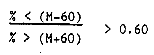
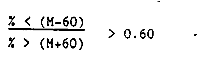
- the particle size distribution should be such that the ratio of the percent of small particles (particles less than the median (M) minus 60 microns) to the percent of large particles (particles greater than the median (M) plus 60 microns) is greater than 0.60.
- the filler is inorganic.
- the inorganic filler is a ceramic material having a purity of greater than or equal to 98%, most preferably greater than 98.5%.
- the inorganic filler is a plate-like ceramic powder.
- the thermal conductivity of the polymer matrix composite is greater than 10 W/m°K, preferably in the range of 10-20 W/m°K.
- the process for producing the polymer composition comprises selecting a polymer matrix and thermal conductive filler characterized as set forth above, mixing the materials under low shear conditions and curing the resulting composite (mixture) at an elevated temperature and pressure.
- novel composites of the present invention have shown a remarkably greater thermal conductivity compared to known polymer composites.
- the composites have greater ease of processing and because they contain inert fillers, reduce the fear of ionic migration in electronic applications. Due to the high thermal conductivity of the composites of the present invention, the life of the electronic components wherein these composites are utilized is significantly increased and catastrophic failure of the electronic components can be substantially avoided.
- the composition of the present invention comprises an inorganic filler and a polymer carrier or matrix.
- the inorganic filler is selected from ceramic materials such as boron nitride, aluminum nitride and silicon carbide.
- the filler be a plate-like or lamellar powder as opposed to spherical in form.
- the plate-like filler should have an aspect ratio of between 3-40, preferably 10-30, most preferably 15-25.
- the polymer carrier material may be either a thermoplastic or a thermosetting material.
- thermosetting materials include epoxies, silicones, phenolics, polyesters, polyimides and acrylonitriles.
- Thermoplastic materials such as polyethylene, acrylics, vinyls and fluorocarbons are envisioned as suitable for the practice of the invention.
- carrier materials must be stable at temperatures of -50°C to 150°C.
- the ceramic filler should be carefully characterized to satisfy the specific particle size distribution with a median particle size between 130 and 260 microns.
- the particle size distribution should be such that the ratio of the percent of small particles (particles less than the median (M) minus 60 microns) to the percent of large particles (particles greater than the median (M) plus 60 microns) is greater than 0.60. This can be stated arithmetically as follows: where % presents the weight percent of the particles above or below the described median particle size and M represents the median particle size in microns.
- the surface area of the thermal filler is less than 10 m2/g, preferably less than 5 m2/g. It has been found that the low surface area gives composites which have higher thermal conductivities.
- the ceramic filler should have a high degree of purity.
- the ceramic filler should be at least 98% pure, most preferably at least 98.5% pure.
- boron nitride powders are used as a ceramic filler, they should contain at least 98% boron and nitrogen with at most 2% impurities, most preferably 98.5% boron and nitrogen.
- the volume concentration of the ceramic filler in the composite is not particularly critical. Thermal conductivity can be optimized using 50 volume % filler to polymer matrix. However, a composite with 25 volume % filler has been demonstrated to have sufficiently good thermal conductivity in the practice of the present invention. Preferably, the volume % of filler in the composite can vary from 75 to 10%.
- the process of producing the polymer composite comprises selecting a polymer matrix and adding to the matrix a thermal conductive inorganic filler having a median particle size and size distribution as described previously.
- the resulting mixture is then mixed under low shear conditions which are defined for purpose of this invention as mixing at a speed insufficient to damage or destroy the original shape of the inorganic thermal conductive filler added to the polymer matrix.
- a suitable means for mixing under low shear conditions can be achieved by using a double planetary mixer manufactured by Ross Mixing Co. After the filler has been mixed with the polymer matrix the resulting composite is cured at an elevated temperature and pressure.
- the temperatures used in curing or processing the composites of the present invention will be governed by the polymer system used as the carrier or matrix and by the end use of the composite.
- an epoxy/boron nitride composite to be used as an adhesive for an electronic component would need a cure temperature between ambient and 300°C.
- a fluorocarbon/boron nitride composite to be used in a printing wiring board or substrate fabrication could withstand considerably higher processing temperatures (i.e. 450°C). It is envisioned in the practice of the present invention that the temperature for curing or processing of the composites can vary between 50°C to 500°C depending on the various polymer carriers used in the composite and the end use of the composite.
- the application of pressure during curing of the composite may be utilized advantageously to increase thermal conductivity.
- the use of at least 20 psi, preferably greater than 40 psi, has been utilized during curing of the composite.
- the epoxy Masterbond EP110F6 (manufactured by Masterbond Co.), was prepared according to manufacturer's directions. That is, 100 parts of resin (component A) was mixed with 200 parts of hardener (component B). 3.38 g of boron nitride powder A (see Table I for characterization) was dispersed in 1.50 grams of the epoxy under low shear conditions utilizing a double planetary mixer manufactured by Ross Mixing Co. The sample was cured in a cylindrical die with a diameter of 0.5" at 135°C and 40 psi for 2 hours. The cured rod was sliced into a disc ⁇ 2mm thick and analyzed by the laser-flash technique for thermal diffusivity.
- Example 1 The procedure of Example 1 was followed except Powder B was used. See Tables I and II below for the characterization of Powder B and the results obtained.
- Example 1 The procedure of Example 1 was followed except Powder C was used. See Tables I and II below for the characterization of Powder C and the results obtained.
- Example 1 The procedure of Example 1 was followed except Powder D was used. See Tables I and II below for the characterization of Powder D and the results obtained.
- Example 1 The procedure of Example 1 was followed except Powder E was used. See Tables I and II below for the characterization of Powder E and the results obtained.
- Example 1 The procedure of Example 1 was followed except Powder F was used. See Tables I and II below for the characterization of Powder F and the results obtained. TABLE II BORON NITRIDE/EPOXY COMPOSITE RESULTS Boron Nitride Powder Thermal Conductivity Watts/Meter °K Volume % Boron Nitride A 18.3 50 A 11.9 50 B 4.3 50 C 6.3 50 D 8.0 50 E 3.6 50 F 14.0 50
- the practice of the present invention provides a composite having extremely good thermal conductivity. It is a requirement of the composite material that the median particle size range between 130 to 260 microns and that the particle size distribution according to the above-described formula be greater than .60. In addition, the purity of the ceramic filler material should be greater than 98%, most preferably 98.5%.
Landscapes
- Engineering & Computer Science (AREA)
- Chemical & Material Sciences (AREA)
- Microelectronics & Electronic Packaging (AREA)
- Manufacturing & Machinery (AREA)
- Chemical Kinetics & Catalysis (AREA)
- Combustion & Propulsion (AREA)
- Thermal Sciences (AREA)
- Materials Engineering (AREA)
- Organic Chemistry (AREA)
- Physics & Mathematics (AREA)
- Compositions Of Macromolecular Compounds (AREA)
- Processes Of Treating Macromolecular Substances (AREA)
- Ceramic Products (AREA)
Abstract
Description
- This invention is directed to a thermally conductive material useful as a heat transfer material for electrical components. In particular, the present invention relates to a novel ceramic-polymer composition which may be used as an adhesive for attaching electrical components to printed circuit boards, high power components such as transistors to heat sinks, laminates, hybrid substrates for electrical components and, finally, encapsulating compositions for use in integrated circuits where dissipation of heat is a critical requirement of the encapsulant.
- The dramatic increase in circuit density in today's microcircuitry has lead to the attendant problem of heat generation. It is well known that the reliability of the microcircuit is directly affected by its ability to dissipate the heat generated. Electrical components which generate heat must have a means for heat removal in order to function properly. Numerous attempts to alleviate the problem of dissipation of heat have been made including encapsulating or attaching the electrical component to the substrate with a polymer material filled with a ceramic filler to aid in heat dissipation. Specific examples of these types of materials can be found in U.S. Patent 3,908,040 and U.S. Patent 4,265,775. Each of these patents disclose various polymer materials having heat dissipating ceramic fillers therein and their use as encapsulants or adhesives for electrical components. The present invention is directed to an improved thermally conductive polymer composite which is characterized by significant thermal conductive (heat dissipation) properties.
- It is the primary object of the present invention to provide a novel thermal conductive polymer composite which has good heat dissipation properties.
- It is another of the present invention to provide a novel thermal conductive composite having a thermal conductivity in the range of between 10 to 20 W/m°K.
- Additional objects and advantages of the invention will be set forth in part in the description which follows and in part will be obvious from the description or may be learned by practice of the invention. The objects and advantages of the invention may be realized and attained by means of the instrumentalities and combinations particularly pointed out in the appended claims.
- To achieve the foregoing objects and in accordance with the purpose of the present invention as embodied and broadly described herein, the thermally conductive polymer composition of the present invention comprises a mixture of a polymer material and a thermally conductive filler having a median particle size between the range of 130 to 260 microns. Moreover, the particle size distribution should be such that the ratio of the percent of small particles (particles less than the median (M) minus 60 microns) to the percent of large particles (particles greater than the median (M) plus 60 microns) is greater than 0.60. Preferably the filler is inorganic.
- In a preferred embodiment of the present invention, the inorganic filler is a ceramic material having a purity of greater than or equal to 98%, most preferably greater than 98.5%.
- In a further preferred embodiment the inorganic filler is a plate-like ceramic powder.
- In a still further preferred embodiment of the present invention, the thermal conductivity of the polymer matrix composite is greater than 10 W/m°K, preferably in the range of 10-20 W/m°K.
- In another embodiment of the present invention, the process for producing the polymer composition comprises selecting a polymer matrix and thermal conductive filler characterized as set forth above, mixing the materials under low shear conditions and curing the resulting composite (mixture) at an elevated temperature and pressure.
- The novel composites of the present invention have shown a remarkably greater thermal conductivity compared to known polymer composites. In addition, the composites have greater ease of processing and because they contain inert fillers, reduce the fear of ionic migration in electronic applications. Due to the high thermal conductivity of the composites of the present invention, the life of the electronic components wherein these composites are utilized is significantly increased and catastrophic failure of the electronic components can be substantially avoided.
- Reference will now be made in detail to the present preferred embodiments of the invention.
- The composition of the present invention comprises an inorganic filler and a polymer carrier or matrix. Preferably, the inorganic filler is selected from ceramic materials such as boron nitride, aluminum nitride and silicon carbide. However, it should be understood that other thermal conductive fillers such as silver may be utilized in the practice of the present invention. It is further preferred that the filler be a plate-like or lamellar powder as opposed to spherical in form. Most preferably, the plate-like filler should have an aspect ratio of between 3-40, preferably 10-30, most preferably 15-25.
- The polymer carrier material may be either a thermoplastic or a thermosetting material. Typical examples of thermosetting materials include epoxies, silicones, phenolics, polyesters, polyimides and acrylonitriles. Thermoplastic materials such as polyethylene, acrylics, vinyls and fluorocarbons are envisioned as suitable for the practice of the invention. Typically, carrier materials must be stable at temperatures of -50°C to 150°C.
- The ceramic filler should be carefully characterized to satisfy the specific particle size distribution with a median particle size between 130 and 260 microns. To achieve the unique results of the present invention, the particle size distribution should be such that the ratio of the percent of small particles (particles less than the median (M) minus 60 microns) to the percent of large particles (particles greater than the median (M) plus 60 microns) is greater than 0.60. This can be stated arithmetically as follows:
- In a further preferred embodiment of the present invention, the surface area of the thermal filler is less than 10 m²/g, preferably less than 5 m²/g. It has been found that the low surface area gives composites which have higher thermal conductivities.
- In a still further preferred embodiment of the present invention, the ceramic filler should have a high degree of purity. In particular, the ceramic filler should be at least 98% pure, most preferably at least 98.5% pure. For example, if boron nitride powders are used as a ceramic filler, they should contain at least 98% boron and nitrogen with at most 2% impurities, most preferably 98.5% boron and nitrogen.
- The volume concentration of the ceramic filler in the composite is not particularly critical. Thermal conductivity can be optimized using 50 volume % filler to polymer matrix. However, a composite with 25 volume % filler has been demonstrated to have sufficiently good thermal conductivity in the practice of the present invention. Preferably, the volume % of filler in the composite can vary from 75 to 10%.
- In a further embodiment of the present invention, the process of producing the polymer composite comprises selecting a polymer matrix and adding to the matrix a thermal conductive inorganic filler having a median particle size and size distribution as described previously. The resulting mixture is then mixed under low shear conditions which are defined for purpose of this invention as mixing at a speed insufficient to damage or destroy the original shape of the inorganic thermal conductive filler added to the polymer matrix. A suitable means for mixing under low shear conditions can be achieved by using a double planetary mixer manufactured by Ross Mixing Co. After the filler has been mixed with the polymer matrix the resulting composite is cured at an elevated temperature and pressure.
- The temperatures used in curing or processing the composites of the present invention will be governed by the polymer system used as the carrier or matrix and by the end use of the composite. For example, an epoxy/boron nitride composite to be used as an adhesive for an electronic component would need a cure temperature between ambient and 300°C. On the other hand, a fluorocarbon/boron nitride composite to be used in a printing wiring board or substrate fabrication could withstand considerably higher processing temperatures (i.e. 450°C). It is envisioned in the practice of the present invention that the temperature for curing or processing of the composites can vary between 50°C to 500°C depending on the various polymer carriers used in the composite and the end use of the composite.
- The application of pressure during curing of the composite may be utilized advantageously to increase thermal conductivity. For example, the use of at least 20 psi, preferably greater than 40 psi, has been utilized during curing of the composite.
- The addition of other additives such as conventional plasticizers, swelling agents, flexibilizers, coupling agents, etc. can be used in conjunction with the ceramic filler to provide characteristics as needed for specific applications. Selection of these conventional materials is well known in the art and does not form a part of the present invention. To further illustrate the practice of the present invention, the following examples are presented.
- The epoxy, Masterbond EP110F6 (manufactured by Masterbond Co.), was prepared according to manufacturer's directions. That is, 100 parts of resin (component A) was mixed with 200 parts of hardener (component B). 3.38 g of boron nitride powder A (see Table I for characterization) was dispersed in 1.50 grams of the epoxy under low shear conditions utilizing a double planetary mixer manufactured by Ross Mixing Co. The sample was cured in a cylindrical die with a diameter of 0.5" at 135°C and 40 psi for 2 hours. The cured rod was sliced into a disc ∼2mm thick and analyzed by the laser-flash technique for thermal diffusivity.
- From this thermal conductivity was then calculated using specific heat and density. See Table II, Powder A, 50 volume % for the results.
- The procedure of Example 1 was followed except Powder B was used. See Tables I and II below for the characterization of Powder B and the results obtained.
- The procedure of Example 1 was followed except Powder C was used. See Tables I and II below for the characterization of Powder C and the results obtained.
- The procedure of Example 1 was followed except Powder D was used. See Tables I and II below for the characterization of Powder D and the results obtained.
- The procedure of Example 1 was followed except Powder E was used. See Tables I and II below for the characterization of Powder E and the results obtained.
- The procedure of Example 1 was followed except Powder F was used. See Tables I and II below for the characterization of Powder F and the results obtained.

TABLE II BORON NITRIDE/EPOXY COMPOSITE RESULTS Boron Nitride Powder Thermal Conductivity Watts/Meter °K Volume % Boron Nitride A 18.3 50 A 11.9 50 B 4.3 50 C 6.3 50 D 8.0 50 E 3.6 50 F 14.0 50 - As can be readily seen from the results set forth in Tables I and II above, the practice of the present invention provides a composite having extremely good thermal conductivity. It is a requirement of the composite material that the median particle size range between 130 to 260 microns and that the particle size distribution according to the above-described formula be greater than .60. In addition, the purity of the ceramic filler material should be greater than 98%, most preferably 98.5%.
- The foregoing description of the preferred embodiments of the present invention have been presented for purposes of illustration and description. They are not intended to be exhaustive or to limit the invention to the precise form disclosed, and obviously many modifications and variations are possible in light of the above teachings. The embodiments are chosen are described in order to best explain the principles of the invention in its practical applications to thereby enable others skilled in the art to best utilize the invention in various embodiments and with various modifications as are suited to the particle use contemplated. It is intended that the scope of the invention be defined by the claims appended hereto.
Claims (10)


Applications Claiming Priority (2)
| Application Number | Priority Date | Filing Date | Title |
|---|---|---|---|
| US13578587A | 1987-12-21 | 1987-12-21 | |
| US135785 | 1987-12-21 |
Publications (2)
| Publication Number | Publication Date |
|---|---|
| EP0322165A1 true EP0322165A1 (en) | 1989-06-28 |
| EP0322165B1 EP0322165B1 (en) | 1992-08-05 |
Family
ID=22469655
Family Applications (1)
| Application Number | Title | Priority Date | Filing Date |
|---|---|---|---|
| EP88311962A Expired - Lifetime EP0322165B1 (en) | 1987-12-21 | 1988-12-16 | Thermally conductive ceramic/polymer composites |
Country Status (6)
| Country | Link |
|---|---|
| EP (1) | EP0322165B1 (en) |
| JP (1) | JPH02263847A (en) |
| KR (1) | KR970006227B1 (en) |
| CA (1) | CA1331245C (en) |
| DE (1) | DE3873503T2 (en) |
| ES (1) | ES2034273T3 (en) |
Cited By (16)
| Publication number | Priority date | Publication date | Assignee | Title |
|---|---|---|---|---|
| FR2694839A1 (en) * | 1992-08-14 | 1994-02-18 | Protex Manuf Prod Chimiq | Use of brown corundum as a thermally conductive filler in polymeric compositions, in particular electrically insulating coating compositions. |
| EP0561048A3 (en) * | 1992-03-16 | 1995-03-01 | Hughes Aircraft Co | |
| WO1995022175A1 (en) * | 1994-02-14 | 1995-08-17 | W.L. Gore & Associates, Inc. | Improved thermally conductive interface |
| US5591034A (en) * | 1994-02-14 | 1997-01-07 | W. L. Gore & Associates, Inc. | Thermally conductive adhesive interface |
| US5738936A (en) * | 1996-06-27 | 1998-04-14 | W. L. Gore & Associates, Inc. | Thermally conductive polytetrafluoroethylene article |
| EP0928027A3 (en) * | 1998-01-05 | 2000-03-15 | Nitto Denko Corporation | Heat-conductive and pressure-sensitive adhesive sheets and method for fixing electronic parts to heat-radiating members with the use of the same |
| WO2001096458A1 (en) * | 2000-06-16 | 2001-12-20 | Siemens Aktiengesellschaft | Filling material for heat conducting plastics, heat conducting plastic and method for the production thereof |
| WO2002013261A3 (en) * | 2000-08-07 | 2003-07-10 | Formfactor Inc | Heat spreading die cover |
| WO2004081139A1 (en) * | 2003-03-12 | 2004-09-23 | National Starch And Chemical Investment Holding Corporation | Electronic device containing thermal interface material |
| EP1182768A3 (en) * | 2000-08-21 | 2004-12-15 | Vlt Corporation | Power converter assembly |
| WO2004081972A3 (en) * | 2003-03-10 | 2005-04-28 | Osram Opto Semiconductors Gmbh | Housing body, optoelectronic component with a housing body of this type, and plastic housing material |
| WO2006023860A3 (en) * | 2004-08-23 | 2006-06-29 | Gen Electric | Thermally conductive composition and method for preparing the same |
| EP1887033A1 (en) * | 2006-08-10 | 2008-02-13 | National Starch and Chemical Investment Holding Corporation | Thermally conductive material |
| US7976941B2 (en) | 1999-08-31 | 2011-07-12 | Momentive Performance Materials Inc. | Boron nitride particles of spherical geometry and process for making thereof |
| ITRN20130032A1 (en) * | 2013-08-10 | 2015-02-11 | Rebernig Supervisioni Srl | ELECTRICAL AND / OR ELECTRONIC DEVICE INCLUDING AT LEAST A PRINTED CIRCUIT. |
| US9550888B2 (en) | 1999-08-31 | 2017-01-24 | Momentive Performance Materials Inc. | Low viscosity filler composition of boron nitride particles of spherical geometry and process |
Families Citing this family (2)
| Publication number | Priority date | Publication date | Assignee | Title |
|---|---|---|---|---|
| US6121637A (en) * | 1997-10-03 | 2000-09-19 | Rohm Co., Ltd. | Semiconductor light emitting device with increased luminous power |
| DE102010005020B4 (en) * | 2010-01-19 | 2019-12-12 | Continental Automotive Gmbh | Use of a shaped body made of a thermally conductive composite material for heat dissipation |
Citations (4)
| Publication number | Priority date | Publication date | Assignee | Title |
|---|---|---|---|---|
| US3972821A (en) * | 1973-04-30 | 1976-08-03 | Amchem Products, Inc. | Heat transfer composition and method of making |
| FR2307351A1 (en) * | 1975-04-11 | 1976-11-05 | Sola Basic Ind Inc | ELASTOMERIC MATERIAL FOR STRAIN REDUCTION AND DEVICES MANUFACTURED WITH IT |
| US4210774A (en) * | 1977-06-16 | 1980-07-01 | Electric Power Research Institute, Inc. | Filled polymer electrical insulator |
| GB2152060A (en) * | 1983-12-02 | 1985-07-31 | Osaka Soda Co Ltd | Electrically conductive adhesive composition |
-
1988
- 1988-12-15 CA CA000585982A patent/CA1331245C/en not_active Expired - Fee Related
- 1988-12-16 EP EP88311962A patent/EP0322165B1/en not_active Expired - Lifetime
- 1988-12-16 DE DE8888311962T patent/DE3873503T2/en not_active Expired - Lifetime
- 1988-12-16 ES ES198888311962T patent/ES2034273T3/en not_active Expired - Lifetime
- 1988-12-21 KR KR1019880017140A patent/KR970006227B1/en not_active Expired - Fee Related
- 1988-12-21 JP JP63323196A patent/JPH02263847A/en active Pending
Patent Citations (4)
| Publication number | Priority date | Publication date | Assignee | Title |
|---|---|---|---|---|
| US3972821A (en) * | 1973-04-30 | 1976-08-03 | Amchem Products, Inc. | Heat transfer composition and method of making |
| FR2307351A1 (en) * | 1975-04-11 | 1976-11-05 | Sola Basic Ind Inc | ELASTOMERIC MATERIAL FOR STRAIN REDUCTION AND DEVICES MANUFACTURED WITH IT |
| US4210774A (en) * | 1977-06-16 | 1980-07-01 | Electric Power Research Institute, Inc. | Filled polymer electrical insulator |
| GB2152060A (en) * | 1983-12-02 | 1985-07-31 | Osaka Soda Co Ltd | Electrically conductive adhesive composition |
Cited By (20)
| Publication number | Priority date | Publication date | Assignee | Title |
|---|---|---|---|---|
| EP0561048A3 (en) * | 1992-03-16 | 1995-03-01 | Hughes Aircraft Co | |
| FR2694839A1 (en) * | 1992-08-14 | 1994-02-18 | Protex Manuf Prod Chimiq | Use of brown corundum as a thermally conductive filler in polymeric compositions, in particular electrically insulating coating compositions. |
| WO1995022175A1 (en) * | 1994-02-14 | 1995-08-17 | W.L. Gore & Associates, Inc. | Improved thermally conductive interface |
| US5545473A (en) * | 1994-02-14 | 1996-08-13 | W. L. Gore & Associates, Inc. | Thermally conductive interface |
| US5591034A (en) * | 1994-02-14 | 1997-01-07 | W. L. Gore & Associates, Inc. | Thermally conductive adhesive interface |
| US5738936A (en) * | 1996-06-27 | 1998-04-14 | W. L. Gore & Associates, Inc. | Thermally conductive polytetrafluoroethylene article |
| EP0928027A3 (en) * | 1998-01-05 | 2000-03-15 | Nitto Denko Corporation | Heat-conductive and pressure-sensitive adhesive sheets and method for fixing electronic parts to heat-radiating members with the use of the same |
| US6194063B1 (en) | 1998-01-05 | 2001-02-27 | Nitto Denko Corporation | Heat-conductive and pressure-sensitive adhesive sheets and method for fixing electronic parts to heat-radiating members with the use of the same |
| US7976941B2 (en) | 1999-08-31 | 2011-07-12 | Momentive Performance Materials Inc. | Boron nitride particles of spherical geometry and process for making thereof |
| US9079801B2 (en) | 1999-08-31 | 2015-07-14 | Momentive Performance Materials Inc. | Boron nitride particles of spherical geometry and process of making |
| US9550888B2 (en) | 1999-08-31 | 2017-01-24 | Momentive Performance Materials Inc. | Low viscosity filler composition of boron nitride particles of spherical geometry and process |
| WO2001096458A1 (en) * | 2000-06-16 | 2001-12-20 | Siemens Aktiengesellschaft | Filling material for heat conducting plastics, heat conducting plastic and method for the production thereof |
| WO2002013261A3 (en) * | 2000-08-07 | 2003-07-10 | Formfactor Inc | Heat spreading die cover |
| EP1182768A3 (en) * | 2000-08-21 | 2004-12-15 | Vlt Corporation | Power converter assembly |
| WO2004081972A3 (en) * | 2003-03-10 | 2005-04-28 | Osram Opto Semiconductors Gmbh | Housing body, optoelectronic component with a housing body of this type, and plastic housing material |
| WO2004081139A1 (en) * | 2003-03-12 | 2004-09-23 | National Starch And Chemical Investment Holding Corporation | Electronic device containing thermal interface material |
| WO2006023860A3 (en) * | 2004-08-23 | 2006-06-29 | Gen Electric | Thermally conductive composition and method for preparing the same |
| EP1887033A1 (en) * | 2006-08-10 | 2008-02-13 | National Starch and Chemical Investment Holding Corporation | Thermally conductive material |
| ITRN20130032A1 (en) * | 2013-08-10 | 2015-02-11 | Rebernig Supervisioni Srl | ELECTRICAL AND / OR ELECTRONIC DEVICE INCLUDING AT LEAST A PRINTED CIRCUIT. |
| WO2015022607A1 (en) * | 2013-08-10 | 2015-02-19 | Rebernig Supervisioni Srl | Electrical and / or electronic device comprising at least one printed circuit |
Also Published As
| Publication number | Publication date |
|---|---|
| KR890011509A (en) | 1989-08-14 |
| JPH02263847A (en) | 1990-10-26 |
| EP0322165B1 (en) | 1992-08-05 |
| DE3873503T2 (en) | 1992-12-24 |
| CA1331245C (en) | 1994-08-02 |
| ES2034273T3 (en) | 1993-04-01 |
| DE3873503D1 (en) | 1992-09-10 |
| KR970006227B1 (en) | 1997-04-24 |
Similar Documents
| Publication | Publication Date | Title |
|---|---|---|
| US5011872A (en) | Thermally conductive ceramic/polymer composites | |
| EP0322165B1 (en) | Thermally conductive ceramic/polymer composites | |
| CA2207114C (en) | Semisolid thermal interface with low flow resistance | |
| US6197859B1 (en) | Thermally conductive interface pads for electronic devices | |
| US5781412A (en) | Conductive cooling of a heat-generating electronic component using a cured-in-place, thermally-conductive interlayer having a filler of controlled particle size | |
| US4882455A (en) | Electronic circuit substrates | |
| US4571610A (en) | Semiconductor device having electrically insulating substrate of SiC | |
| US6822018B2 (en) | Thermally-conductive electrically-insulating polymer-base material | |
| WO2018181606A1 (en) | Heat-conducting member and heat-dissipating structure including said heat-conducting member | |
| EP3496139B1 (en) | Heat dissipation structure for electric circuit device | |
| CN105263886A (en) | Resin impregnated boron nitride sintered body and its application | |
| JP2883787B2 (en) | Substrate for power semiconductor device | |
| JPH1126661A (en) | Heat radiation spacer | |
| KR102403680B1 (en) | Polysiloxane composite containing ceramic beads of various sizes and method for manufacturing the same | |
| KR20100133449A (en) | Thermally Enhanced Electrical Insulation Paste | |
| US6649325B1 (en) | Thermally conductive dielectric mounts for printed circuitry and semi-conductor devices and method of preparation | |
| EP0790762A2 (en) | Conductive cooling of a heat-generating electronic component | |
| JPH0644824A (en) | Insulating material and circuit substrate using the same | |
| JPH07162177A (en) | Radiator | |
| KR100566551B1 (en) | Small Particle Adhesive Compositions for Microelectronic Devices | |
| JPS63307748A (en) | Resin material | |
| US5945470A (en) | Ceramic-polymer composite material and its use in microelectronics packaging | |
| JP3255814B2 (en) | Metal-based circuit board and module using the same | |
| JP3683067B2 (en) | Aluminum nitride sintered body | |
| Asai et al. | Titanium nitride-molybdenum metallizing method for aluminum nitride |
Legal Events
| Date | Code | Title | Description |
|---|---|---|---|
| PUAI | Public reference made under article 153(3) epc to a published international application that has entered the european phase |
Free format text: ORIGINAL CODE: 0009012 |
|
| AK | Designated contracting states |
Kind code of ref document: A1 Designated state(s): BE DE ES FR GB IT NL |
|
| 17P | Request for examination filed |
Effective date: 19891129 |
|
| 17Q | First examination report despatched |
Effective date: 19910531 |
|
| GRAA | (expected) grant |
Free format text: ORIGINAL CODE: 0009210 |
|
| AK | Designated contracting states |
Kind code of ref document: B1 Designated state(s): BE DE ES FR GB IT NL |
|
| ITF | It: translation for a ep patent filed | ||
| REF | Corresponds to: |
Ref document number: 3873503 Country of ref document: DE Date of ref document: 19920910 |
|
| ET | Fr: translation filed | ||
| REG | Reference to a national code |
Ref country code: ES Ref legal event code: FG2A Ref document number: 2034273 Country of ref document: ES Kind code of ref document: T3 |
|
| PLBE | No opposition filed within time limit |
Free format text: ORIGINAL CODE: 0009261 |
|
| STAA | Information on the status of an ep patent application or granted ep patent |
Free format text: STATUS: NO OPPOSITION FILED WITHIN TIME LIMIT |
|
| 26N | No opposition filed | ||
| PGFP | Annual fee paid to national office [announced via postgrant information from national office to epo] |
Ref country code: FR Payment date: 19961115 Year of fee payment: 9 |
|
| PGFP | Annual fee paid to national office [announced via postgrant information from national office to epo] |
Ref country code: NL Payment date: 19961120 Year of fee payment: 9 |
|
| PGFP | Annual fee paid to national office [announced via postgrant information from national office to epo] |
Ref country code: DE Payment date: 19961122 Year of fee payment: 9 |
|
| PGFP | Annual fee paid to national office [announced via postgrant information from national office to epo] |
Ref country code: BE Payment date: 19961126 Year of fee payment: 9 |
|
| PGFP | Annual fee paid to national office [announced via postgrant information from national office to epo] |
Ref country code: GB Payment date: 19961128 Year of fee payment: 9 |
|
| PGFP | Annual fee paid to national office [announced via postgrant information from national office to epo] |
Ref country code: ES Payment date: 19961216 Year of fee payment: 9 |
|
| PG25 | Lapsed in a contracting state [announced via postgrant information from national office to epo] |
Ref country code: GB Free format text: LAPSE BECAUSE OF NON-PAYMENT OF DUE FEES Effective date: 19971216 |
|
| PG25 | Lapsed in a contracting state [announced via postgrant information from national office to epo] |
Ref country code: FR Free format text: THE PATENT HAS BEEN ANNULLED BY A DECISION OF A NATIONAL AUTHORITY Effective date: 19971231 Ref country code: BE Free format text: LAPSE BECAUSE OF NON-PAYMENT OF DUE FEES Effective date: 19971231 |
|
| BERE | Be: lapsed |
Owner name: THE STANDARD OIL CY Effective date: 19971231 |
|
| PG25 | Lapsed in a contracting state [announced via postgrant information from national office to epo] |
Ref country code: NL Free format text: LAPSE BECAUSE OF NON-PAYMENT OF DUE FEES Effective date: 19980701 |
|
| GBPC | Gb: european patent ceased through non-payment of renewal fee |
Effective date: 19971216 |
|
| NLV4 | Nl: lapsed or anulled due to non-payment of the annual fee |
Effective date: 19980701 |
|
| PG25 | Lapsed in a contracting state [announced via postgrant information from national office to epo] |
Ref country code: DE Free format text: LAPSE BECAUSE OF NON-PAYMENT OF DUE FEES Effective date: 19980901 |
|
| REG | Reference to a national code |
Ref country code: FR Ref legal event code: ST |
|
| PG25 | Lapsed in a contracting state [announced via postgrant information from national office to epo] |
Ref country code: ES Free format text: LAPSE BECAUSE OF NON-PAYMENT OF DUE FEES Effective date: 19981217 |
|
| REG | Reference to a national code |
Ref country code: ES Ref legal event code: FD2A Effective date: 19990114 |
|
| PG25 | Lapsed in a contracting state [announced via postgrant information from national office to epo] |
Ref country code: IT Free format text: LAPSE BECAUSE OF NON-PAYMENT OF DUE FEES;WARNING: LAPSES OF ITALIAN PATENTS WITH EFFECTIVE DATE BEFORE 2007 MAY HAVE OCCURRED AT ANY TIME BEFORE 2007. THE CORRECT EFFECTIVE DATE MAY BE DIFFERENT FROM THE ONE RECORDED. Effective date: 20051216 |
|
| PGFP | Annual fee paid to national office [announced via postgrant information from national office to epo] |
Ref country code: IT Payment date: 20071210 Year of fee payment: 20 |
|
| PGRI | Patent reinstated in contracting state [announced from national office to epo] |
Ref country code: IT Effective date: 20091201 |