EP0324839B1 - Site d'injection pour dispositif de perfusion - Google Patents
Site d'injection pour dispositif de perfusion Download PDFInfo
- Publication number
- EP0324839B1 EP0324839B1 EP88906810A EP88906810A EP0324839B1 EP 0324839 B1 EP0324839 B1 EP 0324839B1 EP 88906810 A EP88906810 A EP 88906810A EP 88906810 A EP88906810 A EP 88906810A EP 0324839 B1 EP0324839 B1 EP 0324839B1
- Authority
- EP
- European Patent Office
- Prior art keywords
- injection site
- stopper
- housing
- valve
- ledge
- Prior art date
- Legal status (The legal status is an assumption and is not a legal conclusion. Google has not performed a legal analysis and makes no representation as to the accuracy of the status listed.)
- Expired
Links
- 238000002347 injection Methods 0.000 title claims abstract description 77
- 239000007924 injection Substances 0.000 title claims abstract description 77
- 238000001802 infusion Methods 0.000 title 1
- 230000006835 compression Effects 0.000 claims abstract description 6
- 238000007906 compression Methods 0.000 claims abstract description 6
- 239000012530 fluid Substances 0.000 claims description 13
- 238000003780 insertion Methods 0.000 claims description 4
- 230000037431 insertion Effects 0.000 claims description 4
- 238000000465 moulding Methods 0.000 claims description 4
- 238000010276 construction Methods 0.000 claims description 3
- 239000003182 parenteral nutrition solution Substances 0.000 claims description 3
- 239000003978 infusion fluid Substances 0.000 abstract description 5
- 239000003814 drug Substances 0.000 description 8
- 229940079593 drug Drugs 0.000 description 8
- 238000001990 intravenous administration Methods 0.000 description 6
- 239000000243 solution Substances 0.000 description 6
- 230000008901 benefit Effects 0.000 description 4
- 239000004599 antimicrobial Substances 0.000 description 3
- 239000004816 latex Substances 0.000 description 3
- 229920000126 latex Polymers 0.000 description 3
- 239000000356 contaminant Substances 0.000 description 2
- LFQSCWFLJHTTHZ-UHFFFAOYSA-N Ethanol Chemical compound CCO LFQSCWFLJHTTHZ-UHFFFAOYSA-N 0.000 description 1
- 241000405070 Percophidae Species 0.000 description 1
- VRDIULHPQTYCLN-UHFFFAOYSA-N Prothionamide Chemical compound CCCC1=CC(C(N)=S)=CC=N1 VRDIULHPQTYCLN-UHFFFAOYSA-N 0.000 description 1
- 239000000853 adhesive Substances 0.000 description 1
- 230000001070 adhesive effect Effects 0.000 description 1
- 238000004140 cleaning Methods 0.000 description 1
- 150000001875 compounds Chemical class 0.000 description 1
- 239000003085 diluting agent Substances 0.000 description 1
- 229920001971 elastomer Polymers 0.000 description 1
- 238000010438 heat treatment Methods 0.000 description 1
- 239000007788 liquid Substances 0.000 description 1
- 230000014759 maintenance of location Effects 0.000 description 1
- 239000000463 material Substances 0.000 description 1
- 238000000034 method Methods 0.000 description 1
- 238000007911 parenteral administration Methods 0.000 description 1
- 239000013618 particulate matter Substances 0.000 description 1
- 238000010926 purge Methods 0.000 description 1
- 238000010079 rubber tapping Methods 0.000 description 1
- 230000001954 sterilising effect Effects 0.000 description 1
- 238000004659 sterilization and disinfection Methods 0.000 description 1
- 230000000153 supplemental effect Effects 0.000 description 1
- 238000002560 therapeutic procedure Methods 0.000 description 1
- 238000011144 upstream manufacturing Methods 0.000 description 1
- 125000000391 vinyl group Chemical group [H]C([*])=C([H])[H] 0.000 description 1
- 229920002554 vinyl polymer Polymers 0.000 description 1
- 238000003466 welding Methods 0.000 description 1
Images


Classifications
-
- A—HUMAN NECESSITIES
- A61—MEDICAL OR VETERINARY SCIENCE; HYGIENE
- A61M—DEVICES FOR INTRODUCING MEDIA INTO, OR ONTO, THE BODY; DEVICES FOR TRANSDUCING BODY MEDIA OR FOR TAKING MEDIA FROM THE BODY; DEVICES FOR PRODUCING OR ENDING SLEEP OR STUPOR
- A61M39/00—Tubes, tube connectors, tube couplings, valves, access sites or the like, specially adapted for medical use
- A61M39/02—Access sites
- A61M39/04—Access sites having pierceable self-sealing members
Definitions
- This invention relates to a self-priming injection site. More particularly, this invention relates to a combination injection site and check valve for use in a parenteral solution administration apparatus whereby the apparatus is constructed so that the fluid flowing through the check valve automatically primes the injection site.
- injection sites are generally ′Y′ shaped with one of the top arms of the ′Y′ being covered by a sleeve stopper formed of a latex compound.
- the sleeve stopper known in the prior art surrounds both the inside and the outside of the upper portion of the hollow arm.
- the sleeve stopper has a center that extends across the hollow arm of the injection site to prevent contaminants from entering the intravenous administration set.
- the closed center surface is generally located adjacent to the end of the hollow arm.
- the sleeve stopper may be damaged, rearranged, or even removed from the injection site.
- the sleeve-type stopper is particularly susceptible to being pulled from the injection site by large gauge needles since the sleeve-type stopper depends solely on the friction between itself and the arm of the injection site to retain the stopper in proper position. Since the friction alone is often insufficient, a vinyl heat seal band may be placed around the outside of the sleeve stopper and the adjacent portion of the arm. Although the heat seal band has improved the retention of the stopper in the arm, the results have still not been totally satisfactory.
- the stoppers are generally formed of latex or a similar material that substantially reseals upon the needle being removed. However, repeated piercings damage the stopper, especially piercings done in such a manner that they create substantially larger openings. Once the stopper has been damaged by piercing, the stopper develops an even greater propensity to being moved from its proper position.
- the removal of the stopper from the injection site causes an assortment of problems including fluids leaking from the administration set and the introduction of contaminants and air into the intravenous solution.
- the problem of stoppers that do not remain in their proper position on the injection site is particularly troublesome since the injection site is not independently removable from the administration set.
- the entire administration set must be changed to allow a new injection site to be put into place. It would be an advantage to provide an injection site which can withstand a large number of needle piercings and removals even when subjected to high pressures often associated with injections from small syringes, which may exceed 8.5 ⁇ 105 Pa (125 p.s.i.).
- US-A-4294249 and EP-A-0109903 each disclose an injection site having a disc-shaped stopper positioned between a top of a housing and an O-shaped ledge in the housing, the top having a central opening.
- the top and the ledge are on separate parts secured together, whereas in US-A-4294249, the top and ledge are parts of a single moulding, the top being swaged over the edge of the stopper.
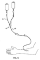
- the injection site of the instant invention can be seen by reference to the figures.
- the injection site indicated generally as 10, includes a housing, a stopper 14, and a valve 16.
- the injection site 10 is connected between tubing 18 and tubing 20 in an apparatus for administering a parenteral solution to a patient.
- the injection site constitutes a portion of the passageway of the intravenous fluid continually administered to the patient.
- a syringe or other injection apparatus is used to insert medication into the intravenous fluid.
- the needle is inserted and then withdrawn through stopper 14. Since the intravenous solution may be administered to the patient for lengthy periods of time, it is desirable to have a stopper that can withstand numerous piercings and removals of the needle, even under high pressure.
- Housing 12 may be a combination housing of a stopper housing 24 and valve housing or second housing 26, as shown in Figure 4, or may be a single housing as shown in Figure 6.
- the stopper housing or stopper portion 24 includes an approximately cylindrical portion 28, a top 30, an intermediate ledge 34, and a cone-shaped outlet portion 32. Cone-shaped outlet portion 32 helps deflect a needle into the center of the injection site to prevent the needle from piercing the sidewall of the injection site.
- Top 30 has an open center 38, while the ledge 34, which extends the entire 360° around the circumference of cylindrical portion 28, has an upwardly turned lip 40.
- the stopper 14 is approximately disc-shaped with its bottom surface having an annular groove 42 that receives ledge lip 40.
- Top 30 and ledge 34 hold stopper 14 in vertical and/or diametric compression to securely retain the stopper within the housing 12.
- Groove 42 creates an ear 44 around the circumference of the stopper 14. At least one dimension of the ear 44, such as the height, must be larger than the distance from the lip 40 to the top 30 to deter the repositioning or removal of the stopper when the needle is inserted and removed therefrom.
- the stopper Because the stopper is held in compression, its center 46 extends through the open center 38 of the housing. Raised center 46 facilitates the sterilization of the stopper, by providing easier accessibility for wiping with an anti-microbial agent, such as isopropal alcohol, with abrasive action.
- an anti-microbial agent such as isopropal alcohol
- Prior art injeciton sites having a stopper that is recessed below the remainder of the top of the injection site allow the anti-microbial agent to accumulate in a puddle on the top of the stopper. Particulate matter may also collect on the top of the stopper, and may be transmitted inside the injection site to the I.V. solution when a needle pierces the stopper.
- the raised or flush stopper design of the instant invention permits a clean drain of the anti microbial agent from the stopper, as well as facilitating the cleaning of the stopper.
- Raised center 46 has an embossed ring 48 that defines the preferred target area for insertion of the needle.
- a needle inserted within the embossed ring 48 exerts a force that is small enough that it generally does not reposition or remove the stopper from the housing.
- the target area is at least 3.8 mm (.15 inches in diameter), large enough to accept large bore needles, such as 16 or 18 gauge needles, and multiple simultaneous needles.
- the stopper housing 24 is molded as one unit. Immediately after molding, the top 30 of the housing is a vertical extension of the sides 50 of the cylindrical portion 28, as shown in Figure 5. After the stopper 14 is positioned on the ledge 34, the top edge of the cylinder sides 50 is bent inwards to form the top 30 either by ultrasonic deformation, by heating or by cold forming.
- the unitary molded housing holding stopper 14 in compression provides for lower cost, easier assembly and more stable assembly dimensions. Because the dimensions are more precise, the performance of the injection site is more reliable.
- the stopper housing 34 has an arm portion 54 joined to the cone-shaped outlet portion 32 immediately below ledge 34. Arm portion 54 provides for the main flow of fluid through the injection site. In the embodiment of the invention shown in Figures 1-5, the arm portion includes an enlarged section 54 that houses the valve 16.
- the valve in the embodiment shown is a duckbill type as will be described briefly herein and is described in more detail in U.S. Patent No. 4,566,493. A variety of other valves may also be used.
- a valve housing portion 26 is joined to the stopper housing 24 by one of a variety of methods. Adhesive may be applied between the two parts or ultrasonic welding may be used to cause the two parts to merge together.
- Valve 16 includes sides 56 extending to an annular collar 58. Valve sides 56 are positioned at an angle to form a slit 60 through which the fluid passes. The sides 56 are connected to one another through curved walls 62. Valve 16 also has tabs 64 positioned on the sides 56 adjacent the annular collar 58. The end of the valve at slit 60 is positioned very close to cone shaped outlet portion 32 of the housing, approximately 7 mm (.272 inches) from the end of the valve to the outlet passageway in the embodiment described herein.
- the close proximity of the two components prevents any retrograde flow up the I.V. tubing. This is important for drugs that require minimum diluent or that must be administered quickly to the patient. In particular, viscous highly dense drugs that flow up the I.V. tubing require considerable time and fluid for purging the drug out of the tubing.
- the present design also minimizes the stagnant area where drugs can collect, to reduce the portion of the drug that is not administered to the patient.
- Enlarged section 52 of the housing includes a flange 70 that surrounds and mates with the annular collar 58 of valve 16, while valve tabs 64 are received in notches 68 of the arm portion 54 of the housing. This arrangement helps to ensure that valve 16 does not twist within the housing. Since the clearance between valve sides 56 and sides 66 of the housing arm protion is very small, any twisting of valve 16 within the housing would disturb the proper operation of the valve.
- Valve housing 26 includes a sleeve 72 that surrounds the flange 70 of the housing arm portion. Passageway 74 of valve housing portion 26 includes an approximately right angle turn. Fluid through the valve flows vertically downward through passageway 74, then horizontally through arm portion 54, then downward again through cone-shaped outlet 32. Thus, the tubing attached to the valve housing and to the outlet of the stopper housing 24 are approximately parallel to one another. Since this tubing generally hangs vertically, stopper 14 will generally be positioned on the top of the injection site where it is easily accessible to medical personnel, as shown in the figures. The vertical inlet of valve housing 26 has its outer edge positioned at least.75 inches from the center of stopper 14. This allows for easy access with the large bore needles and multiple simultaneous needles, as discussed above.
- the intravenous solution As the intravenous solution enters the valve housing 26, it makes an approximately right angle turn as shown in the embodiment of Figures 1-5, moves through the valve and directly across the bottom of the housing ledge 34 and across the bottom of the stopper 14.
- the fluid flow forces substantially all air within the stopper housing towards the outlet 78.
- the injection site is thus self-priming.
- the cavity located within the center of the sleeve stopper prevented a self-priming feature.
- Using the sleeve stopper even a stream of liquid directed across the bottom of the rubber part could not force out the air located within the cavity. Air was removed by inverting the injection site while manually tapping on the housing.
- the second and third embodiments of the invention also direct the fluid across the bottom of the stopper 14.
- the arm portion 54 of the embodiment shown in Figure 6 joins the cylindrical portion 28 of the housing at an angle other than 90°.
- the intravenous solution enters the inlet 76 of the stopper housing 24 and flows down the passageway 74 of the arm portion.
- a ramp 84 At the end of the arm portion is a ramp 84 which adjusts the direction of flow of the intravenous fluid to be approximately parallel to the bottom of the ledge 34 and the bottom of the stopper 14. This arrangement produces a self-priming injection site.
- the stopper housing 24 that is shown in Figure 6 may be molded of one piece since each opening in the housing forms a straight line from outside the housing to the center of the housing.
- the angle between the arm portion 54 and the cylindrical portion 28 was chosen as an angle other than 90° to utilize the benefit of a molded one-piece housing while creating an arrangement in which the injection site 10 hangs from vertical tubing in a manner so that the stopper 14 is generally on the top of the injection site.
- the angle between arm portion 54 and cylindrical portion 28 may be either greater or less than 90°.
- the third embodiment shown in Figure 7 is similar to that shown in Figure 6.
- the inlet 76 of the injection site is vertical and parallel to the outlet 78.
- the third embodiment has a housing arm portion that forms with inlet 74 an angle greater than 90°, so that the housing may be molded from one piece.
- the embodiment shown in Figure 7 is also one which has a self-priming or easy-priming feature.
- the device shown in Figure 7 also utilizes a ramp 84 to modify the direction of the intravenous fluid so that it runs approximately parallel to and immediately adjacent to the bottom of the stopper 14. Again, the injection site hangs from vertical tubing in a manner such that the stopper 14 is generally on the top of the injection site.
Landscapes
- Health & Medical Sciences (AREA)
- Heart & Thoracic Surgery (AREA)
- Pulmonology (AREA)
- Engineering & Computer Science (AREA)
- Anesthesiology (AREA)
- Biomedical Technology (AREA)
- Hematology (AREA)
- Life Sciences & Earth Sciences (AREA)
- Animal Behavior & Ethology (AREA)
- General Health & Medical Sciences (AREA)
- Public Health (AREA)
- Veterinary Medicine (AREA)
- Infusion, Injection, And Reservoir Apparatuses (AREA)
Abstract
Claims (18)
Applications Claiming Priority (2)
| Application Number | Priority Date | Filing Date | Title |
|---|---|---|---|
| US78485 | 1987-07-27 | ||
| US07/078,485 US4874369A (en) | 1987-07-27 | 1987-07-27 | Self-priming injection site with check valve |
Publications (2)
| Publication Number | Publication Date |
|---|---|
| EP0324839A1 EP0324839A1 (fr) | 1989-07-26 |
| EP0324839B1 true EP0324839B1 (fr) | 1991-08-28 |
Family
ID=22144320
Family Applications (1)
| Application Number | Title | Priority Date | Filing Date |
|---|---|---|---|
| EP88906810A Expired EP0324839B1 (fr) | 1987-07-27 | 1988-07-11 | Site d'injection pour dispositif de perfusion |
Country Status (7)
| Country | Link |
|---|---|
| US (1) | US4874369A (fr) |
| EP (1) | EP0324839B1 (fr) |
| JP (1) | JP2762088B2 (fr) |
| AU (1) | AU622131B2 (fr) |
| CA (1) | CA1288305C (fr) |
| DE (1) | DE3864511D1 (fr) |
| WO (1) | WO1989000867A2 (fr) |
Cited By (6)
| Publication number | Priority date | Publication date | Assignee | Title |
|---|---|---|---|---|
| US5400500A (en) | 1992-07-29 | 1995-03-28 | Minnesota Mining And Manufacturing Company | Apparatus for making an injection or sampling site |
| US5658260A (en) | 1988-01-25 | 1997-08-19 | Baxter International Inc. | Bayonet lock cannula for pre-slit y-site |
| US5776125A (en) | 1991-07-30 | 1998-07-07 | Baxter International Inc. | Needleless vial access device |
| US5797897A (en) | 1988-01-25 | 1998-08-25 | Baxter International Inc. | Pre-slit injection site and tapered cannula |
| US6193697B1 (en) | 1987-03-17 | 2001-02-27 | Baxter International Inc. | Pre-slit injection site and tapered cannula |
| US6261266B1 (en) | 1988-01-25 | 2001-07-17 | Baxter International Inc. | Pre-slit injection site and tapered cannula |
Families Citing this family (32)
| Publication number | Priority date | Publication date | Assignee | Title |
|---|---|---|---|---|
| US5364371A (en) * | 1986-03-04 | 1994-11-15 | Deka Products Limited Partnership | Intravenous fluid delivery device |
| CA1335167C (fr) * | 1988-01-25 | 1995-04-11 | Steven C. Jepson | Site d'injection preforme et canule associee |
| US5071404A (en) * | 1989-08-01 | 1991-12-10 | Abbott Laboratories | Injection site |
| US5190067A (en) * | 1990-05-29 | 1993-03-02 | Nypro, Inc. | Directional flow control |
| US5088995A (en) * | 1990-06-22 | 1992-02-18 | Baxter International Inc. | Port and closure assembly including a resealing injection site for a container |
| US5115950A (en) * | 1991-01-14 | 1992-05-26 | Seaquist Closures A Divison Of Pittway Corporation | Dispensing closure with unitary structure for retaining a pressure-actuated flexible valve |
| JP2566751Y2 (ja) * | 1991-02-25 | 1998-03-30 | 日本ゼオン株式会社 | 輸液回路用側注管 |
| US5279587A (en) * | 1991-11-27 | 1994-01-18 | Clair S. Weenig | Self-clearing extension set apparatus and methods |
| DK0617634T3 (da) * | 1991-12-10 | 2000-07-24 | Abbott Lab | Forbindelsesindretning med foropslidset tætning |
| IT1250529B (it) * | 1991-12-13 | 1995-04-08 | Hospal Dasco Spa | Raccordo di campionamento e di infusione per una linea di circolazione extracorporea di sangue. |
| DK88792A (da) * | 1992-07-06 | 1994-01-07 | Pharma Plast Int As | Rørstykke, især til medicinsk brug, fremgangsmåde til fremstilling af rørstykket og værktøj til brug ved udøvelse af fremgangsmåden |
| US5300034A (en) * | 1992-07-29 | 1994-04-05 | Minnesota Mining And Manufacturing Company | Iv injection site for the reception of a blunt cannula |
| US5334144A (en) | 1992-10-30 | 1994-08-02 | Becton, Dickinson And Company | Single use disposable needleless injector |
| US5405333A (en) * | 1992-12-28 | 1995-04-11 | Richmond; Frank M. | Liquid medicament bag with needleless connector fitting using boat assembly |
| US5368801A (en) * | 1993-01-05 | 1994-11-29 | Vlv Associates | Method of mounting a septum in a connector |
| WO1994015665A1 (fr) * | 1993-01-13 | 1994-07-21 | Medex, Inc. | Ensemble d'echantillonnage sans aiguille |
| US6206860B1 (en) | 1993-07-28 | 2001-03-27 | Frank M. Richmond | Spikeless connection and drip chamber with valve |
| US5354275A (en) * | 1993-09-13 | 1994-10-11 | Minnesota Mining And Manufacturing Company | Injection or sampling site |
| US5531363A (en) * | 1994-06-10 | 1996-07-02 | Aptargroup, Inc. | Dispensing closure cartridge valve system |
| US6106502A (en) * | 1996-12-18 | 2000-08-22 | Richmond; Frank M. | IV sets with needleless fittings and valves |
| JP3389983B2 (ja) | 1997-10-23 | 2003-03-24 | 株式会社ジェイ・エム・エス | 医療用混注ポート |
| US6162206A (en) * | 1997-12-23 | 2000-12-19 | Baxter International Inc. | Resealable access site |
| JP4016313B2 (ja) * | 2000-09-26 | 2007-12-05 | 株式会社ジェイ・エム・エス | 医療用混注ポート |
| US7670322B2 (en) * | 2005-02-01 | 2010-03-02 | Icu Medical, Inc. | Check valve for medical Y-site |
| US20080308166A1 (en) * | 2005-10-20 | 2008-12-18 | Richmond Frank M | Connector/Device with Reflux Valves |
| US20080267005A1 (en) * | 2007-04-24 | 2008-10-30 | Tyco Healthcare Group Lp | Applicator system and method of use |
| US8079385B2 (en) * | 2008-04-09 | 2011-12-20 | Liquid Molding Systems, Inc. | Valve assembly |
| ITTO20110481A1 (it) | 2011-06-01 | 2012-12-02 | Borla Ind | Punto ago per raccordi tubolari medicali |
| US10201692B2 (en) * | 2014-09-09 | 2019-02-12 | Byeong Seon Chang | Solution delivery device and method |
| US10426929B2 (en) * | 2017-07-19 | 2019-10-01 | Becton, Dickinson And Company | Integrated peripheral intra-venous catheter with improved extension tube port probe access |
| CN115103697B (zh) * | 2020-01-14 | 2025-03-11 | N·格兰多尔福 | 外部终端装置及其到流动管线的连接方法 |
| US12302977B1 (en) * | 2020-06-18 | 2025-05-20 | Todd P. Durham | Laminar flow purified air system |
Family Cites Families (16)
| Publication number | Priority date | Publication date | Assignee | Title |
|---|---|---|---|---|
| US3710942A (en) * | 1967-06-02 | 1973-01-16 | Pall Corp | Valve for fluid lines and structures containing the same |
| US3572375A (en) * | 1967-06-02 | 1971-03-23 | David Rosenberg | Twin valve t-connector |
| DE1914749A1 (de) * | 1968-03-26 | 1969-10-09 | Matburn Holdings Ltd | Transfusionsgeraet,insbesondere intravenoeser Katheter |
| US3650093A (en) * | 1970-01-08 | 1972-03-21 | Pall Corp | Sterile disposable medicament administration system |
| US4000740A (en) * | 1974-05-31 | 1977-01-04 | Baxter Travenol Laboratories, Inc. | Injection site |
| US4000739A (en) * | 1975-07-09 | 1977-01-04 | Cordis Corporation | Hemostasis cannula |
| US4048996A (en) * | 1976-06-14 | 1977-09-20 | Baxter Travenol Laboratories, Inc. | Dual injection site |
| US4133441A (en) * | 1978-03-23 | 1979-01-09 | Baxter Travenol Laboratories, Inc. | Injection site |
| US4405316A (en) * | 1978-04-03 | 1983-09-20 | Baxter Travenol Laboratories, Inc. | Injection site with check valve inlet |
| US4219912A (en) * | 1978-10-10 | 1980-09-02 | Baxter Travenol Laboratories, Inc. | Injection site having thermoplastically sealed injection port |
| US4294249A (en) * | 1979-10-18 | 1981-10-13 | Cutter Laboratories, Inc. | Swage-molded injection site |
| US4338934A (en) * | 1980-02-19 | 1982-07-13 | Spademan Richard George | Intravascular catheter apparatus |
| US4424833A (en) * | 1981-10-02 | 1984-01-10 | C. R. Bard, Inc. | Self sealing gasket assembly |
| FR2536283A1 (fr) * | 1982-11-19 | 1984-05-25 | Bruneau & Cie Lab | Raccord pour injections extemporanees |
| JPS6171065A (ja) * | 1984-09-13 | 1986-04-11 | テルモ株式会社 | カテ−テルイントロデユ−サ |
| US4566493A (en) * | 1985-02-21 | 1986-01-28 | Vernay Laboratories, Inc. | Valve assembly |
-
1987
- 1987-07-27 US US07/078,485 patent/US4874369A/en not_active Expired - Lifetime
-
1988
- 1988-07-11 EP EP88906810A patent/EP0324839B1/fr not_active Expired
- 1988-07-11 JP JP63506826A patent/JP2762088B2/ja not_active Expired - Fee Related
- 1988-07-11 DE DE8888906810T patent/DE3864511D1/de not_active Expired - Lifetime
- 1988-07-11 AU AU22602/88A patent/AU622131B2/en not_active Ceased
- 1988-07-11 WO PCT/US1988/002326 patent/WO1989000867A2/fr not_active Ceased
- 1988-07-14 CA CA000572038A patent/CA1288305C/fr not_active Expired - Lifetime
Cited By (10)
| Publication number | Priority date | Publication date | Assignee | Title |
|---|---|---|---|---|
| US6193697B1 (en) | 1987-03-17 | 2001-02-27 | Baxter International Inc. | Pre-slit injection site and tapered cannula |
| US5658260A (en) | 1988-01-25 | 1997-08-19 | Baxter International Inc. | Bayonet lock cannula for pre-slit y-site |
| US5797897A (en) | 1988-01-25 | 1998-08-25 | Baxter International Inc. | Pre-slit injection site and tapered cannula |
| US5871500A (en) | 1988-01-25 | 1999-02-16 | Baxter International Inc. | Pre-slit injection site and tapered cannula |
| US6261266B1 (en) | 1988-01-25 | 2001-07-17 | Baxter International Inc. | Pre-slit injection site and tapered cannula |
| US6447498B1 (en) | 1988-01-25 | 2002-09-10 | Baxter International Inc. | Pre-slit injection site and tapered cannula |
| US6569125B2 (en) | 1988-01-25 | 2003-05-27 | Baxter International Inc | Pre-slit injection site and tapered cannula |
| US6605076B1 (en) | 1988-01-25 | 2003-08-12 | Baxter International Inc. | Pre-slit injection site and tapered cannula |
| US5776125A (en) | 1991-07-30 | 1998-07-07 | Baxter International Inc. | Needleless vial access device |
| US5400500A (en) | 1992-07-29 | 1995-03-28 | Minnesota Mining And Manufacturing Company | Apparatus for making an injection or sampling site |
Also Published As
| Publication number | Publication date |
|---|---|
| US4874369A (en) | 1989-10-17 |
| JP2762088B2 (ja) | 1998-06-04 |
| JPH02500817A (ja) | 1990-03-22 |
| WO1989000867A3 (fr) | 1989-02-23 |
| DE3864511D1 (de) | 1991-10-02 |
| WO1989000867A2 (fr) | 1989-02-09 |
| CA1288305C (fr) | 1991-09-03 |
| AU622131B2 (en) | 1992-04-02 |
| AU2260288A (en) | 1989-03-01 |
| EP0324839A1 (fr) | 1989-07-26 |
Similar Documents
| Publication | Publication Date | Title |
|---|---|---|
| EP0324839B1 (fr) | Site d'injection pour dispositif de perfusion | |
| US5070905A (en) | Directional flow control | |
| FI109661B (fi) | Lääketieteellinen venttiili | |
| US5618268A (en) | Medical infusion devices and medicine delivery systems employing the same | |
| US4871353A (en) | Method and apparatus for injecting fluids into IV line | |
| US3852385A (en) | Gas humidification apparatus | |
| US4908018A (en) | Method and apparatus for injecting fluids into an IV line | |
| JPS62243563A (ja) | 注入遮断弁 | |
| US6299131B1 (en) | Swabbable needleless injection port system having low reflux | |
| KR101659640B1 (ko) | 개선된 역압 밀봉을 갖는 의료용 밸브 | |
| US4506691A (en) | Three-way valve for automatic sequencing of fluid flow | |
| US4765588A (en) | Check valve for use with a syringe | |
| EP0139347B1 (fr) | Assemblage de soupape | |
| JPH05123404A (ja) | 医療用カテーテル集成体 | |
| JPH0663588B2 (ja) | 弁を備えた接続装置 | |
| AU3861495A (en) | Valved intravenous fluid line infusion device | |
| US5071404A (en) | Injection site | |
| CN103237572A (zh) | 用于阻止空气进入静脉注射回路的阀 | |
| JP2026063532A (ja) | カテーテル組立体内の環状弁の固定 | |
| EP1349607A1 (fr) | Systeme adaptateur ferme pour catheter | |
| KR20210118098A (ko) | 스타일렛 장치 | |
| EP0968736B1 (fr) | Clapet médical | |
| US12208234B2 (en) | Flushing apparatus for use with an IV infusion set and an IV infusion set having an automatic flushing function | |
| KR20030014825A (ko) | 주사 수액 역류방지 장치 | |
| TWI911030B (zh) | 輸液袋的輸液扣件 |
Legal Events
| Date | Code | Title | Description |
|---|---|---|---|
| PUAI | Public reference made under article 153(3) epc to a published international application that has entered the european phase |
Free format text: ORIGINAL CODE: 0009012 |
|
| 17P | Request for examination filed |
Effective date: 19890316 |
|
| AK | Designated contracting states |
Kind code of ref document: A1 Designated state(s): BE DE FR GB |
|
| 17Q | First examination report despatched |
Effective date: 19900326 |
|
| GRAA | (expected) grant |
Free format text: ORIGINAL CODE: 0009210 |
|
| AK | Designated contracting states |
Kind code of ref document: B1 Designated state(s): BE DE FR GB |
|
| REF | Corresponds to: |
Ref document number: 3864511 Country of ref document: DE Date of ref document: 19911002 |
|
| ET | Fr: translation filed | ||
| PLBE | No opposition filed within time limit |
Free format text: ORIGINAL CODE: 0009261 |
|
| STAA | Information on the status of an ep patent application or granted ep patent |
Free format text: STATUS: NO OPPOSITION FILED WITHIN TIME LIMIT |
|
| 26N | No opposition filed | ||
| REG | Reference to a national code |
Ref country code: GB Ref legal event code: IF02 |
|
| PGFP | Annual fee paid to national office [announced via postgrant information from national office to epo] |
Ref country code: GB Payment date: 20030702 Year of fee payment: 16 |
|
| PGFP | Annual fee paid to national office [announced via postgrant information from national office to epo] |
Ref country code: FR Payment date: 20030718 Year of fee payment: 16 |
|
| PGFP | Annual fee paid to national office [announced via postgrant information from national office to epo] |
Ref country code: DE Payment date: 20030731 Year of fee payment: 16 |
|
| PGFP | Annual fee paid to national office [announced via postgrant information from national office to epo] |
Ref country code: BE Payment date: 20030821 Year of fee payment: 16 |
|
| PG25 | Lapsed in a contracting state [announced via postgrant information from national office to epo] |
Ref country code: GB Free format text: LAPSE BECAUSE OF NON-PAYMENT OF DUE FEES Effective date: 20040711 |
|
| PG25 | Lapsed in a contracting state [announced via postgrant information from national office to epo] |
Ref country code: BE Free format text: LAPSE BECAUSE OF NON-PAYMENT OF DUE FEES Effective date: 20040731 |
|
| BERE | Be: lapsed |
Owner name: *BAXTER INTERNATIONAL INC. (A DELAWARE CORP.) Effective date: 20040731 |
|
| PG25 | Lapsed in a contracting state [announced via postgrant information from national office to epo] |
Ref country code: DE Free format text: LAPSE BECAUSE OF NON-PAYMENT OF DUE FEES Effective date: 20050201 |
|
| GBPC | Gb: european patent ceased through non-payment of renewal fee |
Effective date: 20040711 |
|
| PG25 | Lapsed in a contracting state [announced via postgrant information from national office to epo] |
Ref country code: FR Free format text: LAPSE BECAUSE OF NON-PAYMENT OF DUE FEES Effective date: 20050331 |
|
| REG | Reference to a national code |
Ref country code: FR Ref legal event code: ST |
|
| BERE | Be: lapsed |
Owner name: *BAXTER INTERNATIONAL INC. (A DELAWARE CORP.) Effective date: 20040731 |