EP0325353B1 - A commutator - Google Patents
A commutator Download PDFInfo
- Publication number
- EP0325353B1 EP0325353B1 EP89300184A EP89300184A EP0325353B1 EP 0325353 B1 EP0325353 B1 EP 0325353B1 EP 89300184 A EP89300184 A EP 89300184A EP 89300184 A EP89300184 A EP 89300184A EP 0325353 B1 EP0325353 B1 EP 0325353B1
- Authority
- EP
- European Patent Office
- Prior art keywords
- base part
- commutator
- segments
- lugs
- formed base
- Prior art date
- Legal status (The legal status is an assumption and is not a legal conclusion. Google has not performed a legal analysis and makes no representation as to the accuracy of the status listed.)
- Expired - Lifetime
Links
- 239000000463 material Substances 0.000 claims description 11
- 239000004033 plastic Substances 0.000 claims description 4
- 229920003023 plastic Polymers 0.000 claims description 4
- 238000004519 manufacturing process Methods 0.000 claims description 3
- 239000002991 molded plastic Substances 0.000 claims description 3
- 238000000465 moulding Methods 0.000 claims description 2
- NBIIXXVUZAFLBC-UHFFFAOYSA-N Phosphoric acid Chemical compound OP(O)(O)=O NBIIXXVUZAFLBC-UHFFFAOYSA-N 0.000 description 2
- 238000003754 machining Methods 0.000 description 2
- 238000006073 displacement reaction Methods 0.000 description 1
- 239000007924 injection Substances 0.000 description 1
- 238000002347 injection Methods 0.000 description 1
- 229920001169 thermoplastic Polymers 0.000 description 1
- 229920001187 thermosetting polymer Polymers 0.000 description 1
- 239000004416 thermosoftening plastic Substances 0.000 description 1
- 238000003466 welding Methods 0.000 description 1
- 238000004804 winding Methods 0.000 description 1
Images
Classifications
-
- H—ELECTRICITY
- H01—ELECTRIC ELEMENTS
- H01R—ELECTRICALLY-CONDUCTIVE CONNECTIONS; STRUCTURAL ASSOCIATIONS OF A PLURALITY OF MUTUALLY-INSULATED ELECTRICAL CONNECTING ELEMENTS; COUPLING DEVICES; CURRENT COLLECTORS
- H01R39/00—Rotary current collectors, distributors or interrupters
- H01R39/02—Details for dynamo electric machines
- H01R39/04—Commutators
-
- H—ELECTRICITY
- H01—ELECTRIC ELEMENTS
- H01R—ELECTRICALLY-CONDUCTIVE CONNECTIONS; STRUCTURAL ASSOCIATIONS OF A PLURALITY OF MUTUALLY-INSULATED ELECTRICAL CONNECTING ELEMENTS; COUPLING DEVICES; CURRENT COLLECTORS
- H01R43/00—Apparatus or processes specially adapted for manufacturing, assembling, maintaining, or repairing of line connectors or current collectors or for joining electric conductors
- H01R43/06—Manufacture of commutators
Definitions
- This invention relates to a commutator, to an electric motor equipped with such a commutator, and to a method of manufacturing a commutator.
- Commutators for small fractional horsepower motors are most commonly made by insert moulding.
- the commutator segments are commonly formed as an integral sleeve and the commutator base is moulded to this sleeve. Slits are subsequently made through the sleeve to form the individual commutator segments.
- a moulded commutator can also be formed such as disclosed in Patents Abstract of Japan, volume 9, no.208 (E-338) 1931, 24th August 1985 JP-A-6070950.
- the manufacturing processes are complicated and in recent years some manufacturers have been turning to assembled commutators in which individual segments are mechanically secured to a pre-formed base such as described in USA 1410914. It is, however, desirable to machine these commutators to perfect roundness after assembly and it has proven difficult to mechanically secure the segments to a pre-formed base in a manner which prevents circumferential displacement of the segments during a machining operation.
- a commutator comprising a plurality of commutator segments mounted on a pre-formed tubular electrically insulating commutator base part in equi-angularly spaced relationship, each segment having a hook-shaped lug at each of two opposite ends, the hook-shaped lugs extending inside opposite ends of the pre-formed base part and the commutator segments being firmly secured to the pre-formed base part by plastics material moulded to the pre-formed base part and the lugs of the commutator segments after the segments have been mounted on the base part.
- the segments are thus firmly secured to the base part so that machining, and if necessary welding, can be carried out without displacing the segments relative to the base part.
- each lug also engages with a respective end of the pre-formed base part so as to locate the lug angularly with respect to the base part. This may be achieved, for example, by providing the ends of the base part with castellations and engaging the lugs with the castellations.
- the moulded plastics material forms a sleeve within the pre-formed base part so that this sleeve can be mounted fast on a shaft.
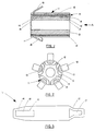
- the barrel commutator shown in Figures 1 and 2 comprises a base 10 and a plurality of commutator segments 11 secured to the base 10 in equi-angularly spaced relationship.
- the base 10 comprises an electrically insulating pre-formed tubular base part 12, typically of plastics material, and a sleeve 13 of moulded material within the base part 12 securing the segments 11 firmly to the base part 12.
- Each segment 11 has hook-shaped lugs 14 and 15 at opposite ends to locate the segments 11 on the base part 12.
- the base part 12 has castellated ends and apertures 16 and 17 in the lugs 14 and 15, respectively, engage with the castellations to locate the segments 11 angularly with respect to the base part 12.
- Each segment 11 has an integral tang 18 at one end.
- the tang 18 is cut out from the lug 14 leaving the aperture 16 and is used to connect a wire of a wound armature to the segment 11.
- the inner surface of the base part 12 is uneven to create cavities between the lugs 14 and 15 and the base part 12 so that the moulded material forming the sleeve 13 gets into these cavities to better clamp the segments 11 to the base part 12.
- longitudinally extending ribs 19 are provided on the inside of the base part 12. These ribs 19 extend beyond the free ends of the hook-shaped lugs 14 and 15 but not to the ends of the base part 12 and support the lugs 14 and 15 away from the inside surface of the base part 12 to create the aforesaid cavities.
- the commutator is made as follows: Each segment 11 is blanked out (see Figure 3) and formed into its final shape shown in Figures 1 and 2 with the exception of the lug 15. The segments 11 are then mounted on the pre-formed base part 12 by sliding them along the base part 12 from the left hand end thereof as viewed in Figure 1 until the apertures 16 in radial limbs of the lugs 14 engage with the castellations at the left hand end of the base part 12 and the free ends of the longitudinally extending limbs of the lugs 14 contact respective ribs 19.
- the lugs 15 are then bent over the right hand end of the base part 12 so that the apertures 17 in the radial limbs of the lugs 15 engage with the castellations at the right hand end of the base part 12 and the free ends of the longitudinally extending limbs of the lugs 15 contact respective ribs 19.
- the base part 12 together with the commutator segments 11 is then placed in a mould.
- Thermoplastics material or injection grade thermosetting plastics material is then introduced into the inside of the base part 12 filling all cavities between the lugs 14 and 15 and the inner surface of the base part 12 and forming the sleeve 13.
- This moulded sleeve 13 firmly locks the segments 11 to the base part 12 allowing the segments 11 to be machined without risk of displacing the segments 11 with respect to the base part 12.
- the finished commutators can then be mounted fast on an armature shaft of an electric motor, typically a small fractional horsepower p.m.d.c. motor, and the armature winding is welded or otherwise secured to the tangs 18.
- an electric motor typically a small fractional horsepower p.m.d.c. motor
Landscapes
- Motor Or Generator Current Collectors (AREA)
- Switch Cases, Indication, And Locking (AREA)
Description
- This invention relates to a commutator, to an electric motor equipped with such a commutator, and to a method of manufacturing a commutator.
- Commutators for small fractional horsepower motors are most commonly made by insert moulding. In barrel commutators, the commutator segments are commonly formed as an integral sleeve and the commutator base is moulded to this sleeve. Slits are subsequently made through the sleeve to form the individual commutator segments. A moulded commutator can also be formed such as disclosed in Patents Abstract of Japan, volume 9, no.208 (E-338) 1931, 24th August 1985 JP-A-6070950. The manufacturing processes are complicated and in recent years some manufacturers have been turning to assembled commutators in which individual segments are mechanically secured to a pre-formed base such as described in USA 1410914. It is, however, desirable to machine these commutators to perfect roundness after assembly and it has proven difficult to mechanically secure the segments to a pre-formed base in a manner which prevents circumferential displacement of the segments during a machining operation.
- According to the present invention there is provided a commutator comprising a plurality of commutator segments mounted on a pre-formed tubular electrically insulating commutator base part in equi-angularly spaced relationship, each segment having a hook-shaped lug at each of two opposite ends, the hook-shaped lugs extending inside opposite ends of the pre-formed base part and the commutator segments being firmly secured to the pre-formed base part by plastics material moulded to the pre-formed base part and the lugs of the commutator segments after the segments have been mounted on the base part.
- The segments are thus firmly secured to the base part so that machining, and if necessary welding, can be carried out without displacing the segments relative to the base part.
- Preferably, each lug also engages with a respective end of the pre-formed base part so as to locate the lug angularly with respect to the base part. This may be achieved, for example, by providing the ends of the base part with castellations and engaging the lugs with the castellations.
- Advantageously, the moulded plastics material forms a sleeve within the pre-formed base part so that this sleeve can be mounted fast on a shaft.
- The invention will now be more particularly described by way of example with reference to the accompanying drawings, wherein
- Figure 1 is a longitudinal section through one embodiment of a commutator according to the invention,
- Figure 2 is an end view taken in the direction of arrow A of Figure 1, and
- Figure 3 is a plan view of one of the commutator segments shown partially formed.
- Referring to the drawings, the barrel commutator shown in Figures 1 and 2 comprises a
base 10 and a plurality ofcommutator segments 11 secured to thebase 10 in equi-angularly spaced relationship. Thebase 10 comprises an electrically insulating pre-formedtubular base part 12, typically of plastics material, and asleeve 13 of moulded material within thebase part 12 securing thesegments 11 firmly to thebase part 12. - Each
segment 11 has hook-shaped lugs segments 11 on thebase part 12. Thebase part 12 has castellated ends andapertures lugs segments 11 angularly with respect to thebase part 12. - Each
segment 11 has anintegral tang 18 at one end. Thetang 18 is cut out from thelug 14 leaving theaperture 16 and is used to connect a wire of a wound armature to thesegment 11. - The inner surface of the
base part 12 is uneven to create cavities between thelugs base part 12 so that the moulded material forming thesleeve 13 gets into these cavities to better clamp thesegments 11 to thebase part 12. In the embodiment shown, longitudinally extendingribs 19 are provided on the inside of thebase part 12. Theseribs 19 extend beyond the free ends of the hook-shaped lugs base part 12 and support thelugs base part 12 to create the aforesaid cavities. - The commutator is made as follows:
Eachsegment 11 is blanked out (see Figure 3) and formed into its final shape shown in Figures 1 and 2 with the exception of thelug 15. Thesegments 11 are then mounted on thepre-formed base part 12 by sliding them along thebase part 12 from the left hand end thereof as viewed in Figure 1 until theapertures 16 in radial limbs of thelugs 14 engage with the castellations at the left hand end of thebase part 12 and the free ends of the longitudinally extending limbs of thelugs 14 contactrespective ribs 19. Thelugs 15 are then bent over the right hand end of thebase part 12 so that theapertures 17 in the radial limbs of thelugs 15 engage with the castellations at the right hand end of thebase part 12 and the free ends of the longitudinally extending limbs of thelugs 15 contactrespective ribs 19. - The
base part 12 together with thecommutator segments 11 is then placed in a mould. Thermoplastics material or injection grade thermosetting plastics material is then introduced into the inside of thebase part 12 filling all cavities between thelugs base part 12 and forming thesleeve 13. Thismoulded sleeve 13 firmly locks thesegments 11 to thebase part 12 allowing thesegments 11 to be machined without risk of displacing thesegments 11 with respect to thebase part 12. - The finished commutators can then be mounted fast on an armature shaft of an electric motor, typically a small fractional horsepower p.m.d.c. motor, and the armature winding is welded or otherwise secured to the
tangs 18.
Claims (7)
- A commutator comprising a plurality of commutator segments (11) mounted on a pre-formed tubular electrically insulating commutator base part (12) in equi-angularly spaced relationship, each segment having a hook-shaped lug (14, 15) at each of two opposite ends, the hook-shaped lugs extending inside opposite ends of the pre-formed base part (12), characterised in that the commutator segments (11) are firmly secured to the pre-formed base part (12) by plastics material (13) moulded to the pre-formed base part (12) and the lugs (14, 15) of the commutator segments (11) after the segments have been mounted on the base part (12).
- A commutator as claimed in claim 1, characterised in that an end of the pre-formed base part (12) is castellated and the lugs (15) engage over the castellations.
- A commutator as claimed in claim 1 or claim 2, characterised in that the moulded plastics material forms a sleeve (13) within the pre-formed base part (12).
- A commutator as claimed in any one of claims 1 to 3, characterised in that the inner surface of the pre-formed base part is uneven to create cavities between the lugs (14, 15) and the pre-formed base part (12), which cavities are filled with the moulded plastics material.
- A commutator as claimed in any one of the preceding claims, characterised in that each segment (12) has an integral tang (18) for connection to a wire of a wound armature.
- A fractional horsepower electric motor equipped with a commutator according to any one of the preceding claims.
- A method of manufacturing the commutator of any one of claims 1 to 5, characterised by placing the commutator segments (11) on the pre-formed base part (12) with their hook-shaped lugs (14, 15) extending inside opposite ends of the base part (12), and moulding plastics material (13) to the pre-formed base part and the commutator segments (12) to firmly secure the commutator segments (11) and lugs (14, 15) to the pre-formed base part (12).
Applications Claiming Priority (2)
| Application Number | Priority Date | Filing Date | Title |
|---|---|---|---|
| GB8801093A GB2214723B (en) | 1988-01-19 | 1988-01-19 | A commutator |
| GB8801093 | 1988-02-15 |
Publications (3)
| Publication Number | Publication Date |
|---|---|
| EP0325353A2 EP0325353A2 (en) | 1989-07-26 |
| EP0325353A3 EP0325353A3 (en) | 1989-12-06 |
| EP0325353B1 true EP0325353B1 (en) | 1994-04-13 |
Family
ID=10630169
Family Applications (1)
| Application Number | Title | Priority Date | Filing Date |
|---|---|---|---|
| EP89300184A Expired - Lifetime EP0325353B1 (en) | 1988-01-19 | 1989-01-10 | A commutator |
Country Status (9)
| Country | Link |
|---|---|
| US (1) | US5128578A (en) |
| EP (1) | EP0325353B1 (en) |
| JP (1) | JPH01286753A (en) |
| CN (1) | CN1028269C (en) |
| BR (1) | BR8900206A (en) |
| DE (1) | DE68914476T2 (en) |
| ES (1) | ES2055025T3 (en) |
| GB (1) | GB2214723B (en) |
| HK (1) | HK131394A (en) |
Families Citing this family (9)
| Publication number | Priority date | Publication date | Assignee | Title |
|---|---|---|---|---|
| CH681673B5 (en) * | 1990-12-14 | 1993-11-15 | Rolex Montres | display wristwatch conceals. |
| DE69205257T2 (en) * | 1991-11-12 | 1996-04-11 | Johnson Electric Sa | Assembled commutator. |
| GB9516329D0 (en) * | 1995-08-09 | 1995-10-11 | Johnson Electric Sa | Commutator |
| DE19642138A1 (en) * | 1996-10-12 | 1998-04-23 | Kirkwood Ind Gmbh | Method of manufacturing commutators and commutator manufactured by the method |
| US5955812A (en) * | 1997-06-09 | 1999-09-21 | Joyal Products Co., Inc. | Electric motor with carbon track commutator |
| US7009323B1 (en) | 2004-12-06 | 2006-03-07 | Siemens Vdo Automotive Inc. | Robust commutator bar anchoring configuration with dove-tailed features |
| CN102931557B (en) * | 2011-08-09 | 2016-11-16 | 德昌电机(深圳)有限公司 | Commutator and its preparation method |
| CN104332793A (en) * | 2014-07-31 | 2015-02-04 | 瑞安市恒丰机电有限公司 | Commutator |
| CN105889619B (en) * | 2014-12-05 | 2018-11-27 | 江苏亚力亚气动液压成套设备有限公司 | A kind of mechanical trip commutator sealing copper ring |
Family Cites Families (7)
| Publication number | Priority date | Publication date | Assignee | Title |
|---|---|---|---|---|
| US1410914A (en) * | 1917-10-23 | 1922-03-28 | Forest H Hartzell | Commutator for electric motors |
| FR1451412A (en) * | 1965-07-08 | 1966-01-07 | Advanced training in rotating electrical appliance collectors | |
| GB1130123A (en) * | 1967-01-11 | 1968-10-09 | Ver Volkseigener Betr E Elektr | Commutator for electric machines |
| CH552288A (en) * | 1972-10-17 | 1974-07-31 | Bbc Brown Boveri & Cie | METHOD OF MANUFACTURING A COLLECTOR FOR ROTATING ELECTRIC MACHINERY. |
| FR2437709A1 (en) * | 1978-09-27 | 1980-04-25 | Paris & Du Rhone | FRONT COLLECTOR FOR ROTATING ELECTRIC MACHINE |
| US4559464A (en) * | 1983-06-27 | 1985-12-17 | General Electric Company | Molded commutator and method of manufacture |
| DD231684A1 (en) * | 1984-12-21 | 1986-01-02 | Prefo Werk 4 Kleinstmotoren Ve | COMMUTATOR FOR SMALL MACHINES |
-
1988
- 1988-01-19 GB GB8801093A patent/GB2214723B/en not_active Expired - Fee Related
-
1989
- 1989-01-10 DE DE68914476T patent/DE68914476T2/en not_active Expired - Fee Related
- 1989-01-10 ES ES89300184T patent/ES2055025T3/en not_active Expired - Lifetime
- 1989-01-10 EP EP89300184A patent/EP0325353B1/en not_active Expired - Lifetime
- 1989-01-18 US US07/298,351 patent/US5128578A/en not_active Expired - Fee Related
- 1989-01-18 BR BR898900206A patent/BR8900206A/en unknown
- 1989-01-19 JP JP1010944A patent/JPH01286753A/en active Pending
- 1989-01-19 CN CN89100334A patent/CN1028269C/en not_active Expired - Fee Related
-
1994
- 1994-11-24 HK HK131394A patent/HK131394A/en not_active IP Right Cessation
Non-Patent Citations (2)
| Title |
|---|
| PATENT ABSTRACTS OF JAPAN, vol. 8, no. 161 (E-257)(1598), 26 July 1984 & JP-A-59-61451 * |
| PATENT ABSTRACTS OF JAPAN, vol. 9, no. 208 (E-338)(1931), 24 August 1985 & JP-A-60-70950. * |
Also Published As
| Publication number | Publication date |
|---|---|
| HK131394A (en) | 1994-12-02 |
| GB2214723A (en) | 1989-09-06 |
| DE68914476T2 (en) | 1994-08-04 |
| US5128578A (en) | 1992-07-07 |
| DE68914476D1 (en) | 1994-05-19 |
| GB2214723B (en) | 1992-01-29 |
| BR8900206A (en) | 1989-09-12 |
| GB8801093D0 (en) | 1988-02-17 |
| JPH01286753A (en) | 1989-11-17 |
| EP0325353A2 (en) | 1989-07-26 |
| EP0325353A3 (en) | 1989-12-06 |
| CN1036107A (en) | 1989-10-04 |
| ES2055025T3 (en) | 1994-08-16 |
| CN1028269C (en) | 1995-04-19 |
Similar Documents
| Publication | Publication Date | Title |
|---|---|---|
| US5727307A (en) | Method for manufacturing an armature for an electric motor | |
| EP0667657B1 (en) | Method of manufacturing a planar carbon segment commutator. | |
| US5486732A (en) | Slip ring unit for fitting to an alternator, especially for a motor vehicle | |
| US4263711A (en) | Method of making armature of double insulation construction | |
| US5530311A (en) | Face type commutator with sideways tangs and a method of making the commutator | |
| US4064410A (en) | Squirrel cage rotor and method of making same | |
| US4857787A (en) | Armature of a.c. generator for a car and method of manufacturing the same | |
| US8220146B2 (en) | Method of manufacturing short-circuiting member | |
| US6057626A (en) | Commutator for a dynamo-electric machine and method of manufacture therefor | |
| US3861026A (en) | Method of making dynamoelectric machines | |
| US3829720A (en) | Motor stator | |
| US5521450A (en) | Slip ring unit for fitting to an alternator, especially for a motor vehicle | |
| US5459364A (en) | Slip ring unit for fitting to an alternator, especially for a motor vehicle | |
| US5124609A (en) | Commutator and method of manufacturing the same | |
| EP0325353A2 (en) | A commutator | |
| US5432993A (en) | Method of making a cylindrical carbon segment commutator | |
| US3450914A (en) | Commutators of rotary electric machines | |
| US4638202A (en) | Commutator and method of making same | |
| EP1314235B1 (en) | Planar commutator segement attachment method and assembly | |
| US8115363B2 (en) | Commutator | |
| JP4056261B2 (en) | Planar carbon segment commutator | |
| US4408140A (en) | Commutator assembly with hook members | |
| US5107160A (en) | Electrical commutator with reinforced connectors | |
| US4890377A (en) | Method of making cummutators | |
| KR20070084528A (en) | Commutator's manufacturing method and commutator |
Legal Events
| Date | Code | Title | Description |
|---|---|---|---|
| PUAI | Public reference made under article 153(3) epc to a published international application that has entered the european phase |
Free format text: ORIGINAL CODE: 0009012 |
|
| AK | Designated contracting states |
Kind code of ref document: A2 Designated state(s): DE ES FR GB IT |
|
| PUAL | Search report despatched |
Free format text: ORIGINAL CODE: 0009013 |
|
| AK | Designated contracting states |
Kind code of ref document: A3 Designated state(s): DE ES FR GB IT |
|
| 17P | Request for examination filed |
Effective date: 19900410 |
|
| 17Q | First examination report despatched |
Effective date: 19920525 |
|
| GRAA | (expected) grant |
Free format text: ORIGINAL CODE: 0009210 |
|
| AK | Designated contracting states |
Kind code of ref document: B1 Designated state(s): DE ES FR GB IT |
|
| ITF | It: translation for a ep patent filed | ||
| REF | Corresponds to: |
Ref document number: 68914476 Country of ref document: DE Date of ref document: 19940519 |
|
| ET | Fr: translation filed | ||
| REG | Reference to a national code |
Ref country code: ES Ref legal event code: FG2A Ref document number: 2055025 Country of ref document: ES Kind code of ref document: T3 |
|
| PLBE | No opposition filed within time limit |
Free format text: ORIGINAL CODE: 0009261 |
|
| STAA | Information on the status of an ep patent application or granted ep patent |
Free format text: STATUS: NO OPPOSITION FILED WITHIN TIME LIMIT |
|
| 26N | No opposition filed | ||
| PGFP | Annual fee paid to national office [announced via postgrant information from national office to epo] |
Ref country code: GB Payment date: 19970102 Year of fee payment: 9 |
|
| PGFP | Annual fee paid to national office [announced via postgrant information from national office to epo] |
Ref country code: FR Payment date: 19970109 Year of fee payment: 9 |
|
| PGFP | Annual fee paid to national office [announced via postgrant information from national office to epo] |
Ref country code: DE Payment date: 19970120 Year of fee payment: 9 |
|
| PGFP | Annual fee paid to national office [announced via postgrant information from national office to epo] |
Ref country code: ES Payment date: 19970124 Year of fee payment: 9 |
|
| PG25 | Lapsed in a contracting state [announced via postgrant information from national office to epo] |
Ref country code: GB Free format text: LAPSE BECAUSE OF NON-PAYMENT OF DUE FEES Effective date: 19980110 |
|
| PG25 | Lapsed in a contracting state [announced via postgrant information from national office to epo] |
Ref country code: ES Free format text: LAPSE BECAUSE OF NON-PAYMENT OF DUE FEES Effective date: 19980112 |
|
| PG25 | Lapsed in a contracting state [announced via postgrant information from national office to epo] |
Ref country code: FR Free format text: THE PATENT HAS BEEN ANNULLED BY A DECISION OF A NATIONAL AUTHORITY Effective date: 19980131 |
|
| GBPC | Gb: european patent ceased through non-payment of renewal fee |
Effective date: 19980110 |
|
| PG25 | Lapsed in a contracting state [announced via postgrant information from national office to epo] |
Ref country code: DE Free format text: LAPSE BECAUSE OF NON-PAYMENT OF DUE FEES Effective date: 19981001 |
|
| REG | Reference to a national code |
Ref country code: FR Ref legal event code: ST |
|
| REG | Reference to a national code |
Ref country code: ES Ref legal event code: FD2A Effective date: 20000403 |
|
| PG25 | Lapsed in a contracting state [announced via postgrant information from national office to epo] |
Ref country code: IT Free format text: LAPSE BECAUSE OF NON-PAYMENT OF DUE FEES Effective date: 20050110 |