EP0326569B1 - Magasin pour objets en forme de feuille - Google Patents
Magasin pour objets en forme de feuille Download PDFInfo
- Publication number
- EP0326569B1 EP0326569B1 EP87906589A EP87906589A EP0326569B1 EP 0326569 B1 EP0326569 B1 EP 0326569B1 EP 87906589 A EP87906589 A EP 87906589A EP 87906589 A EP87906589 A EP 87906589A EP 0326569 B1 EP0326569 B1 EP 0326569B1
- Authority
- EP
- European Patent Office
- Prior art keywords
- cassette
- store
- locking device
- locking
- sheet
- Prior art date
- Legal status (The legal status is an assumption and is not a legal conclusion. Google has not performed a legal analysis and makes no representation as to the accuracy of the status listed.)
- Expired - Lifetime
Links
- 238000004891 communication Methods 0.000 claims abstract description 3
- 238000003780 insertion Methods 0.000 claims description 15
- 230000037431 insertion Effects 0.000 claims description 15
- 230000005291 magnetic effect Effects 0.000 claims description 14
- XEEYBQQBJWHFJM-UHFFFAOYSA-N Iron Chemical group [Fe] XEEYBQQBJWHFJM-UHFFFAOYSA-N 0.000 claims description 5
- 230000004044 response Effects 0.000 claims description 4
- 239000003302 ferromagnetic material Substances 0.000 claims description 3
- 230000003993 interaction Effects 0.000 claims description 2
- 239000000523 sample Substances 0.000 description 37
- 238000000465 moulding Methods 0.000 description 15
- 229920003023 plastic Polymers 0.000 description 9
- 239000004033 plastic Substances 0.000 description 9
- 230000006835 compression Effects 0.000 description 6
- 238000007906 compression Methods 0.000 description 6
- 230000007246 mechanism Effects 0.000 description 3
- RYGMFSIKBFXOCR-UHFFFAOYSA-N Copper Chemical compound [Cu] RYGMFSIKBFXOCR-UHFFFAOYSA-N 0.000 description 2
- 230000000712 assembly Effects 0.000 description 2
- 238000000429 assembly Methods 0.000 description 2
- 230000002301 combined effect Effects 0.000 description 2
- UFULAYFCSOUIOV-UHFFFAOYSA-N cysteamine Chemical compound NCCS UFULAYFCSOUIOV-UHFFFAOYSA-N 0.000 description 2
- 230000004907 flux Effects 0.000 description 2
- CWYNVVGOOAEACU-UHFFFAOYSA-N Fe2+ Chemical compound [Fe+2] CWYNVVGOOAEACU-UHFFFAOYSA-N 0.000 description 1
- 230000009471 action Effects 0.000 description 1
- 230000008901 benefit Effects 0.000 description 1
- 229910052802 copper Inorganic materials 0.000 description 1
- 239000010949 copper Substances 0.000 description 1
- 230000008878 coupling Effects 0.000 description 1
- 238000010168 coupling process Methods 0.000 description 1
- 238000005859 coupling reaction Methods 0.000 description 1
- 230000005284 excitation Effects 0.000 description 1
- 239000000696 magnetic material Substances 0.000 description 1
- 239000000463 material Substances 0.000 description 1
- 238000012856 packing Methods 0.000 description 1
- 230000002265 prevention Effects 0.000 description 1
- 230000035939 shock Effects 0.000 description 1
- 238000011179 visual inspection Methods 0.000 description 1
Images


Classifications
-
- B—PERFORMING OPERATIONS; TRANSPORTING
- B65—CONVEYING; PACKING; STORING; HANDLING THIN OR FILAMENTARY MATERIAL
- B65H—HANDLING THIN OR FILAMENTARY MATERIAL, e.g. SHEETS, WEBS, CABLES
- B65H31/00—Pile receivers
- B65H31/04—Pile receivers with movable end support arranged to recede as pile accumulates
- B65H31/12—Devices relieving the weight of the pile or permitting or effecting movement of the pile end support during piling
- B65H31/14—Springs
-
- B—PERFORMING OPERATIONS; TRANSPORTING
- B65—CONVEYING; PACKING; STORING; HANDLING THIN OR FILAMENTARY MATERIAL
- B65H—HANDLING THIN OR FILAMENTARY MATERIAL, e.g. SHEETS, WEBS, CABLES
- B65H1/00—Supports or magazines for piles from which articles are to be separated
- B65H1/08—Supports or magazines for piles from which articles are to be separated with means for advancing the articles to present the articles to the separating device
- B65H1/12—Supports or magazines for piles from which articles are to be separated with means for advancing the articles to present the articles to the separating device comprising spring
-
- G—PHYSICS
- G07—CHECKING-DEVICES
- G07D—HANDLING OF COINS OR VALUABLE PAPERS, e.g. TESTING, SORTING BY DENOMINATIONS, COUNTING, DISPENSING, CHANGING OR DEPOSITING
- G07D11/00—Devices accepting coins; Devices accepting, dispensing, sorting or counting valuable papers
- G07D11/10—Mechanical details
- G07D11/12—Containers for valuable papers
- G07D11/125—Secure containers
Definitions
- the invention relates to a sheet store comprising a container having an access opening; a closure member for closing the access opening; and a locking device for locking the closure member in its closed position.
- Such stores are hereinafter referred to as of the kind described.
- Typical locking devices include key operated locks with the number of keys available for operating the lock being limited to prevent fraudulent access.
- simple key operated locks of this type are not impossible to overcome by a skilled lock picker or by someone who gains unauthorised access to the key.
- GB-A-1268362 describes a bolt housing, keeper and magnetised bolt which can be released using an external magnet to move the bolt.
- EP-A-0004436 describes a banknote cassette for insertion into a housing which causes the unloading doors to be unlocked on insertion of the housing.
- a sheet store comprises a container having an access opening; a closure member for closing the access opening; and a first locking device for locking the closure member in its closed position wherein the first locking device is actuated to unlock said closure member by contact less communication through a wall of said container, the first locking device comprising an electrically conductive member which is movable between locked and unlocked positions, the member being biassed towards one of the positions and movable to the other position in response to the generation of a magnetic field in the vicinity of the member, characterised in that the electrically conductive member is made of non-ferromagnetic material whereby when the lock member is brought into the vicinity of an AC magnetic field, eddy currents are generated in the member which then moves against the bias due to the interaction of the AC magnetic field and the field generated by the eddy currents.
- This invention has the significant advantage that the location of the locking member and the manner in which it is operated cannot be determined from a visual inspection of the store. Furthermore, in a preferred example in which the store further comprises a second, key operated lock for locking the closure member in the closed position, an unauthorised user would not even suspect the presence of the first locking device.
- the electrically conductive member may comprise an electrically conductive ring of non-ferromagnetic material mounted on a soft iron core within the sheet store container.
- the locking device may comprise a core member around which is wound a coil electrically connected to a solenoid having a plunger, whereby when a changing magnetic flux is coupled into the core, a current flows in the coil to move the plunger away from a closure member locking position.
- sheet handling apparatus comprises a sheet store housing and a sheet store in accordance with the first aspect of the present invention, the sheet store housing including actuating means for actuating an AC magnetic field to cause operation of the locking device upon insertion of the store into the store housing.
- the actuating means may comprise magnetic field generating means such as a solenoid.
- the closure member comprises a slidable shutter, control means for moving the closure member between its open and closed positions, the first locking device cooperating with the control means to prevent or permit the control means to operate in accordance with the first locking device being in its locked or unlocked position respectively.
- control means may comprise a co-operating rack and pinion, the rack being coupled to the closure device, and the pinion co-operating with the first locking device, the first locking device preventing rotation of the pinion in its locked position.
- Figure 1 illustrates a banknote cassette 10 which can be used in either a cash accepting mode or a cash dispensing mode. Figure 1 also illustrates parts of cash dispensing apparatus.
- the cassette 10 comprises an outer casing 11 having a lid 12 hinged to the casing 11 at 13.
- the lid 12 is arranged to be swung open by means of a slot 170 in the cassette housing of a cash dispenser along which slides a cam 14 fixed to the lid 12.
- the slot 170 extends at an angle to the direction of insertion of the cassette 10 into the housing.
- the lid 12 is cut away at its leading end to form an aperture 15 of rectangular form.
- the aperture 15 is closed by an upper shutter 16 made of tough plastics material which is slidably mounted to the lid.
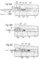
- the shutter 16 is shown in more detail in Figure 2A.
- the upper shutter 16 comprises a planar section 16A having a pair of laterally extending abutments 23 at its forward end and a pair of laterally extending wings 20 at its rearward end, each wing 20 having an aperture which receives one end of a respective tension spring 18.
- the forward end of the shutter 16 has a depending skirt 16B.
- the upper shutter 16 is slidably mounted between a pair of L-shaped rails 17A, 17B, the rail 17A being shown in more detail in Figure 2B.
- the rails 17A, 17B are mounted to the underside of the lid 12 via respective flanges 17C.
- Each rail 17A, 17B has a lower flange section 17D on which is fixed an upwardly extending pin 19.
- each rail 17A, 17B has an aperture 22 positioned forwardly of the pin 19.
- the upper shutter 16 rests on the laterally extending portions 17D of the rails with the free ends of the tension springs 18 connected to respective pins 19 as shown in Figure 2A.
- the upper shutter 16 is urged in the forward direction to the closed position shown in Figure 1 by the springs 18.
- the skirt 16B of the upper shutter abuts against the front flange portions 12A, 12B of the lid 12.
- the upper shutter 16 is prevented from moving in a rearward direction by a pair of stop members 21 which, in a locked position, protrude through the apertures 22 in the rails 17A, 17B and abut against the adjacent abutments 23.
- the operation of the stop members 21 will be explained in more detail below.
- a pair of control assemblies 30,31 are provided on opposite side walls 12, 11 of the cassette.
- the control assembly 31 constitutes a tamper-proof assembly and is shown in more detail in Figures 4A-4C.
- This assembly comprises a plastics moulding 31A having a slide member 32 which is moved to and fro within a slot 32A by a lever shown diagram- matically at 33.
- the position of the lever 33 is controlled by a key operated lock 34 ( Figure 1), details of the lock being omitted from Figure 4A, for clarity.
- the cassette In the position shown in Figure 4A, the cassette is in the locked condition with a red indicator 35 being visible through a window 36 in the side wall 11. Clockwise movement of the key (as viewed in Figure 1) will move the lever 33 so that the slide member 32 will move to the left, as seen in Figure 4A, against the force of a compression spring 37 connected between one end of a slot 37A in the slide member 32 and part of the plastics moulding 31A.
- a locking member 39 is slidably mounted in a vertical slot 40 of the moulding 31A and is urged in a downward direction by a compression spring 42 provided in the slot 40.
- the locking member 39 carries laterally extending pin 38 which is positioned within an aperture 32B of the slide member 32.
- the lower, inner surface of the aperture 32B includes a ramp section 41 and a notch 43.
- control assembly also includes a rack and pinion assembly comprising a rack 63 ( Figures 4B, 4C) and a pinion 64 ( Figure 1) with tooted segments mounted on a spindle 65.
- the teeth of the pinion 64 engage the teeth of the rack 63.
- the rack 63 also includes an upstanding flange section 65 having at its leading end a cam surface 63A.
- the lower end of the locking member 39 engages the upper surface of the flange 65, the rack 63 being slidable along a groove 66 of the moulding 31A.
- the rack 63 is locked to the moulding 31A in a manner (not shown) similar to the manner in which a rack 70 is locked to a moulding 48, described below.
- the operation of the tamper-proof assembly 31 is as follows.
- a probe 67 fixed to the housing enters into a slot 68 in the leading end of the cassette.
- This slot communicates with the slot 66 so that the probe 67 locks with and pushes the rack 63 in a rearward direction, as seen in Figure 1.
- the locking of the probe 67 to the rack 63 is similar to the locking of a probe 73 to the rack 70.
- the tamper-proof assembly will have been primed with the pin 38 located in the notch 43, as seen in Figure 4B.
- this tamper-proof assembly 31 is to allow the cassette only to be opened by a key holder. Any attempt to tamper with the cassette in its primed condition, will cause the locking mechanism to trip to the position shown in Figure 4A so that the red indicator 35 is visible through the window 36 signifying that tampering has taken place. It is impossible to reset the "red" indication without a key.
- control assembly 31 Prevention of the cassette from being opened is achieved indirectly by the control assembly 31 since by preventing the probe 67 from moving the rack 63 along the slot 66 a similar operation is prevented from occurring in the control assembly 30 to be described below. It is the control assembly 30 which controls opening and closing of the cassette.
- the lid 12 itself can be opened, primarily when the cassette is used in a cash dispenser. Normally, however, the lid 12 is locked in the closed position by a locking mechanism comprising a pin 25 ( Figures 2B and 3) extending from the side wall 11 to a flange 26 attached to the lower section 17D of the rail 17A. The lid is locked in its closed position by the engagement of a hook portion 55 of a rotatably mounted toothed segment of pinion 45 of the control assembly 30. This is shown in more detail in Figure 5.
- the control assembly 30 shown in Figures 5 - 8 controls the opening and closing of the upper shutter 16, the opening and closing of a front shutter 29, the locking of the lid 12 (as explained above) and the bias applied to a packer plate within the cassette (as explained in more detail below).
- the control assembly 30 has a toothed segment 45 which is pivotally mounted to a plastics moulding 48 by a pin 46.
- the pin 46 is set into a boss 47 of the moulding 48, as seen in Figure 7.
- a rack 70 is slidably mounted in a slot 71 of the moulding 48 and engages the teeth of a portion 72 of the segment 45. Movement of the rack 70 is controlled by a probe 73 mounted in the housing of the cash dispenser or cash acceptor into which the cassette is inserted, the probe 73 passing through an aperture 74 in the front end 27 of the cassette, the aperture 74 communicating with the slot 71.
- the rack 70 has a blind bore 180 and an aperture 181 passing through a wall of the bore 180.
- the rack 70 is locked in the position shown in Figure 14A by a disc 182 which is received in a recess 183 of the slot 71 and protrudes into the aperture 181 of the rack 70.
- the disc 182 is prevented from passing through the aperture 181 by a plunger 184 slidably mounted in the bore 180 and biassed towards the position shown in Figure 14A by a compression spring 185.
- the rack 70 is prevented from moving to the left in Figure 14A by part of the front wall 27 of the container 11.
- the probe 73 When the probe 73 enters the aperture 74 in the container 11 aligned with the rack 70, it enters into the bore 180 of the rack 70 and pushes the plunger 184 further into the bore against the spring action. This movement brings an aperture 186 in the probe 73 into alignment with the aperture 181 in the rack 70 as shown in Figure 14B. Further movement of the cassette relative to the probe 73 causes the probe to push the rack 70 along the slot 71. This movement of the rack 70 acts on the disc 182 which cooperates with a cam face 187 on the moulding 48 and the wall of the aperture 181 to move into the apertures 181, 186 thus locking the probe and the rack together. Thereafter, as shown in Figure 14C, the probe 10 can push the rack 70 (either directly or via movement of the cassette relative to the probe) or can pull it via the disc 182.
- the front 27 of the cassette 10 is cut away to form an aperture 28 which is closed by a front shutter 29, the upper end 24 of the shutter 29 being located, in its closed position, under the skirt 16B of the upper shutter 16.
- Opposite sides of the shutter 29 are provided with respective racks 75 (one of which is shown in Figure 5) which engage a toothed section 76 of the segment 45, and the pinion 64. It will be seen therefore that movement of the rack 70 within the slot 71 will cause the front shutter 29 to be driven downwardly, upon insertion of the probe 73, and upwardly upon withdrawal of the probe 73 due to the corresponding rotation of the segment 45.
- the stop member 21 controlled by the assembly 30 is integrally formed with a slide member 57 ( Figures 7 and 9), this unit being slidable within a slot 58 of the plastics moulding 48.
- the slide member 57 carries a pin 56 which is received in an aperture 77 formed in the segment 45.
- the other stop member 21 is controlled in a similar manner by the pinion 64 of the control assembly.
- the control assembly 30 is also provided with an auxiliary locking device to further prevent fraudulent operation of the control assembly by, for example, pushing a probe into the aperture 74 with the tamper-proof mechanism either reset or locked.
- This additional locking facility is provided by a contactless lock including a repulsion ring member 50 made of a conductive non-ferrous, non-magnetic material (such as copper) mounted on a soft iron core pin 51 set into the plastics moulding 48.
- a surface 49 of the segment 45 engages the ring member 50 thus preventing clockwise rotation of the segment and hence downward, opening motion of the shutter 29.
- the ring 50 is urged towards its locked position shown in Figures 5 and 8 by a compression spring 52.
- an AC coil and soft iron core combination 78 mounted behind a wall 171 ( Figure 1) of the cassette housing of the cash dispenser or cash acceptor into which the cassette is to be inserted, is an AC coil and soft iron core combination 78 positioned such that upon insertion of the cassette into the housing, the coil and core combination 78 when energised will repulse the ring member 50 away from it (due to eddy current affects), thus moving the ring member out of engagement with the surface 49. This then permits clockwise rotation of the segment 45 ( Figure 6).
- the AC coil and iron core combination 78 is de-energised or the ring member moves out of the influence of the magnetic field produced by the combination 78, the ring member 50 tries to return to the position shown in Figure 5 under the influence of spring 52.
- a balance member 53 is provided, pivoted to the plastics moulding 48 about an axis 54.
- the member 53 is arranged to balance the dead weight of the copper ring 50.
- FIG. 10 An alternative form of a contactless lock is shown in Figure 10 in which one half of a transformer 86 is provided in the cassette housing and comprises a U-shaped core 87 around which is provided a coil 88 connected to an AC source 89.
- the other half of the transformer is mounted within the plastics moulding 48 in place of the ring member 50 and core 51 and comprises a corresponding U-shaped core 90 around which is wound a coil 91 coupled to a solenoid 92.
- a plunger member 93 of the solenoid is urged in an axially outward direction from the solenoid by a compression spring (not shown) and is retracted from this locking position upon energisation of the solenoid 92.
- Such energisation will occur during insertion of the cassette into the cassette housing in the direction of the arrow 94 when sufficient flux couples from the core 87 into the core 90.
- the cassette 10 has an inner floor 110, the underside of which is shown in Figure 11.
- the floor 110 comprises a flat plate 111 with depending sides 112, 113.
- a slot 114 extends almost the whole length of the plate 111 and a carrier guide 115 is slidably mounted in the slot 114 for movement from the front of the cassette (full line position) to the back of the cassette (dotted line position).
- the carrier guide 115 carries a packer plate 150 ( Figure 1) on the upper surface of the floor 110, the packer plate 150 urging the stack of banknotes within the cassette towards the front of the cassette.
- This urging of the packer plate 150 is achieved via the carrier guide 115 which is coupled to a pair of tension springs 151, 152.
- Spring 152 is made of relatively light gauge wire while spring 151 is made of relatively heavy gauge wire.
- the spring 151 extends around a guide 116 and is connected to a light gauge spring 153 by a spring connector 124.
- the light spring 153 is anchored at its end opposite from the connector 124 to the floor 110.
- the spring connector 124 is a cylindrical sleeve into which the looped ends of the springs 151, 153 are placed with a pin then being passed through the overlapping loops forming a rigid connection between the end of both springs and the cylinder.
- the pin passes through a hole drilled at right angles to the axis of the cylinder and lies flush with the outside wall being a tight fit within its hole.
- the spring 152 extends around another guide 116 and is anchored to the cassette floor 110.
- the spring 153 is of a lighter gauge of wire than the spring 151 and, in the position shown in Figure 11, the force exerted on the carrier guide 115 is the combined effect of the total extension of both springs 151, 153, and the force exerted by the spring 152.
- the spring 152 is made of the same gauge of wire as the spring 153 so as to have a similar strength.
- a packing plate locking bar 117 is supported on a pivot pin held between a pair of links 120 pivotally mounted to a bracket 121 fixed to the underside of the floor 110.
- the locking bar 117 is also pivotally connected at 122 between an actuating lever 122A and a backing plate 122B which themselves are pivoted to a bracket 123 fixed to the floor 110.
- the arrangement is such that the locking bar 117 is substantially parallel with the slot 114 and movement of the lever 122A about its pivotal connection to the bracket 123 will cause the locking bar 117 to move towards and away from the slot 114 while maintaining its parallel condition.
- the locking bar 117 is biased towards a first position closest to the slot 114 by a tension spring 118 extending from the locking bar 117 to an anchorage 119 on the cassette floor 110. This first position is shown in Figure 11.
- the lever 122A In the position shown in Figure 11, the lever 122A is in its released position in which the combined effects of the light springs 152, 153 and the heavy spring 151 are exerted on the carrier guide 115.
- the difference in gauge between the spring 151 and the spring 153 will be such that the spring 151 will act as a substantially rigid member. In this condition, a comparatively light force is exerted by the packer plate 150 against the stack of banknotes in the cassette, and this is suitable when the cassette is to be used in a cash dispensing operation.
- the lever 122A In a cash accepting operation, the lever 122A is moved to the locked position shown in Figure 12 in which the spring connector 124 is trapped in a notch 125 of the lever. In this position, the spring 153 will have no affect on the bias applied to the carrier guide 115 which will be influenced primarily by the heavy gauge spring 151. The packer plate 150 will therefore be urged under a comparatively heavy force against a stack of banknotes in the cassette.
- the carrier guide 115 may engage a leading end 126 of the locking bar or be received in respective castellations 128 along the length of the locking bar 117.
- This facility enables the packer plate to be restricted to one of a number of positions according to the amount of notes held in the cassette. This prevents the stack of notes from tipping over like dominoes from which position feeding of the notes would be impossible. This is needed in case the cassette is jolted during transit from one machine to another.
- the packer plate can not move far enough to allow this to happen because of locking bar 117. If the cassette is completely full, the carrier guide 115 will be locked in position by engagement against a rear face 127 of the locking bar 117.
- the lever 122A may take up one of three positions. Firstly, the position shown in Figure 11 in which the locking bar 117 is in its locking position so as to engage the carrier guide 115, the connector 124 being released. In a second, intermediate position the lever 122A is rotated in an anticlockwise direction, as seen in Figure 11, to withdraw the locking bar 117 from its locked position but to maintain the connector 124 released. Finally, in a third position, reached by further anti-clockwise rotation, the lever 122A will engage the connector 124 in the notch 125 and also maintain the locking bar 117 away from its locked position. It should be understood that the lever 122A can only move to this third position if the connector 124 is correctly positioned, and this will only occur when the cassette is empty and the carrier guide 115 positioned sufficiently near to the front of the cassette.
- Figure 13 illustrates how the control assembly 30 actuates the lever 122A.
- Figure 13 is similar to Figure 5, but with most parts of the control assembly omitted for clarity or shown in dashed lines.
- the lever 122A engages a slide member 151 slidably mounted within the plastics moulding 48.
- the slide member 151 has a first arm 152 having at its end remote from the lever 122A a slot 153 in which is received a pin 59 mounted to the segment 45 ( Figure 5).
- the slide member 151 has a second arm 154 which extends a short distance in parallel with the arm 152 and in alignment with the rack 70.
- both the upper shutter 16 and front shutter 29 In a cash dispensing mode, it is necessary for both the upper shutter 16 and front shutter 29 to be opened as and in some cases the lid 12 will also need to be raised slightly, while the packer plate must be urged against banknotes in the cassette under the light force due to the spring 153.
- the control assembly 31 is primed by turning a key in the lock 34, as previously explained.
- the cassette is then offered up to a cassette housing of a cash dispenser.
- This cash dispenser cassette housing has a pair of probes 67, 73 with a relatively short length and a pair of depending nudgers 155, 156 ( Figure 1) which engage the upper shutter 16.
- the probes 67, 73 will enter the slots 68, 74 respectively, and engage and lock to respective racks 63, 70. Forward movement of the rack 63 will release the slide member 32 (as previously explained). In addition at this point the contactless lock will be released under the control of the coil/core combination 78 thus permitting further insertion of the probe 73 and sliding movement of the rack 70. This in turn will cause rotation of the segment 45 and the pinion 64 withdrawing the stop members 21 through the apertures 22, so that on further insertion of the cassette 10, the upper shutter 16 can be pushed rearwardly upon engagement with the nudgers 155, 156.
- the segment 45 will begin to rotate due to movement of the rack 70 thus drawing the front shutter 29 downwardly and away from underneath the skirt 16B. Rotation of the segment 45 will also release the hook 55 from the pin 26 unlocking the lid 12.
- the cam 14 is received in the slot 170 in the side of the cassette housing, the slot being angled relative to the direction of insertion of the cassette so that the lid is pivoted about the hinge 13 away from the remainder of the cassette.
- the leading end of the rack 70 is spaced from the trailing end of the arm 154 of the slide member 151, while the pin 59 on the segment 45 engages an end 156 of the slot 153.
- rotation of the segment 45 will immediately cause sliding movement of the slide member 151 so as to push the lever 122A from its first position, shown in Figure 11, to its second, intermediate position in which the locking bar 117 is in its unlocked position while the connector 124 is released.
- the probes 67, 73 will be fully inserted into the slots 68, 74. Since the connector 124 is released, the packer plate will be urged under the light force against the stack of banknotes in the cassette which can then be withdrawn by the cash dispenser in a conventional manner.
- the cash dispenser will comprise a pair of rollers (not shown) which engage the leading note in the stack by extending through the aperture 28 in the front wall 27, sheets being extracted singly through the aperture 15.
- a pair of rollers (not shown) which engage the leading note in the stack by extending through the aperture 28 in the front wall 27, sheets being extracted singly through the aperture 15.
- the cassette is removed from the housing causing the racks 63, 70 to be pulled back to their initial positions, the lever 122A returning to its first position under the influence of the spring 119 and the front shutter 29 closing due to rotation of the segment 45 and pinion 64.
- the upper shutter will close under the influence of the spring 19 and the stop members 21 will return to the locking positions in which they protrude through their respective apertures 22 behind abutments 23.
- the locking bar 117 will lock the packer plate 115 in whichever position it has now reached.
- the cassette housing of a cash acceptor will be similar to that of the cash dispenser but with the following differences. Firstly no nudgers 155, 156 will be provided; secondly the probes 67, 73 will be longer than the probes of the cash dispenser; and thirdly the lid 12 will not be raised, although a slot will be provided in the housing to accommodate the cam 14, the slot extending generally parallel to the direction of insertion.
- lever 122A In this way a second, substantial motion of lever 122A is possible, similar in stroke to its first motion although the extra rotation of segment 45 for cash accepting is much less than the initial rotation required for cash dispensing.
- the motion of slide 151 has been divided into two equal parts by changing from pin 59 to rack 70 as the prime mover.
- the cassette is positioned vertically and banknotes are pushed through the aperture 28 into the cassette.
Landscapes
- Engineering & Computer Science (AREA)
- Mechanical Engineering (AREA)
- Physics & Mathematics (AREA)
- General Physics & Mathematics (AREA)
- Sheets, Magazines, And Separation Thereof (AREA)
- Pile Receivers (AREA)
Abstract
Claims (7)
Applications Claiming Priority (6)
| Application Number | Priority Date | Filing Date | Title |
|---|---|---|---|
| GB8624192 | 1986-10-08 | ||
| GB868624192A GB8624192D0 (en) | 1986-10-08 | 1986-10-08 | Sheet store |
| GB878700704A GB8700704D0 (en) | 1987-01-13 | 1987-01-13 | Interlock assembly |
| GB8700704 | 1987-01-13 | ||
| GB878701253A GB8701253D0 (en) | 1987-01-21 | 1987-01-21 | Sheet store |
| GB8701253 | 1987-01-21 |
Publications (2)
| Publication Number | Publication Date |
|---|---|
| EP0326569A1 EP0326569A1 (fr) | 1989-08-09 |
| EP0326569B1 true EP0326569B1 (fr) | 1992-01-22 |
Family
ID=27263171
Family Applications (3)
| Application Number | Title | Priority Date | Filing Date |
|---|---|---|---|
| EP87308851A Expired - Lifetime EP0263680B1 (fr) | 1986-10-08 | 1987-10-06 | Magasin pour une pile de feuilles |
| EP87308849A Withdrawn EP0266908A1 (fr) | 1986-10-08 | 1987-10-06 | Magasin pour feuilles |
| EP87906589A Expired - Lifetime EP0326569B1 (fr) | 1986-10-08 | 1987-10-06 | Magasin pour objets en forme de feuille |
Family Applications Before (2)
| Application Number | Title | Priority Date | Filing Date |
|---|---|---|---|
| EP87308851A Expired - Lifetime EP0263680B1 (fr) | 1986-10-08 | 1987-10-06 | Magasin pour une pile de feuilles |
| EP87308849A Withdrawn EP0266908A1 (fr) | 1986-10-08 | 1987-10-06 | Magasin pour feuilles |
Country Status (6)
| Country | Link |
|---|---|
| US (3) | US5071032A (fr) |
| EP (3) | EP0263680B1 (fr) |
| CA (1) | CA1310502C (fr) |
| DE (2) | DE3771990D1 (fr) |
| ES (2) | ES2025169B3 (fr) |
| WO (1) | WO1988002733A1 (fr) |
Families Citing this family (34)
| Publication number | Priority date | Publication date | Assignee | Title |
|---|---|---|---|---|
| CA1310502C (fr) * | 1986-10-08 | 1992-11-24 | De La Rue Systems Limited | Magasin d'articles en feuilles |
| US4913341A (en) * | 1989-01-03 | 1990-04-03 | Bachman Theodore L | Currency storage device |
| US5018720A (en) * | 1990-03-22 | 1991-05-28 | Ncr Corporation | Document transport module |
| GB2289086B (en) * | 1994-05-03 | 1997-11-19 | Interbold | Delivery access device |
| GB9603999D0 (en) * | 1996-02-26 | 1996-04-24 | De La Rue Systems Ltd | Sheet tranport apparatus and sheet store |
| US5871209A (en) * | 1996-03-01 | 1999-02-16 | Currency Systems International, Inc. | Cassette based document handling system |
| US5996314A (en) * | 1996-05-22 | 1999-12-07 | Currency Systems International, Inc. | Currency strapping machine |
| RU2148006C1 (ru) * | 1999-02-08 | 2000-04-27 | Российский Федеральный Ядерный Центр - Всероссийский Научно-Исследовательский Институт Экспериментальной Физики | Кассета для установки длинномерного плоского изделия |
| US6279823B1 (en) * | 1999-07-07 | 2001-08-28 | Otc Telecom Corporation | Telephone paystation coin receptacle cover |
| DE19943486A1 (de) * | 1999-09-10 | 2001-03-15 | Giesecke & Devrient Gmbh | Vorrichtung und Verfahren zur Ablage von losem Blattgut |
| JP4222585B2 (ja) * | 1999-09-30 | 2009-02-12 | 日本金銭機械株式会社 | 紙葉類収納装置 |
| GB9925552D0 (en) * | 1999-10-29 | 1999-12-29 | Ncr Int Inc | Self-service terminal |
| US7780073B2 (en) * | 2002-12-31 | 2010-08-24 | Diebold Self-Service Systems, Division Of Diebold, Incorporated | Polymer divert cassette for ATM currency |
| US7004384B2 (en) * | 2003-03-10 | 2006-02-28 | Diebold Self-Service Systems Division Of Diebold, Incorporated | ATM currency dispenser with belt tensioning arrangement |
| KR100578339B1 (ko) * | 2003-12-26 | 2006-05-11 | 엘지엔시스(주) | 매체자동지급기용 매체카세트 |
| US7140608B2 (en) * | 2004-10-28 | 2006-11-28 | International Currency Technology Corporation | Bill box for bill acceptor |
| GB2420213A (en) * | 2004-11-16 | 2006-05-17 | Int Currency Tech | Banknote-receiving box with controllable security gates |
| GB0500068D0 (en) * | 2005-01-05 | 2005-02-09 | Ideas For Life Ltd | Bank note transporter |
| JP4585946B2 (ja) * | 2005-05-18 | 2010-11-24 | キヤノン株式会社 | シート給送装置および画像形成装置 |
| EP1920413B1 (fr) * | 2005-07-27 | 2019-05-22 | Crane Payment Innovations, Inc. | Cassette de stockage de factures et analogues |
| CA2516566A1 (fr) * | 2005-08-19 | 2007-02-19 | Cashcode Company Inc. | Verrouillage magnetique pour cassette a billets de banque |
| WO2009103933A1 (fr) * | 2008-02-19 | 2009-08-27 | Talaris Holdings Limited | Mécanisme de verrouillage |
| WO2010004235A1 (fr) * | 2008-07-07 | 2010-01-14 | Talaris Holdings Limited | Clef, ensemble verrou et procédé d’actionnement d’un verrou |
| DE102008044838A1 (de) | 2008-08-28 | 2010-03-04 | Wincor Nixdorf International Gmbh | Vorrichtung zum Verriegeln und Entriegeln der Jalousie eines Behälters |
| US8196920B2 (en) * | 2008-12-18 | 2012-06-12 | Ncr Corporation | Media cassette |
| DE102009037459A1 (de) * | 2009-08-13 | 2011-02-17 | Wincor Nixdorf International Gmbh | Behälter zur Aufnahme von Wertscheinen und Verfahren zum Verschließen eines ein Gehäuseteil und einen Deckel umfassenden Behälters zur Aufnahme von Wertscheinen |
| DE102010004582A1 (de) * | 2010-01-14 | 2011-07-21 | WINCOR NIXDORF International GmbH, 33106 | Vorrichtung zur Handhabung von Wertscheinen |
| CN102582931B (zh) * | 2012-03-05 | 2015-05-20 | 北京华兴长泰物联网技术研究院有限责任公司 | 一种盒盖开启机构 |
| EP2648165A1 (fr) * | 2012-04-02 | 2013-10-09 | Peter Villiger | Dispositif de réception de chèques de banque, système de sécurité doté d'un tel dispositif et procédé associé |
| EP2709077B1 (fr) * | 2012-09-14 | 2016-12-14 | Wincor Nixdorf International GmbH | Coffret à argent doté de deux unités de verrouillage |
| US9290983B2 (en) * | 2012-12-17 | 2016-03-22 | Crane Payment Innovations, Inc. | Tamper evident storage device for items of value |
| EP2919205B1 (fr) | 2014-03-10 | 2021-11-10 | Wincor Nixdorf International GmbH | Cassette d'espèces comprenant une unité de pression possédant un élément d'encliquetage élastique |
| JP6547344B2 (ja) * | 2015-03-17 | 2019-07-24 | 沖電気工業株式会社 | 媒体収納庫、及び、媒体取扱装置 |
| CN110288758B (zh) * | 2018-03-13 | 2021-05-25 | 山东新北洋信息技术股份有限公司 | 钞箱及现金循环处理设备 |
Family Cites Families (17)
| Publication number | Priority date | Publication date | Assignee | Title |
|---|---|---|---|---|
| US3127225A (en) * | 1964-03-31 | Article dispenser | ||
| GB494101A (en) * | 1937-04-19 | 1938-10-19 | British Tabulating Mach Co Ltd | Improvements in or relating to mechanism for stacking cards or sheets |
| GB1268362A (en) * | 1968-10-11 | 1972-03-29 | Michael Harold Jones | Improvements in or relating to locking means |
| US3777931A (en) * | 1971-03-18 | 1973-12-11 | Fort Howard Paper Co | Dispenser with spring-urged, automatic-stop pressure plate |
| US4007925A (en) * | 1975-10-24 | 1977-02-15 | Addressograph Multigraph Corporation | Vertical rise sheet feeder |
| US4113140A (en) * | 1977-01-21 | 1978-09-12 | Diebold Incorporated | Sealed tamper-indicating money dispensing containers for automatic banking systems |
| US4219192A (en) * | 1978-01-03 | 1980-08-26 | Pitney Bowes Inc. | Sheet loading and storing assembly |
| DE2800707C3 (de) * | 1978-01-09 | 1980-08-07 | Laurel Bank Machine Co., Ltd., Tokio | Banknoten-Zählanordnung |
| SE413118B (sv) * | 1978-03-21 | 1980-04-14 | Lundblad Leif | For verdehandlingar och/eller verdeforemal avsedd lasbar kassett, box eller dylikt, samt ett kassetten omfattande holje |
| US4269407A (en) * | 1978-07-19 | 1981-05-26 | Olympus Optical Co., Ltd. | Sheet holding cassette |
| SE445592C (sv) * | 1978-12-08 | 1988-06-21 | De La Rue Syst | Sedelhanteringsapparat med maskinavläsningsbara identifieringsorgan |
| US4358102A (en) * | 1979-05-31 | 1982-11-09 | Konishiroku Photo Industry Co., Ltd. | Copy paper feeding cassette |
| US4447097A (en) * | 1981-08-31 | 1984-05-08 | Lafevers James O | Dispenser cassette |
| US4434931A (en) * | 1981-11-12 | 1984-03-06 | Umc Industries, Inc. | Cash box for paper currency |
| JPS58135043A (ja) * | 1982-02-04 | 1983-08-11 | Laurel Bank Mach Co Ltd | 自動入出金機における紙幣分離送出機構 |
| US4529118A (en) * | 1983-08-12 | 1985-07-16 | Ncr Corporation | Tampering-proof cassette for receiving currency deposits and identification cards |
| CA1310502C (fr) * | 1986-10-08 | 1992-11-24 | De La Rue Systems Limited | Magasin d'articles en feuilles |
-
1987
- 1987-10-02 CA CA000548509A patent/CA1310502C/fr not_active Expired - Lifetime
- 1987-10-06 EP EP87308851A patent/EP0263680B1/fr not_active Expired - Lifetime
- 1987-10-06 WO PCT/GB1987/000708 patent/WO1988002733A1/fr not_active Ceased
- 1987-10-06 US US07/346,839 patent/US5071032A/en not_active Expired - Fee Related
- 1987-10-06 DE DE8787308851T patent/DE3771990D1/de not_active Expired - Lifetime
- 1987-10-06 ES ES87308851T patent/ES2025169B3/es not_active Expired - Lifetime
- 1987-10-06 EP EP87308849A patent/EP0266908A1/fr not_active Withdrawn
- 1987-10-06 DE DE8787906589T patent/DE3776350D1/de not_active Expired - Lifetime
- 1987-10-06 EP EP87906589A patent/EP0326569B1/fr not_active Expired - Lifetime
- 1987-10-07 US US07/106,136 patent/US4890766A/en not_active Expired - Lifetime
- 1987-10-07 US US07/106,103 patent/US4798316A/en not_active Expired - Lifetime
- 1987-10-07 ES ES8702863A patent/ES2005382A6/es not_active Expired
Also Published As
| Publication number | Publication date |
|---|---|
| EP0326569A1 (fr) | 1989-08-09 |
| EP0263680B1 (fr) | 1991-08-07 |
| DE3776350D1 (de) | 1992-03-05 |
| US5071032A (en) | 1991-12-10 |
| EP0266908A1 (fr) | 1988-05-11 |
| CA1310502C (fr) | 1992-11-24 |
| US4890766A (en) | 1990-01-02 |
| ES2005382A6 (es) | 1989-03-01 |
| EP0263680A1 (fr) | 1988-04-13 |
| WO1988002733A1 (fr) | 1988-04-21 |
| ES2025169B3 (es) | 1992-03-16 |
| DE3771990D1 (de) | 1991-09-12 |
| US4798316A (en) | 1989-01-17 |
Similar Documents
| Publication | Publication Date | Title |
|---|---|---|
| EP0326569B1 (fr) | Magasin pour objets en forme de feuille | |
| US4529119A (en) | Tampering-proof cassette used in a cash dispenser | |
| US4370006A (en) | Banking media security mechanism for automatic banking machines | |
| US4659008A (en) | Tampering-proof cassette used in a cash dispenser | |
| EP2458125B1 (fr) | Coffret-caisse muni d'un mécanisme de verrouillage automatique | |
| CA1167324A (fr) | Cassette pour billets de banque ou autres articles de valeur | |
| US5209395A (en) | Method and apparatus for a lockable, removable cassette, for securely storing currency | |
| EP0168591B1 (fr) | Dispositif pour ouvrir et fermer automatiquement une caissette d'argent | |
| EP1920413B1 (fr) | Cassette de stockage de factures et analogues | |
| EP0263679B1 (fr) | Dispositif pour accepter et delivrer des feuilles | |
| JPH0561679B2 (fr) | ||
| EP0180358B1 (fr) | Appareil récepteur de feuilles | |
| US6244504B1 (en) | Banknote container for cash dispenser | |
| JP3426133B2 (ja) | 貨幣処理機 | |
| JPS63163993A (ja) | シート材蓄積装置 | |
| JPH063492Y2 (ja) | 紙幣処理機 | |
| JP7700619B2 (ja) | 現金取扱装置、及び、扉同時開き防止構造 | |
| JP2503818Y2 (ja) | 紙幣出金機の金庫設定機構 | |
| JPS642214Y2 (fr) | ||
| JPS6222936Y2 (fr) | ||
| JPH063491Y2 (ja) | 紙幣処理機 | |
| JPH05159129A (ja) | 紙幣収納・払出装置 |
Legal Events
| Date | Code | Title | Description |
|---|---|---|---|
| PUAI | Public reference made under article 153(3) epc to a published international application that has entered the european phase |
Free format text: ORIGINAL CODE: 0009012 |
|
| 17P | Request for examination filed |
Effective date: 19890330 |
|
| AK | Designated contracting states |
Kind code of ref document: A1 Designated state(s): BE CH DE FR GB IT LI SE |
|
| 17Q | First examination report despatched |
Effective date: 19901218 |
|
| GRAA | (expected) grant |
Free format text: ORIGINAL CODE: 0009210 |
|
| AK | Designated contracting states |
Kind code of ref document: B1 Designated state(s): BE CH DE FR GB IT LI SE |
|
| PG25 | Lapsed in a contracting state [announced via postgrant information from national office to epo] |
Ref country code: SE Effective date: 19920122 Ref country code: LI Effective date: 19920122 Ref country code: CH Effective date: 19920122 Ref country code: BE Effective date: 19920122 |
|
| REF | Corresponds to: |
Ref document number: 3776350 Country of ref document: DE Date of ref document: 19920305 |
|
| ITF | It: translation for a ep patent filed | ||
| ET | Fr: translation filed | ||
| REG | Reference to a national code |
Ref country code: CH Ref legal event code: PL |
|
| PLBE | No opposition filed within time limit |
Free format text: ORIGINAL CODE: 0009261 |
|
| STAA | Information on the status of an ep patent application or granted ep patent |
Free format text: STATUS: NO OPPOSITION FILED WITHIN TIME LIMIT |
|
| 26N | No opposition filed | ||
| PGFP | Annual fee paid to national office [announced via postgrant information from national office to epo] |
Ref country code: GB Payment date: 19970929 Year of fee payment: 11 |
|
| PGFP | Annual fee paid to national office [announced via postgrant information from national office to epo] |
Ref country code: FR Payment date: 19971009 Year of fee payment: 11 |
|
| PGFP | Annual fee paid to national office [announced via postgrant information from national office to epo] |
Ref country code: DE Payment date: 19971010 Year of fee payment: 11 |
|
| PG25 | Lapsed in a contracting state [announced via postgrant information from national office to epo] |
Ref country code: GB Free format text: LAPSE BECAUSE OF NON-PAYMENT OF DUE FEES Effective date: 19981006 |
|
| REG | Reference to a national code |
Ref country code: GB Ref legal event code: 732E |
|
| GBPC | Gb: european patent ceased through non-payment of renewal fee |
Effective date: 19981006 |
|
| PG25 | Lapsed in a contracting state [announced via postgrant information from national office to epo] |
Ref country code: FR Free format text: LAPSE BECAUSE OF NON-PAYMENT OF DUE FEES Effective date: 19990630 |
|
| REG | Reference to a national code |
Ref country code: FR Ref legal event code: ST |
|
| PG25 | Lapsed in a contracting state [announced via postgrant information from national office to epo] |
Ref country code: DE Free format text: LAPSE BECAUSE OF NON-PAYMENT OF DUE FEES Effective date: 19990803 |
|
| PG25 | Lapsed in a contracting state [announced via postgrant information from national office to epo] |
Ref country code: IT Free format text: LAPSE BECAUSE OF NON-PAYMENT OF DUE FEES;WARNING: LAPSES OF ITALIAN PATENTS WITH EFFECTIVE DATE BEFORE 2007 MAY HAVE OCCURRED AT ANY TIME BEFORE 2007. THE CORRECT EFFECTIVE DATE MAY BE DIFFERENT FROM THE ONE RECORDED. Effective date: 20051006 |