EP0329114A1 - Erdbestattungsgerät - Google Patents
Erdbestattungsgerät Download PDFInfo
- Publication number
- EP0329114A1 EP0329114A1 EP89102607A EP89102607A EP0329114A1 EP 0329114 A1 EP0329114 A1 EP 0329114A1 EP 89102607 A EP89102607 A EP 89102607A EP 89102607 A EP89102607 A EP 89102607A EP 0329114 A1 EP0329114 A1 EP 0329114A1
- Authority
- EP
- European Patent Office
- Prior art keywords
- frame
- burial
- burial device
- opening
- grave
- Prior art date
- Legal status (The legal status is an assumption and is not a legal conclusion. Google has not performed a legal analysis and makes no representation as to the accuracy of the status listed.)
- Granted
Links
- 238000009933 burial Methods 0.000 claims description 24
- 238000009412 basement excavation Methods 0.000 claims description 10
- 239000002689 soil Substances 0.000 claims description 6
- 238000003801 milling Methods 0.000 description 2
- 241001295925 Gegenes Species 0.000 description 1
- 230000004308 accommodation Effects 0.000 description 1
- 238000009434 installation Methods 0.000 description 1
- 238000000034 method Methods 0.000 description 1
- NJPPVKZQTLUDBO-UHFFFAOYSA-N novaluron Chemical compound C1=C(Cl)C(OC(F)(F)C(OC(F)(F)F)F)=CC=C1NC(=O)NC(=O)C1=C(F)C=CC=C1F NJPPVKZQTLUDBO-UHFFFAOYSA-N 0.000 description 1
Images

Classifications
-
- E—FIXED CONSTRUCTIONS
- E02—HYDRAULIC ENGINEERING; FOUNDATIONS; SOIL SHIFTING
- E02F—DREDGING; SOIL-SHIFTING
- E02F7/00—Equipment for conveying or separating excavated material
- E02F7/02—Conveying equipment mounted on a dredger
-
- A—HUMAN NECESSITIES
- A61—MEDICAL OR VETERINARY SCIENCE; HYGIENE
- A61G—TRANSPORT, PERSONAL CONVEYANCES, OR ACCOMMODATION SPECIALLY ADAPTED FOR PATIENTS OR DISABLED PERSONS; OPERATING TABLES OR CHAIRS; CHAIRS FOR DENTISTRY; FUNERAL DEVICES
- A61G19/00—Hoisting or lowering devices for coffins
-
- E—FIXED CONSTRUCTIONS
- E02—HYDRAULIC ENGINEERING; FOUNDATIONS; SOIL SHIFTING
- E02F—DREDGING; SOIL-SHIFTING
- E02F3/00—Dredgers; Soil-shifting machines
- E02F3/04—Dredgers; Soil-shifting machines mechanically-driven
- E02F3/08—Dredgers; Soil-shifting machines mechanically-driven with digging elements on an endless chain
- E02F3/10—Dredgers; Soil-shifting machines mechanically-driven with digging elements on an endless chain with tools that only loosen the material, i.e. with cutter-type chains
-
- E—FIXED CONSTRUCTIONS
- E02—HYDRAULIC ENGINEERING; FOUNDATIONS; SOIL SHIFTING
- E02F—DREDGING; SOIL-SHIFTING
- E02F7/00—Equipment for conveying or separating excavated material
- E02F7/04—Loading devices mounted on a dredger or an excavator hopper dredgers, also equipment for unloading the hopper
Definitions
- the invention relates to a demountable burial device with the features of the preamble of claim 1.
- Such a device is already known from DE-B-26 25 082 in a form in which a gripper excavator with a universally swiveling boom and a tiltable box-shaped receptacle for the excavated soil are stationary on the relevant frame surrounding the grave opening and extending beyond it , although they are detachably attached.
- DE-A-21 53 908 shows a digging device in which a chain cutter with vertical strands is arranged horizontally and vertically movable on a frame-shaped chassis.
- the chassis is removable on feet.
- the excavated soil is dropped on a slide next to the chassis.
- the invention is based on the object of an earth burial device according to the generic term to be designed in such a way that the burial of an earth burial is made even easier up to the burial and subsequent filling of the grave with the previously excavated soil.
- a transport vehicle can serve well, which, for example, comparable to a fire-fighting vehicle, has receptacles or at least accommodation options for the various individual parts of the burial device in question. This applies all the more if this vehicle also takes over the energy supply of the device.
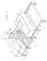
- the burial device shown in FIG. 1 has a frame 6 which is essentially formed from individual bars 4 joined together by plug-in connections 2 and which is carried by feet 8 at a distance above the ground 10. If desired, some or all of the bars 4 can be extended, as can the feet 8, for example by means of known ones Scaffolding of conventional clamp or screw connections, which can be displaceably attached to it and whose length can be adjusted in order to be able to adapt the frame 6 to the respective installation site with any graves, tombstones or the like which may already be present.
- the frame 6 surrounds the grave opening 12, over which it extends on both sides in the example shown.
- the frame sections extending beyond the grave opening 12 are, as far as desirable, made accessible by a plank covering 14.
- the frame On both sides of the digging opening 12, the frame carries 6 rails 16 for an earth excavator 18, here in the form of an upright chain milling machine, as is known, for example, from the aforementioned DE-A-21 53 908.
- This chain milling machine which extends over the entire width of the digging opening to be produced, can be moved in the longitudinal direction of the digging opening on the running rails 16 and, moreover, can be adjusted in depth in accordance with the progress of work.
- Drive means, guide means and the like can be detachable therefrom to facilitate their transport to and from the vehicle.
- the excavation device is preferably driven electrically, hydraulically or pneumatically, where the energy can come from an energy supply unit that is installed relatively distant if necessary.
- This energy supply unit can be part of a motor vehicle, which can also be set up to accommodate no individual parts of the entire device.
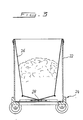
- the earth excavated by the excavation device 18 passes via a slide or a conveyor belt 20 into a receptacle 22 which can be moved on the frame 6 transversely to the digging opening 12 and which essentially consists of a sack 26 suspended in a carriage 24 with approximately the horizontal dimensions of the digging opening 12 exists.
- the bag 26 has in its bottom a gap-shaped opening 28 which extends over its entire length and which can be closed and opened by means of two bars 30 which can be approached and removed from one another.
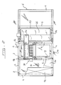
- the excavation device 18 according to FIG. 4 can be exchanged for a coffin sinking device 30 and can then immediately be used again in connection with a frame 6 already installed there.
- the coffin sinking device 30 need only be available for a short time.
- the coffin lowering device 30 can essentially be equipped, according to the aforementioned DE-A-91 254, with two drums 32 which are coupled in opposite directions and can be rotated with one another on both sides of the digging opening 23, from which belts 36 running under the coffin 34 can be unrolled.
- the belts can be provided with locks or can be uncoupled from one of the drums 32 in order to be able to pull them out again under the coffin lowered into the digging opening 12.
- the coffin lowering device 30 will be equipped with a suitable locking mechanism in a manner known per se.
- an electrical, hydraulic or pneumatic drive 38 which can be plugged on, as indicated by the broken line in FIG. 4.
- the frame sections which can be entered can be provided with a clip-on railing 40.
- the accessible frame sections as well as the digging opening 12 can be placed on the railing 40 or also directly on the frame 6 spanning canopy 42 are placed, consisting of a support frame 44, which itself is joined by a plug connection and which is covered with tarpaulin 46.
- Suitable hanging devices 48 on the railing 40 and / or the support frame 44 offer the possibility of hanging wreaths, bouquets or arrangements for the funeral ceremony.
- the canopy 42 and the railing 40 can be lifted off the frame 6 and the coffin sinking device 30 can also be removed, whereupon the receptacle 22 is moved in via the digging opening 12. Thereupon, only the bottom opening of the sack 26 needs to be opened in order to unload the soil taken up into the digging opening 12. Finally, the receptacle 22 and the frame 6 can also be removed from the grave in order to be used elsewhere, while in the region of the freshly created grave only minor leveling work remains to be done.
- the entire burial device described here can be easily dismantled into individual parts, which, if necessary, can be transported, assembled or stowed away by a single person, and that the device specified is a significant relief and rationalization for the entire burial process brings, but piety aspects can be taken into account in an optimal way.
Landscapes
- Engineering & Computer Science (AREA)
- Mining & Mineral Resources (AREA)
- Structural Engineering (AREA)
- Civil Engineering (AREA)
- General Engineering & Computer Science (AREA)
- Animal Behavior & Ethology (AREA)
- Health & Medical Sciences (AREA)
- Life Sciences & Earth Sciences (AREA)
- Mechanical Engineering (AREA)
- General Health & Medical Sciences (AREA)
- Public Health (AREA)
- Veterinary Medicine (AREA)
- Underground Structures, Protecting, Testing And Restoring Foundations (AREA)
- Investigation Of Foundation Soil And Reinforcement Of Foundation Soil By Compacting Or Drainage (AREA)
- Laying Of Electric Cables Or Lines Outside (AREA)
- Soil Working Implements (AREA)
- Catching Or Destruction (AREA)
- Management, Administration, Business Operations System, And Electronic Commerce (AREA)
Abstract
Description
- Die Erfindung betrifft ein zerlegbares Erdbestattungsgerät mit den Merkmalen des Gattungsbegriffs des Patentanspruchs 1.
- Ein solches Gerät ist aus der DE-B-26 25 082 bereits in einer Form bekannt, bei der auf dem betreffenden, die Graböffnung umgebenden und sich darüber hinauserstreckenden Rahmen ein Greiferbagger mit universell schwenkbarem Ausleger wie auch ein kippbarer kastenförmiger Aufnahmebehälter für das ausgehobene Erdreich stationär, wenngleich davon lösbar angebracht sind.
- Die DE-A-21 53 908 zeigt ein Grabaushubgerät, bei dem eine Kettenfräse mit vertikalen Trumen horizontal- wie vertikalbeweglich auf einem rahmenförmigen Fahrgestell angeordnet ist. Das Fahrgestell ist auf Füße absetzbar. Das ausgehobene Erdreich wird über eine Rutsche neben dem Fahrgestell abgeworfen.
- Schließlich sind aus der DE-A-91 254 und der DE-A-622 660 Sargversenkvorrichtungen bekannt, mit denen sich die Särge über von gegenläufig drehbaren Trommeln ablaufende Seile bzw. Gurte seitens einer einzigen Person in das Grab versenken lassen. Dabei werden die Trommeln wiederum von einem die Graböffnung umgebenden Rahmen getragen. Im Fall der DE-A-622 660 besteht dieser im übrigen zu Begräbniszwecken betretbare Rahmen aus kastenförmigen Elementen, die zum Teil das ausgehobene Erdreich aufnehmen. Zudem ist auf den Rahmen eine Art Pult für den Geistlichen aufsetztbar.
- Von diesem Stand der Technik ausgehend liegt der Erfindung die Aufgabe zugrunde, ein Erdbestattungsgerät nach Gattungsbegriff so auszubilden, daß es die Abwicklung einer Erdbestattung noch weitergehend erleichtert bis hin zur Grablegung und zur anschließenden Auffüllung des Grabes mit dem zuvor ausgehobenen Erdreich.
- Diese Aufgabe ist erfindungsgemäß durch das kennzeichnende Merkmal des Anspruchs 1 gelöst. Die Unteransprüche geben dar- über hinausgehende vorteilhafte Ausgestaltungsmöglichkeiten der Erfindung an.
- Die Austauschbarkeit des Erdaushubgeräts gegen die Sargversenkvorrichtung stellt eine zweifache Funktion des einmal aufgestellten Rahmens her, dessen Vorhandensein infolgedessen auch während der Beerdigungszeremonie nicht als störend empfunden wird. Dies gilt umso mehr, wenn der Rahmen - nach Anspruch 8 - begehbar ist oder - nach Anspruch 9 - darüber hinaus das Podest eines Baldachins bildet.
- Nach Entfernen des Erdaushubgeräts kann dieses sogleich anderenorts an einem dort bereits aufgestellten Rahmen zum Einsatz kommen, ebenso wie der Baldachin nur kurzzeitig zur Verfügung zu stehen braucht. In dieser Hinsicht kann es auf größeren Friedhöfen zweckmäßig sein, mit einem oder wenigen Erdaushubgeräten und/oder Baldachinen eine größere Zahl von Rahmen zum Einsatz zu bringen. Dabei kann ein Transportfahrzeug gute Dienste leisten, das, etwa einem Feuerwehrgerätefahrzeug vergleichbar, Aufnahmemittel oder zumindest Unterbringungsmöglichkeiten für die verschiedenen Einzelteile des betreffenden Erdbestattungsgeräts aufweist. Diese gilt umso mehr, wenn dieses Fahrzeug gemäß Anspruch 7 auch noch die Energieversorgung des Geräts übernimmt.
- Als besonders vorteilhaft hat sich ein auf dem Rahmen über die Graböffnung verfahrbarer und dort bodenseitig entleerbarer Aufnahmebehälter nach Anspruch 2 erwiesen, zumal wenn er so leicht und leicht handhabbar ist, wie diese die Ausbildung nach Anspruch 3 ergibt.
- Die Variationsmöglichkeit nach Anspruch 10 bewirkt, daß der betreffende Rahmen ungeachtet benachbarter bereits vorhandener Gräber oder selbst des Grabsteins des gerade betroffenen Grabes praktisch überall auf herkömmlichen Friedhöfen zum Einsatz kommen kann. Schließlich hat sich die Zusammenfügung der einzelnen Teile des Geräts über Steckverbindungen nach Anspruch 11 als besonders einfach und zweckmäßig erwiesen.
- Nachfolgend wird ein entsprechendes, bevorzugtes Ausführungsbeispiel der Erfindung anhand der Zeichnungen genauer beschrieben. Von diesen zeigt, jeweils in schematisierter Darstellung,
- Fig. 1 eine Gesamtansicht des betreffenden Erdbestattungsgeräts am Einsatzort mit angebrachtem Erdaushubgerät,
- Fig. 2 eine Draufsicht auf den Rahmen des Geräts,
- Fig. 3 einen Querschnitt durch den Aufnahmebehälter des Geräts und
- Fig. 4 das Gerät mit gegen eine Sargversenkvorrichtung ausgetauschtem Erdaushubgerät und aufgesetztem Baldachin.
- Das in Fig. 1 gezeigte Erdbestattungsgerät weist einen im wesentlichen aus einzelnen über Steckverbindungen 2 zusammengefügten Holmen 4 gebildeten Rahmen 6 auf, der von Füßen 8 in einem Abstand über dem Erdboden 10 getragen wird. Gewünschtenfalls können einzelne oder auch alle der Holme 4 verlängerbar sein, ebenso wie die Füße 8, etwa mittels bekannter, bei Baugerüsten üblicher Klemm- bzw. Schraubverbindungen, versetzbar daran angebracht und in ihrer Länge verstellbar sein können, um den Rahmen 6 dem jeweiligen Aufstellungsort mit ggf. bereits vorhandenen Gräbern, Grabsteinen oder dergl. anpassen zu können.
- Der Rahmen 6 umgibt die Graböffnung 12, über die er sich in dem gezeigten Beispiel beidseitig hinauserstreckt. Die sich über die Graböffnung 12 hinauserstreckenden Rahmenabschnitte sind, soweit wünschenwert, durch eine Plankeneindeckung 14 betretbar gemacht. Zu beiden Seiten der Graböffnung 12 trägt der Rahmen 6 Laufschienen 16 für ein Erdaushubgerät 18, hier in Gestalt einer aufrechtstehenden Kettenfräse, wie sie etwa aus der eingangs genannten DE-A-21 53 908 bekannt ist. Diese über die gesamte Breite der herzustellenden Graböffnung reichende Kettenfräse ist in Längsrichtung der Graböffnung auf den Laufschienen 16 verfahrbar und überdies entsprechend dem Arbeitsfortschritt in die Tiefe verstellbar. Zur Erleichterung ihres An- und Abtransports können Antriebsmittel, Führungsmittel und dergl. davon abtrennbar sein.
- Der Antrieb des Erdaushubgeräts erfolgt vorzugsweise elektrisch, hydraulisch oder auch pneumatisch, wobie die Energie einem erforderlichenfalls verhältnismäßig entfernt aufgestellten Energieversorgungsaggregat entstammen kann. Dieses Energieversorgungsaggregat kann Bestandteil eines Kraftfahrzeugs sein, das im übrigen dazu eingerichtet sein kann, kie einzelnen Bestandteile des gesamten Geräts aufzunehmen.
- Das von dem Erdaushubgerät 18 ausgehobene Erdreich gelangt über eine Rutsche oder ein Förderband 20 in einen auf dem Rahmen 6 quer zu der Graböffnung 12 verfahrbaren Aufnahmebehälter 22, der im wesentlichen aus einem in einen Wagen 24 eingehängten Sack 26 mit etwa den horizontalen Abmessungen der Graböffnung 12 besteht. Der Sack 26 besitzt in seinem Boden eine über seine gesamte Länge reichende spaltförmige Öffnung 28, die sich durch zwei einander näherbare und voneinander entfernbare Holme 30 schließen und öffnen läßt.
- Nach Beendigung des Erdaushubs ist das Erdaushubgerät 18 gemäß Fig. 4 gegen eine Sargversenkvorrichtung 30 auswechselbar und kann daraufhin sogleich anderenorts in Verbindung mit einem dort bereits aufgestellten Rahmen 6 wieder zum Einsatz kommen. Ebenso braucht auch die Sargversenkungsvorrichtung 30 nur kurzzeitig zur Verfügung zu stehen.
- Die Sargversenkvorrichtung 30 kann im wesentlichen nach der eingangs genannten DE-A-91 254 mit zwei gegenläufig drehbar miteinander gekuppelten Trommeln 32 zu beiden Seiten der Graböffnung 23 ausgestattet sein, von denen unter dem Sarg 34 hindurchlaufende Gurte 36 abrollbar sind. Die Gurte können mit Schlössern versehen oder aber von einer der Trommeln 32 abkuppelbar sein, um sie unter dem in die Graböffnung 12 abgesenkten Sarg wieder herausziehen zu können. Es versteht sich, daß die Sargversenkvorrichtung 30 in an sich bekannter Weise mit einem geeigneten Gesperre ausgerüstet sein wird. Auch kann sie in Anbetracht der ohnedies erforderlichen Energieversorgung des Erdaushubgeräts 18 gewünshchtenfalls ohne weiteres mit einem - ggf. aufsteckbaren - elektrischen, hydraulischen oder auch pneumatischen Antrieb 38 versehen sein, wie dies in Fig. 4 gestrichelt angedeutet ist.
- Nachdem der Aufnahmebehälter 22 für die Beerdigungszeremonie weiter von der Graböffnung 12 weggefahren und vorzugsweise abgedeckt worden ist, können die betretbaren Rahmenabschnitte mit einem aufsteckbaren Geländer 40 versehen werden. Ferner kann auf das Geländer 40 oder auch unmittelbar auf den Rahmen 6 ein die betretbaren Rahmenabschnitte wie auch die Graböffnung 12 überspannender Baldachin 42 aufgesetzt werden, bestehend aus einem selbst wiederum über Steckverbindung zusammengefügten Traggestell 44, das mit Planen 46 überzogen ist. Geeignete Aufhängvorrichtung 48 an dem Geländer 40 und/oder dem Traggestell 44 bieten die Möglichkeit, für die Beerdigungszeremonie Kränze, Bouquets oder Gestecke daran aufzuhängen.
- Nach Beendigung der Beerdigungszeremonie können Baldachin 42 und Geländer 40 von dem Rahmen 6 abgehoben und auch die Sargversenkvorrichtung 30 entfernt werden, worauf der Aufnahmebehälter 22 über die Graböffnung 12 eingefahren wird. Darauf braucht lediglich die bodenseitige Öffnung des Sackes 26 geöffnet zu werden, um das davon aufgenommene Erdreich in die Graböffnung 12 zu entladen. Schließlich können auch der Aufnahmebehälter 22 und der Rahmen 6 von dem Grab entfernt werden, um an anderer Stelle zum Einsatz zu kommen, während im Bereich des frisch entstandenen Grabes im wesentlichen nur geringfügige Einebnungsarbeiten zu verrichten bleiben.
- Bemerkenswert ist, daß sich das gesamte hier beschriebene Erdbestattungsgerät auf leichte Weise in einzelne Teile zerlegen läßt, die erforderlichenfalls von einer einzigen Person transportiert, zusammengesetzt oder auch verstaut werden können, und daß das angegebene Gerät eine wesentliche Erleichterung und Rationalisierung für den gesamten Beerdigungsablauf mit sich bringt, wobei indessen Pietätsgesichtspunkten in optimaler Weise Rechnung getragen werden kann.
Claims (12)
Priority Applications (1)
| Application Number | Priority Date | Filing Date | Title |
|---|---|---|---|
| AT89102607T ATE82028T1 (de) | 1988-02-15 | 1989-02-15 | Erdbestattungsgeraet. |
Applications Claiming Priority (2)
| Application Number | Priority Date | Filing Date | Title |
|---|---|---|---|
| DE3804719 | 1988-02-15 | ||
| DE3804719 | 1988-02-15 |
Publications (2)
| Publication Number | Publication Date |
|---|---|
| EP0329114A1 true EP0329114A1 (de) | 1989-08-23 |
| EP0329114B1 EP0329114B1 (de) | 1992-11-04 |
Family
ID=6347469
Family Applications (1)
| Application Number | Title | Priority Date | Filing Date |
|---|---|---|---|
| EP89102607A Expired - Lifetime EP0329114B1 (de) | 1988-02-15 | 1989-02-15 | Erdbestattungsgerät |
Country Status (5)
| Country | Link |
|---|---|
| EP (1) | EP0329114B1 (de) |
| AT (1) | ATE82028T1 (de) |
| DE (1) | DE58902581D1 (de) |
| ES (1) | ES2036727T3 (de) |
| GR (1) | GR3006993T3 (de) |
Cited By (4)
| Publication number | Priority date | Publication date | Assignee | Title |
|---|---|---|---|---|
| GB2229694A (en) * | 1989-03-28 | 1990-10-03 | Wilfred George Brian Coffin | Interment apparatus |
| DE19603824A1 (de) * | 1996-02-02 | 1997-08-14 | Bruemmer Benno | Bagger, insbesondere Friedhofsbagger |
| US20150191930A1 (en) * | 2014-01-06 | 2015-07-09 | Stephen Sabo, JR. | Platform for a cemetery lowering device |
| CN110623800A (zh) * | 2019-10-17 | 2019-12-31 | 中国人民解放军空军工程大学 | 一种轮椅 |
Citations (4)
| Publication number | Priority date | Publication date | Assignee | Title |
|---|---|---|---|---|
| FR786451A (fr) * | 1935-03-01 | 1935-09-03 | Perfectionnements aux appareils destinés à descendre les cercueils dans les fosses communes | |
| CH470542A (de) * | 1968-06-19 | 1969-03-31 | Menzi Ag Ernst | Unterstützkonstruktion für einen Bagger |
| FR2254687A1 (de) * | 1973-12-15 | 1975-07-11 | Boos Hans | |
| GB2009680A (en) * | 1977-12-08 | 1979-06-20 | Case Co J I | Main frame constructions for vehicles |
-
1989
- 1989-02-15 DE DE8989102607T patent/DE58902581D1/de not_active Expired - Lifetime
- 1989-02-15 EP EP89102607A patent/EP0329114B1/de not_active Expired - Lifetime
- 1989-02-15 ES ES198989102607T patent/ES2036727T3/es not_active Expired - Lifetime
- 1989-02-15 AT AT89102607T patent/ATE82028T1/de not_active IP Right Cessation
-
1993
- 1993-02-05 GR GR930400239T patent/GR3006993T3/el unknown
Patent Citations (4)
| Publication number | Priority date | Publication date | Assignee | Title |
|---|---|---|---|---|
| FR786451A (fr) * | 1935-03-01 | 1935-09-03 | Perfectionnements aux appareils destinés à descendre les cercueils dans les fosses communes | |
| CH470542A (de) * | 1968-06-19 | 1969-03-31 | Menzi Ag Ernst | Unterstützkonstruktion für einen Bagger |
| FR2254687A1 (de) * | 1973-12-15 | 1975-07-11 | Boos Hans | |
| GB2009680A (en) * | 1977-12-08 | 1979-06-20 | Case Co J I | Main frame constructions for vehicles |
Cited By (6)
| Publication number | Priority date | Publication date | Assignee | Title |
|---|---|---|---|---|
| GB2229694A (en) * | 1989-03-28 | 1990-10-03 | Wilfred George Brian Coffin | Interment apparatus |
| DE19603824A1 (de) * | 1996-02-02 | 1997-08-14 | Bruemmer Benno | Bagger, insbesondere Friedhofsbagger |
| DE19603824C2 (de) * | 1996-02-02 | 1999-04-29 | Bruemmer Benno | Bagger, insbesondere Friedhofsbagger |
| US20150191930A1 (en) * | 2014-01-06 | 2015-07-09 | Stephen Sabo, JR. | Platform for a cemetery lowering device |
| US9567766B2 (en) * | 2014-01-06 | 2017-02-14 | Stephen Sabo, JR. | Platform for a cemetery lowering device |
| CN110623800A (zh) * | 2019-10-17 | 2019-12-31 | 中国人民解放军空军工程大学 | 一种轮椅 |
Also Published As
| Publication number | Publication date |
|---|---|
| DE58902581D1 (de) | 1992-12-10 |
| ES2036727T3 (es) | 1993-06-01 |
| EP0329114B1 (de) | 1992-11-04 |
| ATE82028T1 (de) | 1992-11-15 |
| GR3006993T3 (de) | 1993-06-30 |
Similar Documents
| Publication | Publication Date | Title |
|---|---|---|
| DE2749470C3 (de) | Brückenbesichtigungs- und -wartungsvorrichtung | |
| DE69012875T2 (de) | Rettungsgestell. | |
| DE3013513A1 (de) | Umruestbare maschine mit einem ausleger | |
| DE3008380A1 (de) | Verfahren und vorrichtung zum kontinuierlichen ausheben von erdreich und foerdern des aushubmaterials in vertikaler richtung | |
| EP0329114B1 (de) | Erdbestattungsgerät | |
| EP0105504B1 (de) | Verfahren und Vorrichtung zum Demontieren von Deckenschalungen | |
| DE102008061334A1 (de) | Vorrichtung zur Handhabung von schweren Gegenständen | |
| DE1158663B (de) | Operationstisch | |
| DE2845222A1 (de) | Baumfaeller | |
| DE102004033706B4 (de) | Vorrichtung zum Niederbringen von Gründungsbohrungen | |
| DE202016103063U1 (de) | Vorrichtung zur Entleerung eines Industriesaugers | |
| DE19948938A1 (de) | Vorrichtung zum Einfüllen von Beton aus einem Betonkübel in eine Schalung | |
| DE2625082C3 (de) | ||
| DE8807375U1 (de) | Totengräbermaschine mit Trägerpodest | |
| DE688714C (de) | Vorrichtung zum Ausheben des Schlammes aus Wassergraeben und zum Verteilen des ausgehobenen Schlammes mit einem von Hand zu fuehrenden hochwindbaren Schoepfeimer | |
| DE847796C (de) | Versenk-, Hebe- und/oder Transportvorrichtung, insbesondere fuer Saerge | |
| DE837377C (de) | Saugbagger | |
| DE2263157B1 (de) | Kran, insbesondere Laufkatzen Auslegerturmkran | |
| DE943196C (de) | Fahrzeug mit auswechselbaren, insbesondere landwirtschaftlichen Arbeitsgeraeten | |
| WO2004076255A1 (de) | Verfahrbare maschine mit arbeitsgeräten auf dem maschinenchassis und bodenabstützungen | |
| DE9003126U1 (de) | Arbeitstisch | |
| DE8327962U1 (de) | Ziehvorrichtung zum herausziehen eines kastenrahmenfoermigen grabverbaus | |
| DE3610814A1 (de) | Fahrbares bohr-, ramm- oder dergleichen geraet | |
| DE1708572C3 (de) | Schachteinrichtung | |
| DE4437858A1 (de) | Verfahren und Vorrichtung zum Erstellen von transportablen vertikalen Wänden bzw. Wandteilen aus Mauersteinen |
Legal Events
| Date | Code | Title | Description |
|---|---|---|---|
| PUAI | Public reference made under article 153(3) epc to a published international application that has entered the european phase |
Free format text: ORIGINAL CODE: 0009012 |
|
| AK | Designated contracting states |
Kind code of ref document: A1 Designated state(s): AT BE CH DE ES FR GB GR IT LI LU NL SE |
|
| 17P | Request for examination filed |
Effective date: 19900213 |
|
| 17Q | First examination report despatched |
Effective date: 19901219 |
|
| GRAA | (expected) grant |
Free format text: ORIGINAL CODE: 0009210 |
|
| AK | Designated contracting states |
Kind code of ref document: B1 Designated state(s): AT BE CH DE ES FR GB GR IT LI LU NL SE |
|
| REF | Corresponds to: |
Ref document number: 82028 Country of ref document: AT Date of ref document: 19921115 Kind code of ref document: T |
|
| REF | Corresponds to: |
Ref document number: 58902581 Country of ref document: DE Date of ref document: 19921210 |
|
| ITF | It: translation for a ep patent filed | ||
| ET | Fr: translation filed | ||
| GBT | Gb: translation of ep patent filed (gb section 77(6)(a)/1977) |
Effective date: 19930217 |
|
| REG | Reference to a national code |
Ref country code: GR Ref legal event code: FG4A Free format text: 3006993 |
|
| REG | Reference to a national code |
Ref country code: ES Ref legal event code: FG2A Ref document number: 2036727 Country of ref document: ES Kind code of ref document: T3 |
|
| PLBE | No opposition filed within time limit |
Free format text: ORIGINAL CODE: 0009261 |
|
| STAA | Information on the status of an ep patent application or granted ep patent |
Free format text: STATUS: NO OPPOSITION FILED WITHIN TIME LIMIT |
|
| 26N | No opposition filed | ||
| PGFP | Annual fee paid to national office [announced via postgrant information from national office to epo] |
Ref country code: GB Payment date: 19940228 Year of fee payment: 6 |
|
| PGFP | Annual fee paid to national office [announced via postgrant information from national office to epo] |
Ref country code: ES Payment date: 19940323 Year of fee payment: 6 |
|
| EPTA | Lu: last paid annual fee | ||
| EAL | Se: european patent in force in sweden |
Ref document number: 89102607.2 |
|
| PGFP | Annual fee paid to national office [announced via postgrant information from national office to epo] |
Ref country code: LU Payment date: 19950201 Year of fee payment: 7 |
|
| PGFP | Annual fee paid to national office [announced via postgrant information from national office to epo] |
Ref country code: FR Payment date: 19950214 Year of fee payment: 7 |
|
| PG25 | Lapsed in a contracting state [announced via postgrant information from national office to epo] |
Ref country code: GB Effective date: 19950215 |
|
| PG25 | Lapsed in a contracting state [announced via postgrant information from national office to epo] |
Ref country code: ES Free format text: LAPSE BECAUSE OF NON-PAYMENT OF DUE FEES Effective date: 19950216 |
|
| PGFP | Annual fee paid to national office [announced via postgrant information from national office to epo] |
Ref country code: BE Payment date: 19950221 Year of fee payment: 7 |
|
| PGFP | Annual fee paid to national office [announced via postgrant information from national office to epo] |
Ref country code: GR Payment date: 19950223 Year of fee payment: 7 |
|
| PGFP | Annual fee paid to national office [announced via postgrant information from national office to epo] |
Ref country code: SE Payment date: 19950224 Year of fee payment: 7 Ref country code: AT Payment date: 19950224 Year of fee payment: 7 |
|
| PGFP | Annual fee paid to national office [announced via postgrant information from national office to epo] |
Ref country code: NL Payment date: 19950228 Year of fee payment: 7 |
|
| PGFP | Annual fee paid to national office [announced via postgrant information from national office to epo] |
Ref country code: DE Payment date: 19950317 Year of fee payment: 7 |
|
| PGFP | Annual fee paid to national office [announced via postgrant information from national office to epo] |
Ref country code: CH Payment date: 19950327 Year of fee payment: 7 |
|
| GBPC | Gb: european patent ceased through non-payment of renewal fee |
Effective date: 19950215 |
|
| PG25 | Lapsed in a contracting state [announced via postgrant information from national office to epo] |
Ref country code: LU Free format text: LAPSE BECAUSE OF NON-PAYMENT OF DUE FEES Effective date: 19960215 Ref country code: AT Effective date: 19960215 |
|
| PG25 | Lapsed in a contracting state [announced via postgrant information from national office to epo] |
Ref country code: SE Free format text: THE PATENT HAS BEEN ANNULLED BY A DECISION OF A NATIONAL AUTHORITY Effective date: 19960227 |
|
| PG25 | Lapsed in a contracting state [announced via postgrant information from national office to epo] |
Ref country code: LI Free format text: LAPSE BECAUSE OF NON-PAYMENT OF DUE FEES Effective date: 19960228 Ref country code: CH Free format text: LAPSE BECAUSE OF NON-PAYMENT OF DUE FEES Effective date: 19960228 Ref country code: BE Effective date: 19960228 |
|
| BERE | Be: lapsed |
Owner name: MATULA FRANZ Effective date: 19960228 |
|
| PG25 | Lapsed in a contracting state [announced via postgrant information from national office to epo] |
Ref country code: GR Free format text: THE PATENT HAS BEEN ANNULLED BY A DECISION OF A NATIONAL AUTHORITY Effective date: 19960831 |
|
| PG25 | Lapsed in a contracting state [announced via postgrant information from national office to epo] |
Ref country code: NL Effective date: 19960901 |
|
| REG | Reference to a national code |
Ref country code: CH Ref legal event code: PL |
|
| PG25 | Lapsed in a contracting state [announced via postgrant information from national office to epo] |
Ref country code: FR Effective date: 19961031 |
|
| REG | Reference to a national code |
Ref country code: GR Ref legal event code: MM2A Free format text: 3006993 |
|
| NLV4 | Nl: lapsed or anulled due to non-payment of the annual fee |
Effective date: 19960901 |
|
| PG25 | Lapsed in a contracting state [announced via postgrant information from national office to epo] |
Ref country code: DE Effective date: 19961101 |
|
| REG | Reference to a national code |
Ref country code: FR Ref legal event code: ST |
|
| REG | Reference to a national code |
Ref country code: ES Ref legal event code: FD2A Effective date: 19990405 |
|
| PG25 | Lapsed in a contracting state [announced via postgrant information from national office to epo] |
Ref country code: IT Free format text: LAPSE BECAUSE OF NON-PAYMENT OF DUE FEES;WARNING: LAPSES OF ITALIAN PATENTS WITH EFFECTIVE DATE BEFORE 2007 MAY HAVE OCCURRED AT ANY TIME BEFORE 2007. THE CORRECT EFFECTIVE DATE MAY BE DIFFERENT FROM THE ONE RECORDED. Effective date: 20050215 |