EP0329829A2 - Vorrichtung zum flächigen Auftragen von Leim oder dergleichen - Google Patents
Vorrichtung zum flächigen Auftragen von Leim oder dergleichen Download PDFInfo
- Publication number
- EP0329829A2 EP0329829A2 EP88117966A EP88117966A EP0329829A2 EP 0329829 A2 EP0329829 A2 EP 0329829A2 EP 88117966 A EP88117966 A EP 88117966A EP 88117966 A EP88117966 A EP 88117966A EP 0329829 A2 EP0329829 A2 EP 0329829A2
- Authority
- EP
- European Patent Office
- Prior art keywords
- glue
- channels
- application
- substrate
- individual
- Prior art date
- Legal status (The legal status is an assumption and is not a legal conclusion. Google has not performed a legal analysis and makes no representation as to the accuracy of the status listed.)
- Granted
Links
Images

Classifications
-
- B—PERFORMING OPERATIONS; TRANSPORTING
- B05—SPRAYING OR ATOMISING IN GENERAL; APPLYING FLUENT MATERIALS TO SURFACES, IN GENERAL
- B05C—APPARATUS FOR APPLYING FLUENT MATERIALS TO SURFACES, IN GENERAL
- B05C5/00—Apparatus in which liquid or other fluent material is projected, poured or allowed to flow on to the surface of the work
- B05C5/02—Apparatus in which liquid or other fluent material is projected, poured or allowed to flow on to the surface of the work the liquid or other fluent material being discharged through an outlet orifice by pressure, e.g. from an outlet device in contact or almost in contact, with the work
- B05C5/027—Coating heads with several outlets, e.g. aligned transversally to the moving direction of a web to be coated
- B05C5/0275—Coating heads with several outlets, e.g. aligned transversally to the moving direction of a web to be coated flow controlled, e.g. by a valve
- B05C5/0279—Coating heads with several outlets, e.g. aligned transversally to the moving direction of a web to be coated flow controlled, e.g. by a valve independently, e.g. individually, flow controlled
-
- B—PERFORMING OPERATIONS; TRANSPORTING
- B05—SPRAYING OR ATOMISING IN GENERAL; APPLYING FLUENT MATERIALS TO SURFACES, IN GENERAL
- B05C—APPARATUS FOR APPLYING FLUENT MATERIALS TO SURFACES, IN GENERAL
- B05C5/00—Apparatus in which liquid or other fluent material is projected, poured or allowed to flow on to the surface of the work
- B05C5/02—Apparatus in which liquid or other fluent material is projected, poured or allowed to flow on to the surface of the work the liquid or other fluent material being discharged through an outlet orifice by pressure, e.g. from an outlet device in contact or almost in contact, with the work
- B05C5/0254—Coating heads with slot-shaped outlet
-
- B—PERFORMING OPERATIONS; TRANSPORTING
- B05—SPRAYING OR ATOMISING IN GENERAL; APPLYING FLUENT MATERIALS TO SURFACES, IN GENERAL
- B05C—APPARATUS FOR APPLYING FLUENT MATERIALS TO SURFACES, IN GENERAL
- B05C5/00—Apparatus in which liquid or other fluent material is projected, poured or allowed to flow on to the surface of the work
- B05C5/02—Apparatus in which liquid or other fluent material is projected, poured or allowed to flow on to the surface of the work the liquid or other fluent material being discharged through an outlet orifice by pressure, e.g. from an outlet device in contact or almost in contact, with the work
- B05C5/0254—Coating heads with slot-shaped outlet
- B05C5/0258—Coating heads with slot-shaped outlet flow controlled, e.g. by a valve
Definitions
- the invention relates to a device of the type corresponding to the preamble of claim 1.
- the starting point of the invention has been problems which occurred during the production of hygiene articles.
- articles such as diaper pants for babies, diaper pads, sanitary napkins, medical pads, surgical pads and the like, which are used to collect liquid separated from the body and on one side a liquid-impermeable, very flexible film of low thickness, for example made of polypropylene of 12 to 15 My ( Micrometers) to which a flat suction pad made of cellulose or a suitable plastic material is glued, which in turn is covered by a fleece.
- the suction pad consists of a loose material in the manner of a short-fiber cotton, which must be fixed on the film so that it stays in place and does not slip when handling the article. For this reason, the suction pad is glued to the film.
- a reasonably uniform distribution requires, in particular, a low viscosity of the hot-melt adhesive, which was therefore applied at temperatures of 110 to 140 ° C.
- the uniformity was unsatisfactory.
- the object of the invention is to design a generic device such that very small application quantities per unit area can be applied particularly uniformly to a leading substrate across its width.
- a slot nozzle should be hydrodynamically preferred because, for example, due to manufacturing tolerances, it has a slightly larger slot width, or because of Flow resistance of the channels up to the slot nozzle is somewhat lower, so this slot nozzle will only release exactly the amount of the order assigned by the pump assigned to it. If there is such a hydrodynamically preferred area in the case of a slot nozzle which extends over the entire application width, the application quantity preferably emerges at this point and the pressure drops sharply towards the sides, as a result of which different application quantities per unit area cannot be avoided.
- the glue has to be applied to a sensitive film
- the application quantity can be reduced to an amount of 0.2 g / m2. Quite apart from the saving of glue, this has the effect that the heat capacity of the applied glue is very low and thus the thermal load on the substrate, i.e. the film remains low.
- Another factor works in the same direction, namely that in order to even out the application, it is no longer necessary to ensure that the glue has as low a viscosity as possible with a continuous slot nozzle.
- the application is also even when applied with a slightly higher viscosity. This means that the temperature of the glue can be reduced to values around 65 ° C without loss of uniformity, which also reduces the stress on the film.
- gluing of the film for the hygiene articles mentioned is the starting point and preferred example of application of the invention, but it is understood that the device can also be used for substrates other than those mentioned Foils can be used, especially for even application of very small amounts of glue. Glue is also only the preferred application of the invention and other liquid to highly viscous application agents are by no means excluded.
- the separate glue pumps assigned to the individual slit nozzles can be provided in the form of a multiple pump, in which, if it is designed as a gear pump, a corresponding number of planetary counter gears, for example, working against a common central wheel, produce cleanly separated flow rates.
- the adjacent individual slot nozzles can be formed in the manner set out in claim 3.
- the two "surfaces” are formed, for example, by an end face of a nozzle plate provided on the device, in which the feed channels open, and a clamping strip extending in front of it, which clamp the slotted plate between them.
- the feed channels open into the areas of the slotted plate that remain free between the webs, so that the glue is channeled through the back of the slotted plate and the webs, and the individual glue flows are only combined immediately before the exit point, so that on the one hand there is a uniform coverage of the application width , a transfer of glue from a slot nozzle into the neighboring one is practically prevented.
- the nozzle plate is an integral part of the device, as a result of which a distribution of the outlet openings of the feed channels in the end face of the nozzle plate is predetermined at certain distances in the direction of the application width. Now it may happen that the order width has to be changed.
- the embodiment shown in claim 5 in the form of the intermediate plate is used, with the aid of which the exit points of the feed channels opening into the individual slot nozzles can be pulled apart or pushed together.
- the slotted plate and the intermediate plate are replaced, and it is therefore possible to work with eight slit nozzles of, for example, 35 mm wide instead of eight slit nozzles each 30 mm in width, without any assembly work other than unscrewing the terminal strip and replacing the slit plate and the intermediate plate are required.
- the device 100 shown in FIGS. 1 and 2 is used to provide the film web 1 with a very thin layer of hot-melt adhesive over an application width 2 (FIG. 2) evenly.
- the film web 1 consists of polypropylene of 15 my thickness and is guided past the exit point 3 of the hot-melt adhesive in the manner shown in FIG. 1 with a slight wrap angle and a slight longitudinal tension. The film web 1 is therefore not supported at the exit point 3.
- the device 100 comprises an application head, designated as a whole by 4, and this in turn comprises an application block 5 with inner channels, which are shown in detail in FIG. 3.
- the application block 5 is held by two side walls 6, which are connected by a cross plate 7, which in turn is fastened in a suitable manner above the film web 1 in the machine frame.
- a drive motor 8 is fastened to the cross plate 7 and drives an eightfold gear pump 10 mounted on the order block 5 via an angular gear 9.
- the eightfold gear pump 10 comprises eight individual gear pumps which generate eight metered glue flows which are independent of one another and which are passed through inner channels into the application block 5.
- the liquid glue brought up from a melting device, not shown, passes through one Filter 11 and enters the order block 5 at the channel 12 and at the mouth 13 into the eightfold gear pump 10, which dispenses the glue in eight mutually independent streams into eight vertical channels 14 according to FIG. 3, across the width the web are distributed in the order block 5 attached.
- An order valve 15 is assigned to each channel 14 and is connected to the channel 14 via a transverse channel 17.
- each channel 14 is assigned a return valve 16 arranged above the application valve 15, which is connected to the channel 14 via a transverse channel 18.
- a glue return 20 is also connected to the return valve 16 via a transverse channel 19.
- the valves 15, 16 have the same design in terms of their hydrodynamic resistance and are pneumatically controlled.
- the air supply lines are labeled 21 and 22, respectively.
- the design is such that the valves 15, 16 are always actuated alternately, ie when the application valve 15 closes, the return valve 16 opens and leaves the glue conveyed in by the pump 10 in the channel 14 instead of via the transverse channel 17 to the application valve 15 via the cross channel 18 to the return valve 16, which is then open and passes the glue into the glue return 20. In this way, a glue flow of constant pressure can be maintained in the channel 14 regardless of the actuation of the application valve 15, in which no pressure surges occur due to the closing of the application valve 15.
- valve pairs 15, 16 are provided next to one another in accordance with the number of channels 14.
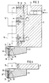
- a nozzle plate 23 is screwed under the application block 5 and the application valve 15, which has a vertical or essentially end face 24 which extends substantially perpendicular to the substrate and into which eight glue channels 25, which start from the respective outlet mouth of the application valves 15, open .
- a slotted plate 30 is arranged in front of the end face 24, the shape of which can be seen in FIG. 5 and which is screwed against the end face 24 by a clamping strip 26 with a flat rear face 27.
- the end face 24 and the rear face 27 have lower edges 28 and 29, respectively, which are at the same height.
- the slotted plate 30 is made of brass or corrosion-resistant steel and has a thickness of 0.3 mm. It covers the end face 24.
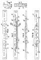
- a rectangular cutout 31 is formed, which extends over the application width 2 (FIG. 2) and which, in the exemplary embodiment, has eight webs 32 protruding into the cutout 31 in the embodiment by seven comb teeth which are arranged at equal intervals Chambers 33 is divided.
- the webs 32 are about 1 mm wide and tapered at the front.
- the tip lies at a short distance 34 (FIG. 6), for example 1 mm, above the lower edge 28 of the end face 24 when the slotted plate 30 is mounted in the manner shown in FIG. 3.
- the chambers 33 are closed on three sides, but open at the bottom and, together with the surfaces 24 and 27, form downwardly opening, separate slot nozzles 35 (FIG. 2).
- the valves 15, 16 are arranged close to each other. Their width is essentially fixed, so that a certain transverse distance between the glue channels 25 cannot be undershot. If the Order width 2 is dimensioned so that the division of the glue channels 25 coincides with the division of the slot nozzles 35, the glue channels 25 can open directly into the slot nozzles 35 formed, as shown in Fig. 3.
- the intermediate plate 40 has the same outline as the end face 24 or the slotted plate 30.
- the webs 32 On the front side shown in FIG. 7, in the longitudinal direction of the intermediate plate 40 extending but separate expansion grooves 36 are provided, the length of the width of the chambers 33 of the slotted plate 30 correspond.
- the webs 32 In the assembled state according to FIG. 4, the webs 32 each extend at the locations of the interruptions between successive spreading grooves 36.
- the middle six spreading grooves 36 have through bores 37 in the middle, which pass through to the rear side of the intermediate plate 40 shown in FIG. 10 . From the mouths of the through bores 37 on the back, angled channels 38, formed as grooves, lead to the points 39, which lie opposite the mouths of the glue channels 25 in the end face 24 of the nozzle plate 23.
- the locations 39 have the distance from one another corresponding to the glue channels 25, the through bores 37 have the distance given by the slot nozzles 35.
- the associated channel 38 ' is arranged for spatial reasons on the front side of the intermediate plate 40 shown in FIG. 7.
- the openings of the through bores 37 in the spreading grooves 36 are denoted by 41 in FIG. 9.
Landscapes
- Coating Apparatus (AREA)
- Application Of Or Painting With Fluid Materials (AREA)
Abstract
Description
- Die Erfindung bezieht sich auf eine Vorrichtung der dem Oberbegriff des Anspruchs 1 entsprechenden Art.
- Ausgangspunkt der Erfindung sind Probleme gewesen, die bei der Herstellung von Hygieneartikeln auftraten. Darunter sollen Artikel wie Windelhöschen für Babys, Windeleinlagen, Damenbinden, Krankenunterlagen, Operationsauflagen und dergleichen verstanden werden, die zum Auffangen vom Körper abgesonderter Flüssigkeit dienen und auf einer Seite eine flüssigkeitsundurchlässige sehr biegeschlaffe Folie von geringer Stärke, beispielsweise aus Polypropylen von 12 bis 15 My (Mikrometer) aufweisen, auf die ein flächiges Saugpolster aus Cellulose oder einem geeigneten Kunststoffmaterial aufgeklebt ist, welches seinerseits wiederum durch ein Vlies abgedeckt ist.
- Das Saugpolster besteht aus einemlosen Material nach Art einer kurzfasrigen Watte, welches auf der Folie fixiert werden muß, damit es seine Lage beibehält und bei der Handhabung des Artikels nicht verrutscht. Aus diesem Grund erfolgt die Verklebung des Saugpolsters mit der Folie.
- Die Schwierigkeit bei dieser Verklebung rührt daher, daß die Folie, auf die der Leim aufgetragen werden muß, sowohl mechanisch als auch thermisch sehr empfindlich ist. Aus diesem Grunde ist es schon unternommen worden, die Verklebung mit Kaltleim vorzunehmen. Kaltleim ist jedoch eine wäßrige Dispersion, und es besteht daher die Gefahr, daß bei absolut dichten Endverpackungen Probleme mit einem eventuellen Feuchtigkeitseinschluß auftreten. Die Alternative ist die Verwendung von Heißschmelzkleber, bei dem aber die gleichmäßige Verteilung einer geringen Auftragsmenge über die Auftragsbreite, die im allgemeinen im Bereich von 200 bis 800 mm liegt, Schwierigkeiten bereitet. Wenn, wovon im Oberbegriff ausgegangen wird, ein Auftrag mit einer einheitlichen, über die Auftragsbreite durchgehenden Auftragsdüse erfolgt, muß ein erheblicher Aufwand getrieben werden, um den Leim bei der geringen Menge gleichmäßig aus der Schlitzdüse austreten zu lassen. Eine einigermaßen gleichmäßige Verteilung verlangt insbesondere eine geringe Viskosität des Heißschmelzklebers, der aus diesem Grunde bei Temperaturen von 110 bis 140° C aufgetragen wurde. Dennoch war die Gleichmäßigkeit nicht zufriedenstellend. Die hohe Temperatur des aufgetragenen Heißleims und die bisher nicht unterschreitbare Auftragsmenge von 2 bis 4 g/m² führten dazu, daß sich die Folie stark verformte und die Rückseite des hergestellten Hygieneartikels ein unregelmäßig welliges Relief aufwies.
- Ebenfalls praktiziert wird das Verfahren, auf die Folie nur mit Abständen nebeneinandergelegte einzelne schmale Leimspuren aufzubringen. Diese Leimspuren prägen sich indessen auf der Rückseite der Folie ebenfalls deutlich aus und sind auch insofern nachteilig, als sich zwischen den Leimspuren Kanäle bilden, in denen das Saugpolster nicht mit der Folie verbunden ist und durch die Flüssigkeit, wie die Erfahrung zeigt, entweichen kann.
- Ausgehend von der geschilderten Problemlage liegt der Erfindung die Aufgabe zugrunde, eine gattungsgemäße Vorrichtung dahin auszugestalten, daß mit ihr sehr geringe Auftragsmengen pro Flächeneinheit auf ein vorlaufendes Substrat über dessen Breite besonders gleichmäßig aufgebracht werden können.
- Diese Aufgabe wird durch die in Anspruch 1 wiedergegebene Erfindung gelöst.
- Es wird also nicht mehr mit einer über die Auftragsbreite durchgehenden Schlitzdüse gearbeitet, bei der es sehr schwierig ist, über die ganze Länge überall gleichmäßige Austrittsmengen zu erhalten, sondern es wird eine Anzahl von schmäleren Schlitzdüsen nebeneinandergesetzt, sodaß die Breite der einzelnen Schlitzdüse entsprechend geringer wird. Bei einer Auftragsbreite von etwa 240 mm können beispielsweise acht einzelne Schlitzdüsen von je 30 mm Breite vorhanden sein. Innerhalb einer derartig schmalen einzelnen Schlitzdüse ist die gleichmäßige Verteilung über die Breite noch kein großes Problem. Der wesentliche Punkt ist aber, daß diese einzelnen Schlitzdüsen auch jeweils eine eigene Leimpumpe haben und nicht etwa über einen Verteilerkopf von einer gemeinsamen Leimpumpe versorgt werden. Durch diese Maßnahme ist sichergestellt, daß jeder einzelnen Schlitzdüse stets die gleiche Leimmenge zugeteilt wird und die Verteilung über die gesamte Auftragsbreite entsprechend gleichmäßig ist. Wenn nämlich eine Schlitzdüse hydrodynamisch bevorzugt sein sollte, weil sie beispielsweise, bedingt durch Fertigungstoleranzen, eine etwas größere Schlitzweite aufweist, oder weil der Strömungswiderstand der Kanäle bis zur Schlitzdüse etwas geringer ist, so wird trotzdem durch diese Schlitzdüse nur genau die durch die ihr zugeordnete Pumpe zugemessene Auftragsmenge austreten. Wenn bei einer über die ganze Auftragsbreite durchgehenden Schlitzdüse ein solcher hydrodynamisch bevorzugter Bereich vorhanden ist, tritt die Auftragsmenge bevorzugt an dieser Stelle aus und fällt der Druck nach den Seiten hin stark ab, wodurch unterschiedliche Auftragsmengen pro Flächeneinheit nicht zu vermeiden sind.
- Im Hinblick auf die erwähnten Hygieneartikel, bei denen der Leim auf eine empfindliche Folie aufgetragen werden muß, ergeben sich zwei wichtige Vorteile. Die Versuche haben gezeigt, daß die Auftragsmenge auf einen Betrag von 0,2 g/m² gesenkt werden kann. Dies wirkt sich, ganz abgesehen von der Leimersparnis, dahingehend aus, daß die Wärmekapazität des aufgetragenen Leims sehr gering ist und dadurch die thermische Belastung des Substrats, d.h. der Folie, gering bleibt. In der gleichen Richtung wirkt ein weiterer Umstand, nämlich daß zur Vergleichmäßigung des Auftrags nun nicht mehr wie bei einer durchgehenden Schlitzdüse auf eine möglichst geringe Viskosität des Leims geachtet werden muß. Der Auftrag ist auch noch gleichmäßig, wenn mit einer etwas höheren Viskosität aufgetragen wird. Das bedeutet, daß die Temperatur des Leims ohne Einbuße an Gleichmäßigkeit auf Werte um 65° C herabgesetzt werden kann, wodurch ebenfalls die Belastung der Folie vermindert wird.
- Die Beleimung der Folie bei den erwähnten Hygieneartikeln ist zwar Ausgangspunkt und bevorzugtes Anwendungsbeispiel der Erfindung, doch versteht es sich, daß die Vorrichtung auch für andere Substrate als die erwähnten Folien anwendbar ist, insbesondere zum gleichmäßigen Auftrag sehr geringer Leimmengen. Ebenso ist Leim nur der bevorzugte Anwendungsfall der Erfindung und sind andere flüssige bis hochviskose Auftragsmittel keinesfalls ausgeschlossen.
- Gemäß Anspruch 2 können die den einzelnen Schlitzdüsen zugeordneten separaten Leimpumpen in Gestalt einer Mehrfachpumpe vorgesehen sein, bei der, wenn sie als Zahnradpumpe ausgebildet ist, beispielsweise gegen ein gemeinsames Zentralrad eine entsprechende Anzahl planetenartig angeordneter Gegenzahnräder arbeitet, die sauber getrennte Förderströme erzeugen.
- Die einander benachbarten einzelnen Schlitzdüsen können in der in Anspruch 3 wiedergegebenen Weise gebildet sein.
- Die beiden "Flächen" sind hierbei beispielsweise durch eine Stirnfläche einer an der Vorrichtung vorgesehenen Düsenplatte, in der die Zuführkanäle ausmünden, und eine sich davor erstreckende Klemmleiste gebildet, die das Schlitzblech zwischen sich einspannen. Die Zuführkanäle münden in den zwischen den Stegen frei bleibenden Bereichen des Schlitzbleches, so daß der Leim durch den Rücken des Schlitzbleches und die Stege kanalisiert wird und eine Vereinigung der einzelnen Leimströme erst unmittelbar vor der Austrittsstelle stattfindet, so daß einerseits eine gleichmäßige Überdeckung der Auftragsbreite stattfindet, ein Übertritt von Leim von einer Schlitzdüse in die benachbarte aber praktisch unterbunden ist.
- Es empfiehlt sich, die Stege gemäß Anspruch 4 gegen die Austrittsstelle hin zuzuspitzen, damit die einzelnen Leimströme leicht ineinander übergehen können.
- In der Praxis ist die Düsenplatte fester Bestandteil der Vorrichtung, wodurch eine Verteilung der Austrittsmündungen der Zuführkanäle in der Stirnseite der Düsenplatte mit bestimmten Abständen in Richtung der Auftragsbreite vorgegeben ist. Es mag nun aber vorkommen, daß die Auftragsbreite geändert werden muß. Zur Bewältigung dieser Aufgabe dient die in Anspruch 5 wiedergegebene Ausgestaltung in Gestalt der Zwischenplatte, mit deren Hilfe die Austrittsstellen der in die einzelnen Schlitzdüsen mündenden Zuführkanäle auseinandergezogen oder zusammengedrängt werden können. Es werden also in einem solchen Bedarfsfall das Schlitzblech und die Zwischenplatte ausgewechselt, und es kann dadurch anstatt mit acht Schlitzdüsen à 30 mm Breite mit acht Schlitzdüsen von beispielsweise 35 mm Breite gearbeitet, ohne daß andere Montagearbeiten als das Abschrauben der Klemmleiste und das Auswechseln des Schlitzbleches und der Zwischenplatte erforderlich sind.
- Die Spreizung der Austrittsmündungen der Zuführkanäle kann in der in Anspruch 6 wiedergegebenen Weise herbeigeführt werden.
- In der Zeichnung ist ein Ausführungsbeispiel der Erfindung dargestellt.
- Fig. 1 zeigt eine Seitenansicht der Vorrichtung;
- Fig. 2 zeigt eine Ansicht gemäß Fig. 1 von links;
- Fig. 3 zeigt eine vergrößerte Ansicht des linken unteren Teils von Fig. 1, teilweise im Schnitt;
- Fig. 4 zeigt den unteren Teil von Fig. 3 mit Zwischenplatte;
- Fig. 5 zeigt eine Ansicht des Schlitzblechs;
- Fig. 6 zeigt eine vergrößerte Wiedergabe des in Fig. 5 mit VI bezeichneten, mit einem strichpunktierten Kreis umgebenen Bereichs;
- Fig. 7 zeigt eine Ansicht der Zwischenplatte, gemäß Fig. 4 von links;
- Fig. 8 ist ein Schnitt nach der Linie VIII-VIII in Fig. 7 in vergrößertem Maßstab;
- Fig. 9 ist eine Ansicht der Zwischenplatte von oben;
- Fig. 10 ist eine Ansicht der Rückseite der Zwischenplatte nach Fig. 7.
- Die in den Fig. 1 und 2 dargestellte Vorrichtung 100 dient dazu, die Folienbahn 1 auf einer Auftragsbreite 2 (Fig. 2) flächig und gleichmäßig mit einer sehr dünnen Schicht Heißschmelzkleber zu versehen. Die Folienbahn 1 besteht in dem Ausführungsbeispiel aus Polypropylen von 15 My Stärke und wird in der aus Fig. 1 ersichtlichen Weise unter einem leichten Umschlingungswinkel und geringfügiger Längsspannung an der Austrittsstelle 3 des Heißschmelzklebers vorbeigeführt. Die Folienbahn 1 ist also an der Austrittsstelle 3 nicht unterstützt.
- Die Vorrichtung 100 umfaßt einen als Ganzes mit 4 bezeichneten Auftragskopf und dieser wiederum einen Auftragsblock 5 mit inneren Kanälen, die im einzelnen in Fig. 3 ersichtlich sind. Der Auftragsblock 5 ist von zwei Seitenwangen 6 gehalten, die durch eine Querplatte 7 verbunden sind, die ihrerseits in geeigneter Weise oberhalb der Folienbahn 1 im Maschinengestell befestigt ist.
- An der Querplatte 7 ist ein Antriebsmotor 8 befestigt, der über ein Winkelgetriebe 9 eine auf dem Auftragsblock 5 montierte Achtfach-Zahnradpumpe 10 antreibt. Die Achtfach-Zahnradpumpe 10 umfaßt acht einzelne Zahnradpumpen, die acht voneinander unabhängige dosierte Leimströme erzeugen, die durch innere Kanäle in den Auftragsblock 5 geleitet werden. Der aus einer nicht dargestellten Schmelzvorrichtung herangeführte flüssige Leim passiert einen Filter 11 und tritt an dem Kanal 12 in den Auftragsblock 5 ein und an der Mündung 13 in die Achtfach-Zahnradpumpe 10 über, die den Leim dosiert in acht voneinander unabhängigen Strömen in acht gemäß Fig. 3 vertikale Kanäle 14 abgibt, die über die Breite der Bahn verteilt in dem Auftragsblock 5 angebracht sind. Jedem Kanal 14 ist ein Auftragsventil 15 zugeordnet, welches über einen Querkanal 17 mit dem Kanal 14 in Verbindung steht. Außerdem ist jedem Kanal 14 ein über dem Auftragsventil 15 angeordnetes Rücklaufventil 16 zugeordnet, welches über einen Querkanal 18 mit dem Kanal 14 in Verbindung steht. An das Rücklaufventil 16 ist außerdem über einen Querkanal 19 ein Leimrücklauf 20 angeschlossen. Die Ventile 15,16 sind hinsichtlich ihres hydrodynamischen Widerstandes gleich ausgebildet und sind pneumatisch gesteuert. Die Luftzuleitungen sind mit 21 bzw. 22 bezeichnet. Die Auslegung ist so getroffen, daß die Ventile 15,16 stets im Wechsel angesteuert werden, d.h. wenn das Auftragsventil 15 schließt, öffnet das Rücklaufventil 16 und läßt den in dem Kanal 14 von der Pumpe 10 herangeförderten Leim statt über den Querkanal 17 zu dem Auftragsventil 15 über den Querkanal 18 zu dem Rücklaufventil 16 gelangen, welches dann geöffnet ist und den Leim in den Leimrücklauf 20 weiterleitet. Auf diese Weise kann in dem Kanal 14 unabhängig von der Betätigung des Auftragsventils 15 eine Leimströmung konstanten Drucks aufrechterhalten werden, in der keine durch das Schließen des Auftragsventils 15 bedingten Druckstöße auftreten.
- Wie aus Fig. 2 ersichtlich ist, sind entsprechend der Zahl der Kanäle 14 acht Ventilpaare 15,16 nebeneinander vorgesehen.
- Gemäß Fig. 3 ist unter dem Auftragsblock 5 und dem Auftragsventil 15 eine Düsenplatte 23 angeschraubt, die eine vertikale bzw. sich im wesentlichen senkrecht zum Substrat erstreckende Stirnfläche 24 aufweist, in der acht Leimkanäle 25 münden, die von der jeweiligen Austrittsmündung der Auftragsventile 15 ausgehen. Vor der Stirnfläche 24 ist ein Schlitzblech 30 angeordnet, dessen Gestalt aus Fig. 5 hervorgeht und welches durch eine Klemmleiste 26 mit einer ebenen Rückseite 27 gegen die Stirnfläche 24 verschraubt ist.
- Die Stirnseite 24 und die Rückseite 27 weisen in gleicher Höhe liegende untere Kanten 28 bzw. 29 auf.
- Das Schlitzblech 30 besteht aus Messing oder korrosionsfestem Stahl und hat eine Stärke von 0,3 mm. Es überdeckt die Stirnfläche 24. An der Unterseite ist ein rechteckiger Ausschnitt 31 gebildet, der sich über die Auftragsbreite 2 (Fig. 2) erstreckt und der in dem Ausführungsbeispiel durch sieben in gleichen Abständen angeordnete kammzinkenartig in den Ausschnitt 31 hinein vorstehende Stege 32 in acht Kammern 33 unterteilt ist. Die Stege 32 sind etwa 1 mm breit undvorne zugespitzt. Die Spitze liegt in einem geringen Abstand 34 (Fig. 6), beispielsweise 1 mm, oberhalb der unteren Kante 28 der Stirnfläche 24, wenn das Schlitzblech 30 in der aus Fig. 3 ersichtlichen Weise montiert ist.
- Die Kammern 33 sind an drei Seiten abgeschlossen, jedoch nach unten offen und bilden mit den Flächen 24 und 27 zusammen nach unten sich öffnende, voneinander getrennte Schlitzdüsen 35 (Fig. 2).
- Wie aus Fig. 2 ersichtlich ist, sind die Ventile 15, 16 dicht nebeneinander angeordnet. Ihre Breite liegt im wesentlichen fest, so daß ein gewisser Querabstand der Leimkanäle 25 nicht unterschritten werden kann. Wenn die Auftragsbreite 2 so bemessen ist, daß die Teilung der Leimkanäle 25 mit der Teilung der Schlitzdüsen 35 übereinstimmt, können die Leimkanäle 25 unmittelbar in die gebildeten Schlitzdüsen 35 einmünden, wie es in Fig. 3 dargestellt ist.
- Wenn aber die Teilung der Schlitzdüsen 35 mit der Teilung der Kanäle 25 nicht übereinstimmt und die Schlitzdüsen schmäler sind als die Abstände der Auftragsventile 15 (s. Fig. 2), bedarf es einer Anpassung durch eine Zwischenplatte 40, die in eingebautem Zustand in Fig. 4 und in verschiedenen Ansichten in den Fig. 7 bis 10 dargestellt ist.
- Die Zwischenplatte 40 hat den gleichen Umriß wie die Stirnfläche 24 bzw. das Schlitzblech 30. Auf der in Fig. 7 dargestellten Vorderseite sind in Längsrichtung der Zwischenplatte 40 sich hintereinander erstreckende, jedoch voneinander getrennte Ausbreitnuten 36 vorgesehen, die in ihrer Länge der Breite der Kammern 33 des Schlitzbleches 30 entsprechen. In dem gemäß Fig. 4 montierten Zustand erstrecken sich die Stege 32 jeweils an den Stellen der Unterbrechungen zwischen aufeinanderfolgenden Ausbreitnuten 36. Die mittleren sechs Ausbreitnuten 36 weisen in der Mitte Durchgangsbohrungen 37 auf, die auf die in Fig. 10 dargestellte Rückseite der Zwischenplatte 40 durchgehen. Von den Einmündungen der Durchgangsbohrungen 37 auf der Rückseite führen als Nuten ausgebildete abgewinkelte Kanäle 38 zu den Stellen 39, die den Ausmündungen der Leimkanäle 25 in der Stirnfläche 24 der Düsenplatte 23 gegenüberliegen. Die Stellen 39 haben den den Leimkanälen 25 entsprechenden Abstand voneinander, die Durchgangsbohrungen 37 den durch die Schlitzdüsen 35 gegebenen Abstand. Bei den zu den beiden äußeren Ausbreitnuten 36′ führenden Durchgangsbohrungen 37′ ist der zugehörige Kanal 38′ aus räumlichen Gründen auf der in Fig. 7 wiedergegebenen Vorderseite der Zwischenplatte 40 angeordnet. Die Ausmündungen der Durchgangsbohrungen 37 in den Ausbreitnuten 36 sind in Fig. 9 mit 41 bezeichnet.
- Durch die Zwischenschaltung der Zwischenplatte 40 gemäß Fig. 4 ist es also möglich, von der bei einer bestimmten Vorrichtung 100 vorgegebenen Teilung der Auftragsventile 15 bzw. Leimkanäle 25 auf eine andere Teilung überzugehen, beispielsweise auf eine engere Teilung bei einer geringeren Auftragsbreite 2, wie in Fig. 2 dargestellt, aber auch auf eine weitere Teilung, falls erforderlich.
- Für die Änderung der Auftragsbreite bedarf es lediglich des Losschraubens der Klemmleiste 26′ und des Auswechselns der Zwischenplatte 40 und des Schlitzbleches 30.
Claims (6)
mit einem Vorratsbehälter für den Leim,
mit einem Auftragskopf mit einer quer zur Vorlaufrichtung des Substrats oberhalb dessen vorgesehenen Schlitzdüsenanordnung zum Auftragen des Leims auf das Substrat,
mit einer Pumpenanordnung zum Fördern des Leims aus dem Vorratsbehälter zum Auftragskopf
und mit einer Fördereinrichtung, mittels deren das Substrat unmittelbar unter der Schlitzdüsenanordnung vorbeiführbar ist,
dadurch gekennzeichnet,
daß die Schlitzdüsenanordnung mehrere unmittelbar nebeneinander angeordnete einzelne, in Strömungsrichtung des Leims gesehen bis kurz vor die Austrittsstelle (3) des Leims voneinander getrennte Schlitzdüsen (35) und die Pumpenanordnung für jede Schlitzdüse (35) eine eigene dosierende Leimpumpe umfassen.
Applications Claiming Priority (2)
| Application Number | Priority Date | Filing Date | Title |
|---|---|---|---|
| DE3804856 | 1988-02-17 | ||
| DE3804856A DE3804856A1 (de) | 1988-02-17 | 1988-02-17 | Vorrichtung zum flaechigen auftragen von leim oder dergleichen |
Publications (3)
| Publication Number | Publication Date |
|---|---|
| EP0329829A2 true EP0329829A2 (de) | 1989-08-30 |
| EP0329829A3 EP0329829A3 (en) | 1990-03-07 |
| EP0329829B1 EP0329829B1 (de) | 1993-10-27 |
Family
ID=6347546
Family Applications (1)
| Application Number | Title | Priority Date | Filing Date |
|---|---|---|---|
| EP88117966A Expired - Lifetime EP0329829B1 (de) | 1988-02-17 | 1988-10-28 | Vorrichtung zum flächigen Auftragen von Leim oder dergleichen |
Country Status (4)
| Country | Link |
|---|---|
| US (2) | US5000112A (de) |
| EP (1) | EP0329829B1 (de) |
| DE (1) | DE3804856A1 (de) |
| ES (1) | ES2049740T3 (de) |
Cited By (8)
| Publication number | Priority date | Publication date | Assignee | Title |
|---|---|---|---|---|
| EP0568812A1 (de) * | 1992-04-08 | 1993-11-10 | Nordson Corporation | Verfahren und Vorrichtung zur Herstellung von luftdurchlässigen Verbundstoffen |
| EP0804971A1 (de) * | 1996-04-30 | 1997-11-05 | G.D Societa' Per Azioni | Gummierverfahren |
| EP0850697A3 (de) * | 1996-12-23 | 1999-07-21 | Nordson Corporation | Vorrichtung zum Auftragen von fliessfähigem Material auf ein Substrat, insbesondere zum intermittierenden Auftragen von flüssigem Klebstoff |
| EP0765811B1 (de) * | 1995-09-26 | 2001-11-21 | Focke & Co. (GmbH & Co.) | Vorrichtung zum Herstellen von Verpackungen mit einer Aussennumhüllung aus Papier oder dergleichen |
| WO2011141411A1 (de) * | 2010-05-12 | 2011-11-17 | Kraussmaffei Technologies Gmbh | Vorrichtung zum herstellen eines sandwichelementes mit zumindest einer beschichteten oberfläche |
| DE102011120830A1 (de) | 2011-12-13 | 2013-06-13 | Baumer Hhs Gmbh | Verfahren zur Herstellung eines Haftklebeprodukts mit unterschiedlichen Hafteigenschaften |
| CN107824400A (zh) * | 2017-12-22 | 2018-03-23 | 奥音新材料(镇江)有限公司 | 一种扬声器生产专用点胶组件 |
| CN112354788A (zh) * | 2020-10-19 | 2021-02-12 | 昆明鼎承科技有限公司 | 一种卷烟接装纸分区域同步上胶装置 |
Families Citing this family (55)
| Publication number | Priority date | Publication date | Assignee | Title |
|---|---|---|---|---|
| DE3804856A1 (de) * | 1988-02-17 | 1989-08-31 | Macon Gmbh Klebstoff Auftragsg | Vorrichtung zum flaechigen auftragen von leim oder dergleichen |
| US5226963A (en) * | 1988-08-19 | 1993-07-13 | Fuji Photo Film Co., Ltd. | Coating method and apparatus of an extrusion-type coating head having a filtering element therefor |
| DE4013322A1 (de) * | 1990-04-26 | 1991-10-31 | Heino Kaiser | Mehrfach-auftragskopf |
| DE4121792A1 (de) * | 1991-07-02 | 1993-01-07 | Kolbus Gmbh & Co Kg | Duesenauftragssystem |
| US5418009A (en) * | 1992-07-08 | 1995-05-23 | Nordson Corporation | Apparatus and methods for intermittently applying discrete adhesive coatings |
| US5421921A (en) * | 1992-07-08 | 1995-06-06 | Nordson Corporation | Segmented slot die for air spray of fibers |
| DE69314343T2 (de) * | 1992-07-08 | 1998-03-26 | Nordson Corp | Vorrichtung und verfahren zum aufbringen von schaumbeschichtungen |
| CA2098784A1 (en) * | 1992-07-08 | 1994-01-09 | Bentley Boger | Apparatus and methods for applying conformal coatings to electronic circuit boards |
| US5354378A (en) * | 1992-07-08 | 1994-10-11 | Nordson Corporation | Slot nozzle apparatus for applying coatings to bottles |
| DE69317706T2 (de) * | 1992-07-08 | 1998-07-30 | Nordson Corp | Apparat und Verfahren zum Auftrag von diskontinuierlichen Beschichtungen |
| DE9209179U1 (de) * | 1992-07-09 | 1993-11-11 | Fricke Abfülltechnik GmbH + Co, 32547 Bad Oeynhausen | Dosierkopf an/für eine Dosiervorrichtung für Multikomponenten an Flüssigkeiten |
| CA2095555A1 (en) † | 1992-12-16 | 1994-06-17 | Robert L. Popp | Apparatus and methods for selectively controlling a spray of liquid to form a distinct pattern |
| US5556471A (en) * | 1994-05-17 | 1996-09-17 | Nordson Corporation | Method and apparatus for dispensing foam materials |
| DE4437764A1 (de) * | 1994-10-22 | 1996-04-25 | Itw Dynatec Gmbh Klebetechnik | Vorrichtung zum Auftragen von Leim oder dergleichen und dafür geeignete Düsenplatte |
| US5769947A (en) * | 1994-10-22 | 1998-06-23 | Itw Dynatech Gmbh Klebetechnik | Applicator for adhesive and corresponding nozzle plate |
| US5862986A (en) * | 1996-07-16 | 1999-01-26 | Illinois Tool Works, Inc. | Hot melt adhesive applicator with metering gear-driven head |
| US5823437A (en) * | 1996-07-16 | 1998-10-20 | Illinois Tool Works Inc. | Fluid flow control plates for hot melt adhesive applicator |
| AU703669B2 (en) * | 1996-07-16 | 1999-04-01 | Illinois Tool Works Inc. | Hot melt adhesive applicator with metering gear-driven head |
| DE19633656C1 (de) * | 1996-08-21 | 1998-03-12 | Edgar Tartler | Vorrichtung zum ein- oder beidseitigen Benetzen von flexiblen Trägerwerkstoffen |
| JPH11128796A (ja) * | 1997-10-30 | 1999-05-18 | Itw Dynatec Kk | 反応型ホットメルト接着剤塗布機 |
| DE19755466A1 (de) | 1997-12-03 | 1999-06-10 | Jacobi Systemtechnik Gmbh | Filterelement |
| WO1999034932A1 (en) * | 1998-01-09 | 1999-07-15 | Fastar, Ltd. | Moving head, coating apparatus and method |
| US6422428B1 (en) * | 1998-04-20 | 2002-07-23 | Nordson Corporation | Segmented applicator for hot melt adhesives or other thermoplastic materials |
| US5984557A (en) * | 1998-04-22 | 1999-11-16 | Fennell; Forrest S | Glue guide |
| DE19824912A1 (de) * | 1998-06-04 | 1999-12-09 | Sm Klebetechnik | Auftragsvorrichtung für viskose Stoffe, insbesondere Kleber |
| DE19838687C2 (de) * | 1998-08-26 | 2001-05-31 | Kuesters Eduard Maschf | Vorrichtung zum Auftragen eines Bemusterungsmittels auf eine Bahn |
| DE10023673B4 (de) | 2000-05-16 | 2007-11-22 | Nordson Corp., Westlake | Verteilervorrichtung zum Verteilen von Fluiden sowie Vorrichtung zum Abgeben und Auftragen von Fluid, insbesondere Klebstoff |
| US6607104B2 (en) | 2001-05-24 | 2003-08-19 | Illinois Tool Works Inc. | Metered output hot melt adhesive dispensing system with return isolation loop |
| US6601741B2 (en) * | 2001-11-28 | 2003-08-05 | Illinois Tool Works Inc. | Laminated distribution manifold plate system |
| US7617951B2 (en) * | 2002-01-28 | 2009-11-17 | Nordson Corporation | Compact heated air manifolds for adhesive application |
| DE10205437C1 (de) * | 2002-02-08 | 2003-11-27 | Kiener Maschinenbau Gmbh | Verfahren zur Einstellung einer Arbeitsbreite einer Düsenanordnung zum Auftragen eines fließfähigen Mediums auf eine Materialbahn und Vorrichtung zur Durchführung des Verfahrens |
| JP3957640B2 (ja) * | 2002-02-21 | 2007-08-15 | アイシン化工株式会社 | 幅広スリットノズル及び幅広スリットノズルによる塗装方法 |
| DE10309893B4 (de) * | 2002-09-13 | 2019-05-23 | Windmöller & Hölscher Kg | Bodenlegevorrichtung für Papiersäcke sowie Verfahren zum Betrieb einer Bodenlegevorrichtung |
| ES2321604T3 (es) | 2002-09-13 | 2009-06-09 | WINDMOLLER & HOLSCHER KG | Dispositivo para la colocacion de fondos para sacos de papel. |
| US6814310B2 (en) * | 2002-11-26 | 2004-11-09 | Nordson Corporation | Metered liquid dispensing system |
| DE10320813B4 (de) | 2003-05-08 | 2005-12-22 | Itw Dynatec Gmbh | Vorrichtung zum flächigen Auftragen von viskosen Medien |
| US6955722B2 (en) * | 2003-06-27 | 2005-10-18 | S.C. Johnson Home Storage, Inc. | Method and apparatus for application of a material to a substrate |
| DE10330750B4 (de) * | 2003-07-07 | 2005-09-15 | Windmöller & Hölscher Kg | Bodenlegevorrichtung für Papiersäcke |
| US7296706B2 (en) * | 2004-02-24 | 2007-11-20 | Nordson Corporation | Method and system for supporting and/or aligning components of a liquid dispensing system |
| USD536421S1 (en) | 2004-04-02 | 2007-02-06 | Nordson Corporation | Intake portion of a liquid dispensing valve |
| US7052548B2 (en) * | 2004-04-22 | 2006-05-30 | Nordson Corporation | Angled manifold and dispensing apparatus |
| US20050242108A1 (en) | 2004-04-30 | 2005-11-03 | Nordson Corporation | Liquid dispenser having individualized process air control |
| US7278550B2 (en) * | 2004-11-11 | 2007-10-09 | Nordson Corporation | Method and system for aligning components of a liquid dispensing system |
| US20060258249A1 (en) * | 2005-05-11 | 2006-11-16 | Fairbanks Jason S | Elastic laminates and process for producing same |
| DE102005044273A1 (de) * | 2005-09-16 | 2007-03-29 | Heidelberger Druckmaschinen Ag | Düsenauftragssystem für Klebstoff |
| EP2283931A3 (de) * | 2006-01-06 | 2011-04-13 | Nordson Corporation | Flüssigkeitsspender mit individualisierter Prozessluftsteuerung |
| DE102007052996A1 (de) | 2007-11-05 | 2009-05-07 | Beiersdorf Ag | Beschichtungswerkzeug zum Beschichten flächiger Materialien |
| JP5383328B2 (ja) * | 2009-06-08 | 2014-01-08 | ユニ・チャーム株式会社 | 接着剤用コータのノズル |
| CN103202535A (zh) * | 2013-04-14 | 2013-07-17 | 常德烟草机械有限责任公司 | 一种为接嘴机滤嘴纸施加胶水的装置 |
| US9724722B2 (en) | 2014-06-10 | 2017-08-08 | Illinois Tool Works Inc. | Rapid changeover slot die assembly for a fluid application device |
| US10150136B2 (en) | 2014-06-10 | 2018-12-11 | Illinois Tool Works Inc. | Rapid changeover slot die assembly for a fluid application device |
| EP3360615A1 (de) * | 2017-02-08 | 2018-08-15 | The Procter & Gamble Company | Verfahren und vorrichtung zum anbringen von haftstoffen in mustern auf einem sich vorschiebenden substrat |
| DE102018102500A1 (de) * | 2018-02-05 | 2019-08-08 | Hauni Maschinenbau Gmbh | Beleimungsvorrichtung für eine Maschine zur Herstellung von Produkten der Tabak verarbeitenden Industrie und Konturplatte für eine Auftragsdüse für eine derartige Beleimungsvorrichtung |
| CN113953118A (zh) * | 2021-10-29 | 2022-01-21 | 湖南贝恩叮当猫婴童用品有限公司 | 一种纸尿裤加工用喷胶装置 |
| CN116273710B (zh) * | 2023-05-11 | 2023-08-01 | 深圳市华芯邦科技有限公司 | 一种led芯片灌胶机 |
Family Cites Families (10)
| Publication number | Priority date | Publication date | Assignee | Title |
|---|---|---|---|---|
| US2765962A (en) * | 1956-01-20 | 1956-10-09 | Nat Equip Corp | Pump construction |
| US4157149A (en) * | 1977-10-31 | 1979-06-05 | Moen Lenard E | Multiple nozzle fluid dispenser for complex fluid delivery patterns |
| JPS5854622B2 (ja) * | 1979-02-28 | 1983-12-06 | 平岡織染株式会社 | コ−テイング装置 |
| US4273261A (en) * | 1979-04-04 | 1981-06-16 | Krueger Wallace F | Metering apparatus |
| DE3200469C2 (de) * | 1982-01-09 | 1985-01-03 | Dittberner GmbH, 4006 Erkrath | Einrichtung zum längenabschnittweisen Auftragen von Leim auf eine laufende Bahn |
| US4476165A (en) * | 1982-06-07 | 1984-10-09 | Acumeter Laboratories, Inc. | Method of and apparatus for multi-layer viscous fluid deposition such as for the application of adhesives and the like |
| US4687137A (en) * | 1986-03-20 | 1987-08-18 | Nordson Corporation | Continuous/intermittent adhesive dispensing apparatus |
| US4735169A (en) * | 1986-09-03 | 1988-04-05 | Nordson Corporation | Adhesive applicator assembly |
| US4774109A (en) * | 1987-07-21 | 1988-09-27 | Nordson Corporation | Method and apparatus for applying narrow, closely spaced beads of viscous liquid to a substrate |
| DE3804856A1 (de) * | 1988-02-17 | 1989-08-31 | Macon Gmbh Klebstoff Auftragsg | Vorrichtung zum flaechigen auftragen von leim oder dergleichen |
-
1988
- 1988-02-17 DE DE3804856A patent/DE3804856A1/de active Granted
- 1988-10-28 ES ES88117966T patent/ES2049740T3/es not_active Expired - Lifetime
- 1988-10-28 EP EP88117966A patent/EP0329829B1/de not_active Expired - Lifetime
-
1989
- 1989-02-17 US US07/311,916 patent/US5000112A/en not_active Expired - Lifetime
-
1990
- 1990-10-15 US US07/597,320 patent/US5083526A/en not_active Expired - Fee Related
Cited By (13)
| Publication number | Priority date | Publication date | Assignee | Title |
|---|---|---|---|---|
| US5294258A (en) * | 1992-04-08 | 1994-03-15 | Nordson Corporation | Apparatus for producing an integral adhesive matrix |
| EP0568812A1 (de) * | 1992-04-08 | 1993-11-10 | Nordson Corporation | Verfahren und Vorrichtung zur Herstellung von luftdurchlässigen Verbundstoffen |
| EP0765811B1 (de) * | 1995-09-26 | 2001-11-21 | Focke & Co. (GmbH & Co.) | Vorrichtung zum Herstellen von Verpackungen mit einer Aussennumhüllung aus Papier oder dergleichen |
| EP0804971A1 (de) * | 1996-04-30 | 1997-11-05 | G.D Societa' Per Azioni | Gummierverfahren |
| EP1358945A3 (de) * | 1996-12-23 | 2004-03-10 | Nordson Corporation | Vorrichtung zum Auftragen von fliessfähigem Material auf ein Substrat, insbesondere zum intermittierenden Auftragen von flüssigem Klebstoff |
| US6164568A (en) * | 1996-12-23 | 2000-12-26 | Nordson Corporation | Device for applying free-flowing material to a substrate, in particular for intermittent application of liquid adhesive |
| EP0850697A3 (de) * | 1996-12-23 | 1999-07-21 | Nordson Corporation | Vorrichtung zum Auftragen von fliessfähigem Material auf ein Substrat, insbesondere zum intermittierenden Auftragen von flüssigem Klebstoff |
| WO2011141411A1 (de) * | 2010-05-12 | 2011-11-17 | Kraussmaffei Technologies Gmbh | Vorrichtung zum herstellen eines sandwichelementes mit zumindest einer beschichteten oberfläche |
| DE102011120830A1 (de) | 2011-12-13 | 2013-06-13 | Baumer Hhs Gmbh | Verfahren zur Herstellung eines Haftklebeprodukts mit unterschiedlichen Hafteigenschaften |
| EP2604666A1 (de) | 2011-12-13 | 2013-06-19 | Baumer hhs GmbH | Verfahren zur Herstellung eines mehrlagigen Klebeprodukts |
| CN107824400A (zh) * | 2017-12-22 | 2018-03-23 | 奥音新材料(镇江)有限公司 | 一种扬声器生产专用点胶组件 |
| CN107824400B (zh) * | 2017-12-22 | 2023-06-13 | 奥音新材料(镇江)有限公司 | 一种扬声器生产专用点胶组件 |
| CN112354788A (zh) * | 2020-10-19 | 2021-02-12 | 昆明鼎承科技有限公司 | 一种卷烟接装纸分区域同步上胶装置 |
Also Published As
| Publication number | Publication date |
|---|---|
| EP0329829A3 (en) | 1990-03-07 |
| EP0329829B1 (de) | 1993-10-27 |
| ES2049740T3 (es) | 1994-05-01 |
| US5000112A (en) | 1991-03-19 |
| DE3804856A1 (de) | 1989-08-31 |
| DE3804856C2 (de) | 1992-07-30 |
| US5083526A (en) | 1992-01-28 |
Similar Documents
| Publication | Publication Date | Title |
|---|---|---|
| EP0329829B1 (de) | Vorrichtung zum flächigen Auftragen von Leim oder dergleichen | |
| DE69530243T2 (de) | Flüssigkeitsapplikator | |
| DE3879920T3 (de) | Spritzdüse für Dosierkopf mit einer Zahnradpumpe. | |
| DE69809521T3 (de) | Klebstoffsdüsen zum Besprühen eines Substrats mit Klebstoff nach einem Muster | |
| DE69606471T2 (de) | Düsenadapter mit Rezirkulationsventil | |
| EP1040227B1 (de) | Schlitzdüse zum beschichten von materialbahnen, insbesondere papier- oder kartonbahnen mit pigmentstreichfarbe | |
| AT392602B (de) | Streicheinrichtung zur beschichtung laufender warenbahnen | |
| DE19882393B4 (de) | Beschichtungsvorrichtung | |
| DE2756133A1 (de) | Vorrichtung zum aufbringen einer viskosen fluessigkeit auf einem substrat | |
| DE69712876T2 (de) | Vorrichtung und verfahren zum auftragen eines mediums auf ein bewegliches, bahnförmiges material | |
| DE19530516A1 (de) | Vorrichtung zum Auftragen einer Beschichtungslösung | |
| DE3008779A1 (de) | Schmelz- und auftragsvorrichtung fuer schmelzkleber | |
| DE69736480T2 (de) | Verbesserte auftragevorrichtungsdüse | |
| DE3337052A1 (de) | Streicheinrichtung zur beschichtung laufender warenbahnen | |
| EP0825119A1 (de) | Verfahren und Vorrichtung zum Herstellen und Umhüllen von Schmelzportionen | |
| DE3200469A1 (de) | Einrichtung zum laengenabschnittweisen auftragen von leim auf eine laufende bahn | |
| DE10023895B4 (de) | Vorrichtung zum Auftragen eines Klebstoffauftrags | |
| DE60020496T2 (de) | Beschichtungsvorrichtung, insbesondere für thermoplastisches Material | |
| DE4424888C2 (de) | Anordnung zum Befestigen eines Anfanges einer Papierbahn einer Vorratspapierbahnrolle | |
| EP0289824B1 (de) | Einrichtung zum Beschichten einer laufenden Papier- oder Kartonbahn | |
| DE2708627C3 (de) | Verfahren zum Verbinden von Stäben der Zigarettenindustrie sowie Vorrichtung zum Durchführen dieses Verfahrens | |
| DE19524702C1 (de) | Auftragswerk | |
| DE19853117A1 (de) | Verbesserungen an den Kopfstücken zum Auftragen von heißschmelzenden oder aus reaktionsfähigem Polyurethan bestehenden Leimen durch Düsen | |
| DE3612248A1 (de) | Streicheinrichtung | |
| AT407014B (de) | Streichklinge |
Legal Events
| Date | Code | Title | Description |
|---|---|---|---|
| PUAI | Public reference made under article 153(3) epc to a published international application that has entered the european phase |
Free format text: ORIGINAL CODE: 0009012 |
|
| AK | Designated contracting states |
Kind code of ref document: A2 Designated state(s): BE CH ES FR GB IT LI NL SE |
|
| PUAL | Search report despatched |
Free format text: ORIGINAL CODE: 0009013 |
|
| AK | Designated contracting states |
Kind code of ref document: A3 Designated state(s): BE CH ES FR GB IT LI NL SE |
|
| 16A | New documents despatched to applicant after publication of the search report | ||
| 17P | Request for examination filed |
Effective date: 19900903 |
|
| 17Q | First examination report despatched |
Effective date: 19920327 |
|
| RAP1 | Party data changed (applicant data changed or rights of an application transferred) |
Owner name: ITW DYNATEC GMBH KLEBETECHNIK |
|
| GRAA | (expected) grant |
Free format text: ORIGINAL CODE: 0009210 |
|
| AK | Designated contracting states |
Kind code of ref document: B1 Designated state(s): BE CH ES FR GB IT LI NL SE |
|
| PG25 | Lapsed in a contracting state [announced via postgrant information from national office to epo] |
Ref country code: LI Effective date: 19931027 Ref country code: CH Effective date: 19931027 |
|
| ET | Fr: translation filed | ||
| GBT | Gb: translation of ep patent filed (gb section 77(6)(a)/1977) |
Effective date: 19931029 |
|
| ITF | It: translation for a ep patent filed | ||
| REG | Reference to a national code |
Ref country code: ES Ref legal event code: FG2A Ref document number: 2049740 Country of ref document: ES Kind code of ref document: T3 |
|
| REG | Reference to a national code |
Ref country code: CH Ref legal event code: PL |
|
| PLBI | Opposition filed |
Free format text: ORIGINAL CODE: 0009260 |
|
| 26 | Opposition filed |
Opponent name: NORDSON CORPORATION Effective date: 19940721 |
|
| PGFP | Annual fee paid to national office [announced via postgrant information from national office to epo] |
Ref country code: BE Payment date: 19940929 Year of fee payment: 7 |
|
| PGFP | Annual fee paid to national office [announced via postgrant information from national office to epo] |
Ref country code: NL Payment date: 19941031 Year of fee payment: 7 |
|
| PGFP | Annual fee paid to national office [announced via postgrant information from national office to epo] |
Ref country code: ES Payment date: 19941110 Year of fee payment: 7 |
|
| NLR1 | Nl: opposition has been filed with the epo |
Opponent name: NORDSON CORPORATION. |
|
| EAL | Se: european patent in force in sweden |
Ref document number: 88117966.7 |
|
| PG25 | Lapsed in a contracting state [announced via postgrant information from national office to epo] |
Ref country code: ES Free format text: LAPSE BECAUSE OF THE APPLICANT RENOUNCES Effective date: 19951030 |
|
| PG25 | Lapsed in a contracting state [announced via postgrant information from national office to epo] |
Ref country code: BE Effective date: 19951031 |
|
| BERE | Be: lapsed |
Owner name: ITW DYNATEC G.M.B.H. KLEBETECHNIK Effective date: 19951031 |
|
| PG25 | Lapsed in a contracting state [announced via postgrant information from national office to epo] |
Ref country code: NL Effective date: 19960501 |
|
| NLV4 | Nl: lapsed or anulled due to non-payment of the annual fee |
Effective date: 19960501 |
|
| PLBO | Opposition rejected |
Free format text: ORIGINAL CODE: EPIDOS REJO |
|
| APAC | Appeal dossier modified |
Free format text: ORIGINAL CODE: EPIDOS NOAPO |
|
| APAE | Appeal reference modified |
Free format text: ORIGINAL CODE: EPIDOS REFNO |
|
| APAC | Appeal dossier modified |
Free format text: ORIGINAL CODE: EPIDOS NOAPO |
|
| PLBN | Opposition rejected |
Free format text: ORIGINAL CODE: 0009273 |
|
| STAA | Information on the status of an ep patent application or granted ep patent |
Free format text: STATUS: OPPOSITION REJECTED |
|
| 27O | Opposition rejected |
Effective date: 19980623 |
|
| REG | Reference to a national code |
Ref country code: ES Ref legal event code: FD2A Effective date: 19991007 |
|
| REG | Reference to a national code |
Ref country code: GB Ref legal event code: IF02 |
|
| PGFP | Annual fee paid to national office [announced via postgrant information from national office to epo] |
Ref country code: FR Payment date: 20021002 Year of fee payment: 15 |
|
| PGFP | Annual fee paid to national office [announced via postgrant information from national office to epo] |
Ref country code: GB Payment date: 20031022 Year of fee payment: 16 |
|
| PG25 | Lapsed in a contracting state [announced via postgrant information from national office to epo] |
Ref country code: FR Free format text: LAPSE BECAUSE OF NON-PAYMENT OF DUE FEES Effective date: 20040630 |
|
| REG | Reference to a national code |
Ref country code: FR Ref legal event code: ST |
|
| PG25 | Lapsed in a contracting state [announced via postgrant information from national office to epo] |
Ref country code: GB Free format text: LAPSE BECAUSE OF NON-PAYMENT OF DUE FEES Effective date: 20041028 |
|
| GBPC | Gb: european patent ceased through non-payment of renewal fee |
Effective date: 20041028 |
|
| APAH | Appeal reference modified |
Free format text: ORIGINAL CODE: EPIDOSCREFNO |
|
| PGFP | Annual fee paid to national office [announced via postgrant information from national office to epo] |
Ref country code: SE Payment date: 20051027 Year of fee payment: 18 |
|
| PG25 | Lapsed in a contracting state [announced via postgrant information from national office to epo] |
Ref country code: SE Free format text: LAPSE BECAUSE OF NON-PAYMENT OF DUE FEES Effective date: 20061029 |
|
| PGFP | Annual fee paid to national office [announced via postgrant information from national office to epo] |
Ref country code: IT Payment date: 20061031 Year of fee payment: 19 |
|
| EUG | Se: european patent has lapsed | ||
| PG25 | Lapsed in a contracting state [announced via postgrant information from national office to epo] |
Ref country code: IT Free format text: LAPSE BECAUSE OF NON-PAYMENT OF DUE FEES Effective date: 20071028 |