EP0330535B1 - Dämpfer für ein hydropneumatisches Fahrzeugaufhängungselement, insbesondere für Schwerfahrzeuge - Google Patents
Dämpfer für ein hydropneumatisches Fahrzeugaufhängungselement, insbesondere für Schwerfahrzeuge Download PDFInfo
- Publication number
- EP0330535B1 EP0330535B1 EP89400286A EP89400286A EP0330535B1 EP 0330535 B1 EP0330535 B1 EP 0330535B1 EP 89400286 A EP89400286 A EP 89400286A EP 89400286 A EP89400286 A EP 89400286A EP 0330535 B1 EP0330535 B1 EP 0330535B1
- Authority
- EP
- European Patent Office
- Prior art keywords
- disc
- ports
- electromagnet
- orifices
- shock
- Prior art date
- Legal status (The legal status is an assumption and is not a legal conclusion. Google has not performed a legal analysis and makes no representation as to the accuracy of the status listed.)
- Expired - Lifetime
Links
- 239000000725 suspension Substances 0.000 title claims description 21
- 239000006096 absorbing agent Substances 0.000 claims description 22
- 239000012530 fluid Substances 0.000 claims description 14
- 238000013016 damping Methods 0.000 claims description 7
- 239000002184 metal Substances 0.000 claims description 6
- 229910052751 metal Inorganic materials 0.000 claims description 6
- 238000006073 displacement reaction Methods 0.000 claims description 5
- 230000000694 effects Effects 0.000 claims 1
- XEEYBQQBJWHFJM-UHFFFAOYSA-N Iron Chemical compound [Fe] XEEYBQQBJWHFJM-UHFFFAOYSA-N 0.000 description 30
- 230000035939 shock Effects 0.000 description 16
- 229910052742 iron Inorganic materials 0.000 description 15
- 235000000396 iron Nutrition 0.000 description 2
- 239000003990 capacitor Substances 0.000 description 1
- 238000010586 diagram Methods 0.000 description 1
- 230000005284 excitation Effects 0.000 description 1
- 239000011521 glass Substances 0.000 description 1
- 230000000717 retained effect Effects 0.000 description 1
- 238000005096 rolling process Methods 0.000 description 1
Images


Classifications
-
- B—PERFORMING OPERATIONS; TRANSPORTING
- B60—VEHICLES IN GENERAL
- B60G—VEHICLE SUSPENSION ARRANGEMENTS
- B60G17/00—Resilient suspensions having means for adjusting the spring or vibration-damper characteristics, for regulating the distance between a supporting surface and a sprung part of vehicle or for locking suspension during use to meet varying vehicular or surface conditions, e.g. due to speed or load
- B60G17/06—Characteristics of dampers, e.g. mechanical dampers
- B60G17/08—Characteristics of fluid dampers
-
- F—MECHANICAL ENGINEERING; LIGHTING; HEATING; WEAPONS; BLASTING
- F16—ENGINEERING ELEMENTS AND UNITS; GENERAL MEASURES FOR PRODUCING AND MAINTAINING EFFECTIVE FUNCTIONING OF MACHINES OR INSTALLATIONS; THERMAL INSULATION IN GENERAL
- F16F—SPRINGS; SHOCK-ABSORBERS; MEANS FOR DAMPING VIBRATION
- F16F9/00—Springs, vibration-dampers, shock-absorbers, or similarly-constructed movement-dampers using a fluid or the equivalent as damping medium
- F16F9/32—Details
- F16F9/44—Means on or in the damper for manual or non-automatic adjustment; such means combined with temperature correction
- F16F9/46—Means on or in the damper for manual or non-automatic adjustment; such means combined with temperature correction allowing control from a distance, i.e. location of means for control input being remote from site of valves, e.g. on damper external wall
- F16F9/466—Throttling control, i.e. regulation of flow passage geometry
- F16F9/467—Throttling control, i.e. regulation of flow passage geometry using rotary valves
Definitions
- the present invention relates to a damping device for a hydro-pneumatic suspension element of a vehicle, in particular a heavy vehicle, as well as a device including this damper and a control system.
- a shock absorber of this type does not make it possible to vary the degree of damping, therefore the degree of hardness or flexibility of the suspension element, in order to adapt the suspension to the nature of the ground or to the use of the vehicle.
- document JP-A 61-75007 describes a damper valve comprising a fixed body pierced with lights for the passage of hydraulic fluid on either side of said body, means for authorizing the passage of the fluid in one direction only for certain lights and in the opposite direction for the other lights, a disc pierced with at least two series of holes of different diameters for the passage of the fluid, and corresponding to different adjustments of the damping, arranged in the body, the holes being provided to be able to come opposite the lights of the body, means for rotating the disc by a determined angle in order to place one of the series of holes of said disc in correspondence with the lights of the body and of the disc control means.
- This damper valve cannot be used in heavy vehicle suspension elements, and does not have the operating safety necessary to avoid any risk of blockage depending on the angular position of the disc.
- the object of the invention is therefore to propose an improved damper of the type described in EP-A 0 274 935, arranged so as to allow adjustment of the degree of damping and to provide the desired safety for its operation.
- said means for authorizing the passage of the fluid in a single direction comprise stacks of elastically flexible metal washers, arranged in rigid deflectors placed on each side of the body opposite the passage lights of the latter, the spacing between two consecutive holes of different diameter of the disc is less than the diameter of the openings in the body, and the device comprises means for holding the stacks of metal washers, rigid deflectors and the disc passing through them axially.
- the degree of damping is different depending on whether one or the other of the two series of holes of the disc is placed opposite the lights of the fixed body.
- the spacing between two consecutive holes in the disc ensures complete operational safety by always reserving a passage for the hydraulic fluid, whatever the angular position of the disc.
- the means for rotating the disc comprise: a tube axially passing through the fixed body as well as the disc and integral with the body, a bar located in the center of the disc and in its plane, integral with that -this and whose ends pass through openings in the tube, a tubular sleeve mounted to slide axially in the tube, locked in rotation therein and in which are formed buttonholes, inclined on the axis of the tube, and the shock absorber, these buttonholes receiving the opposite ends of the bar.
- the fixed body consists of two separate parts pierced with lights and between which is inserted the rotary perforated disc.
- the means for controlling the rotating disc comprise an electromagnet mounted on a support fixed to the aforementioned tube, a iron secured to one end of the tubular sleeve, placed in the electromagnet so as to drive the tubular sleeve in axial translation when the electromagnet is excited by appropriate electrical connections, thereby causing the disc to rotate a determined angle, and elastic means are provided for returning the tubular sleeve and the disc to their position initial when the electromagnet is not energized.
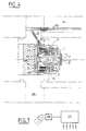
- Figure 1 is an axial sectional view of a first embodiment of the damper according to the invention and its control system, this view also showing schematically and partially the environment of the damper in the corresponding suspension element.
- Figure 2 is an axial sectional view on an enlarged scale of the damper of Figure 1.
- Figure 3 is a sectional view along 3-3 of the damper of Figures 1 and 2.
- FIGS. 4, 5 and 6 are views similar to FIGS. 1, 2 and 3, respectively illustrating a second embodiment of the shock absorber according to the invention, FIG. 6 being a section along line 6-6 of FIG. 5.
- FIG. 7 is a diagram showing the principle of an automatic damper control system also targeted by the invention.
- the damper shown in Figures 1 to 3 is intended to equip a hydropneumatic suspension element of a vehicle, in particular of a heavy vehicle, such as for example that described in patent application EP-A-274 935.
- This damper 1 comprises a fixed body constituted in this embodiment in two separate parts 1A and 1B, of revolution about an axis XX, and pierced with axial openings traversed by a tube 2 to which the two parts 1A, 1B of the body 1 are fixed.
- Each part 1A and 1B is pierced with holes 3,4 for the passage of the hydraulic fluid, distributed annularly.
- the openings 3 open into recesses 5 on the corresponding face of the part 1A and 1B, while the openings 4 are bores of tubular inserts 6 housed in the body and one end of which protrudes from the corresponding face of the parts 1A and 1B.
- the lights 3 and 4 are distributed in an alternate arrangement so that the lights 3 of the part there correspond the lights 4 of the part 1B and vice versa.
- the damper 1 comprises stacks 7 of elastically flexible metal washers, traversed by the central tube 2 and arranged in annular deflectors rigid 8 placed on each side of the body 1A, 1B opposite these openings 3 and 4.
- the deflectors 8 are resiliently held by the stacks 7 bearing against the projecting ends of the inserts 6 as long as the hydraulic pressure in the openings 4 is insufficient to separate them from these inserts 6, while the hydraulic fluid can freely pass between the same deflectors 8 and the ports 3 due to the spacing between the deflectors 8 and the recesses 5.
- the damper 1 comprises a disc 9 pierced with two series of holes 11, 12 distributed over a circle of axis XX and of different diameters. These holes are grouped in pairs opposite the openings 3,4, with between the two holes 11,12 of each pair a spacing e less than the diameter of the openings 3,4 of the body 1A, 1B.
- the damper includes means for making rotate the disc 9 by a determined angle equal to the angular sector between the centers of two consecutive holes 11,12. This allows one or the other of the series of holes 11 and 12 to be placed opposite the openings 3, 4 to vary the degree of damping.
- these means comprise the tube 2, at one end of which is fixed a washer 13 as well as a bottom 14, a bar 15 located in the center of the disc 9 and in its plane, integral with the latter by its ends , which pass through openings 16 of the tube 2 as well as elongated buttonholes 17 formed in a tubular sleeve 18 mounted sliding axially in the tube 2.
- the buttonholes 17 are inclined on the axis XX and the sleeve 18 can slide in the tube 2 to against the opposing force of an elastic return means constituted here by a helical spring 10 placed in abutment between the bottom 14.
- the sleeve 18 is locked in rotation relative to the tube 2 by any suitable means, such as a pin 19 partially engaged in the internal wall of the tube 2 and the projecting part of which is received in a longitudinal groove 21 of the sleeve 18.
- the damper is equipped with means for controlling the rotating disc 9, which in this embodiment comprises an electromagnet 22 mounted on a support 23 formed by a cup fixed to the end of the tube 2 opposite its cap 14.
- the electromagnet 22 is associated with an iron 24 secured to the end of the sleeve 18 opposite the spring 10.
- the iron 24 is placed in the electromagnet 22 so as to drive the sleeve 18 in axial translation against the restoring force of the spring 10 when the electromagnet 22 is excited by electrical connections 25,26 (Fig. 1) appropriate.
- the spring 10 maintains the sleeve 18 and the iron 24 in their rest position of FIG. 2, in which one of the two series of holes 11,12 opens into the lights 3 and 4.
- the electric wires 25, 26 pass through a socket 44 and a passage 27 formed in a capacitor 28, and are embedded in glass flowing in the passage 27 so as to completely block it and to be able to withstand extremely high pressures (possibly of around 1000 bars) inside the shock absorber 1. Beyond the passage 27, the electrical wires 25, 26 extend in another conduit 29 inside a casing 31.
- the damper control circuit is completed by a manual handle 32 and possibly by a time delay 33 connected to the connections 25, 26.
- the suspension element comprises a piston 34 and can be of any type, for example those described in the patent applications of the applicant EP-A- 0 197 859, EP-A- 0274 935 and EP-A- 0 307 263.
- At least one axial buttonhole 30 is formed in the tube 2 and is traversed by a lug 20 fixed to the sleeve 18 and capable of sliding therein.
- the ends of the buttonhole 30 form stops for the sliding movements of the sleeve 18.
- the electromagnet 22 is de-energized, the spring 10 is relaxed and maintains the sleeve 18 in the position of FIG. 2 where it is retained in abutment.
- the disc 9 is in an angular position such that the holes 11 of larger diameter are in correspondence with the lights 3 and 4.
- the holes 11 of large diameter are used for the normal running of the vehicle, to which they provide a relatively flexible suspension.
- the control handle 32 is actuated in order to excite the electromagnet 22.
- the iron 24 moves axially and drives the sleeve 18 until the bevelled edge 24a of the iron 24 abuts against a corresponding surface 23a of the support 23.
- the bar 15 drives the disc 9 in rotation due to the axial movement of the buttonholes 17.
- the holes 12 of small diameter are placed opposite lights 3 and 4.
- the disc 9 returns to its initial position after the excitation of the electromagnet 22 has ceased, thanks to the return spring 10.
- timer 33 can be provided to automatically put the shock absorber in the "hard” position (that is to say that where the holes of small diameter 12 are used), in particular for the automatic preparation for shooting. 'an armored vehicle.
- the second embodiment of the shock absorber shown in FIGS. 4 to 6 differs from the previous one in that the disc 9 is annularly pierced with three series of holes 35, 36, 37 of different diameters and grouped by three, and it is correspondingly provided two electromagnets 38, 39 for controlling the disc 9.
- the smallest holes 36 correspond to a hard suspension
- the holes 37, of larger diameter correspond to a flexible suspension
- the holes 35, of intermediate diameter correspond to a normal suspension, in which the spring 10 is relaxed and the electromagnets 38,39 de-energized.
- These are connected to three wires 41,42,43 passing through an electrical outlet 44 according to an arrangement similar to that of the previous embodiment.
- the electromagnets 38, 39 are mounted coaxially on a support 45 integral with the end of the tube 2 opposite the bottom 14. With the external electromagnet 38 is associated an iron 46 in the form of a cup in which a notch is formed. 47 thread passage 41,42,43. Under the iron 46 is disposed a second annular iron 48 of smaller diameter, which can slide inside the electromagnet 39.
- Each iron 46, 48 is provided with a respective flange 46a, 48a, the end is bevelled so as to be able to come into abutment against a corresponding surface 45a, 45b of the support 45.
- the irons 46, 48 and the inclined surfaces 45a, 45b are arranged so that the iron 46 can slide axially with the sleeve 18 over a distance d1 when only the electromagnet 38 is excited, also driving the iron 48 in this movement.
- the second electromagnet 39 When the second electromagnet 39 is also excited, it again drives the iron 48 and the sleeve 18 until the bevelled end of the flange 48a comes into abutment on the surface 45b, after having traveled a total distance d2 greater than d1.
- the spring 10 At rest, the spring 10 is relaxed and the sleeve 18 and the irons 46,48 are in the position of FIG. 5, the electromagnets 38,39 not being excited.
- the holes 35 corresponding to normal rolling are placed opposite the slots 3 and 4.
- the bar 15 is at the bottom of the buttonholes 17 and the lug 20 held in abutment against one end of the buttonhole 30.
- the return spring 10 returns the disc 9 and the sleeve 18 to their initial position.
- the positions can be mixed discs 9 of the shock absorbers associated with the various suspension elements.
- the suspension elements placed in the center of the vehicle can be put in the "hard” position, while the shock absorbers of the suspension elements placed at the ends can be put in the flexible position, or vice versa to damp the pitch on undulating ground.
Landscapes
- Engineering & Computer Science (AREA)
- General Engineering & Computer Science (AREA)
- Mechanical Engineering (AREA)
- Vehicle Body Suspensions (AREA)
- Fluid-Damping Devices (AREA)
Claims (7)
Applications Claiming Priority (2)
| Application Number | Priority Date | Filing Date | Title |
|---|---|---|---|
| FR8802426 | 1988-02-26 | ||
| FR8802426A FR2627829B1 (fr) | 1988-02-26 | 1988-02-26 | Dispositif amortisseur pour element de suspension hydropneumatique de vehicule, et amortisseur faisant partie de ce dispositif |
Publications (2)
| Publication Number | Publication Date |
|---|---|
| EP0330535A1 EP0330535A1 (de) | 1989-08-30 |
| EP0330535B1 true EP0330535B1 (de) | 1992-04-22 |
Family
ID=9363697
Family Applications (1)
| Application Number | Title | Priority Date | Filing Date |
|---|---|---|---|
| EP89400286A Expired - Lifetime EP0330535B1 (de) | 1988-02-26 | 1989-02-01 | Dämpfer für ein hydropneumatisches Fahrzeugaufhängungselement, insbesondere für Schwerfahrzeuge |
Country Status (6)
| Country | Link |
|---|---|
| US (1) | US4964492A (de) |
| EP (1) | EP0330535B1 (de) |
| JP (1) | JPH01255731A (de) |
| DE (1) | DE68901279D1 (de) |
| ES (1) | ES2030980T3 (de) |
| FR (1) | FR2627829B1 (de) |
Families Citing this family (12)
| Publication number | Priority date | Publication date | Assignee | Title |
|---|---|---|---|---|
| DE3937795A1 (de) * | 1989-05-26 | 1990-11-29 | Bosch Gmbh Robert | Stossdaempfer |
| DE3921239C1 (de) * | 1989-06-29 | 1991-02-07 | August Bilstein Gmbh & Co Kg, 5828 Ennepetal, De | |
| DE3922891A1 (de) * | 1989-07-12 | 1991-01-17 | Bosch Gmbh Robert | Hydraulischer, regelbarer stossdaempfer |
| US20050051397A1 (en) * | 2003-09-04 | 2005-03-10 | Brian Goscinski | Remote adjustable shock absorber |
| US7252181B2 (en) * | 2003-12-17 | 2007-08-07 | Tenneco Automotive Operating Company Inc. | Air pressure proportional damper |
| US7562750B2 (en) * | 2004-02-10 | 2009-07-21 | Tenneco Automotive Operating Company Inc. | Air pressure proportional damper for shock absorber |
| GB0703021D0 (de) * | 2007-02-16 | 2007-03-28 | Specialised Petroleum Serv Ltd | |
| DE102014211939B4 (de) * | 2014-06-23 | 2025-05-08 | Ford Global Technologies, Llc | Schwingungsdämpfer, insbesondere dämpfungseinstellbarer Stoßdämpfer für Kraftfahrzeuge |
| CN115539554B (zh) * | 2022-09-20 | 2025-03-25 | 重庆交通大学 | 带限位装置的阻尼调节阀 |
| CN115574037B (zh) * | 2022-09-28 | 2024-10-18 | 重庆交通大学 | 阻尼连续可调减振器 |
| CN118622906A (zh) * | 2023-03-10 | 2024-09-10 | 英业达科技有限公司 | 移动载具及减震组件 |
| DE102023125837A1 (de) * | 2023-09-25 | 2025-03-27 | Thyssenkrupp Ag | Dämpferventil und Schwingungsdämpfer |
Family Cites Families (25)
| Publication number | Priority date | Publication date | Assignee | Title |
|---|---|---|---|---|
| BE389381A (de) * | 1932-06-08 | |||
| US3548977A (en) * | 1966-11-09 | 1970-12-22 | Frank S Morgan | Shock absorbers |
| US3559776A (en) * | 1969-06-17 | 1971-02-02 | Gen Motors Corp | Shock lockout and piston system |
| US4061295A (en) * | 1975-12-22 | 1977-12-06 | The Boeing Company | Shock absorbing method and apparatus |
| JPS5442570A (en) * | 1977-08-12 | 1979-04-04 | Honda Motor Co Ltd | Hydraulic buffer for vehicle |
| DE3231739A1 (de) * | 1982-08-26 | 1984-03-01 | Fichtel & Sachs Ag, 8720 Schweinfurt | Zweirohr-schwingungsdaempfer oder federbein mit veraenderbarer daempfkraft |
| US4513833A (en) * | 1983-04-06 | 1985-04-30 | Sheldon Daniel F | Controlled vehicle damping |
| GB2147683B (en) * | 1983-09-24 | 1986-10-01 | Bilstein August Gmbh Co Kg | Shock absorber, with electromagnetically biased pressure responsive valve |
| JPS60151440A (ja) * | 1984-01-13 | 1985-08-09 | Kayaba Ind Co Ltd | 油圧緩衝器 |
| US4620620A (en) * | 1984-03-12 | 1986-11-04 | General Motors Corporation | Actuator for adjustable hydraulic damper |
| JPH07102766B2 (ja) * | 1984-09-20 | 1995-11-08 | トキコ株式会社 | 車両懸架装置 |
| DE3446133A1 (de) * | 1984-12-18 | 1986-06-19 | Fichtel & Sachs Ag, 8720 Schweinfurt | Schwingungsdaempfer mit veraenderbarer daempfkraft |
| US4685545A (en) * | 1984-12-24 | 1987-08-11 | General Motors Corporation | Hydraulic damper for vehicles with variable orifice piston valving for varying damping force |
| DE3584151D1 (de) * | 1984-12-27 | 1991-10-24 | Nippon Denso Co | Elektromagnetisches stroemungsregelungsventil. |
| FR2579935B1 (de) * | 1985-04-03 | 1989-06-02 | Applic Mach Motrices | |
| FR2583125B1 (fr) * | 1985-06-10 | 1987-12-24 | Applic Mach Motrices | Amortisseur pour element de suspension de vehicule lourd |
| DE3523628A1 (de) * | 1985-07-02 | 1987-01-15 | Bayerische Motoren Werke Ag | Ventilsystem fuer steuerbare, hydraulische schwingungsdaempfer |
| FR2585795B3 (fr) * | 1985-07-30 | 1987-09-11 | Renault | Dispositif de commande electrohydraulique continue de la force d'amortissement dans un amortisseur |
| JPS6267342A (ja) * | 1985-09-19 | 1987-03-27 | Aisin Seiki Co Ltd | 回転角度制御用ロ−タリ−アクチユエ−タ |
| FR2597952B1 (fr) * | 1986-04-29 | 1990-11-09 | Applic Mach Motrices | Clapet d'ecretage a ouverture rapide pour element de suspension hydropneumatique de vehicule lourd |
| FR2606109B1 (fr) * | 1986-10-31 | 1992-12-04 | Atsugi Motor Parts Co Ltd | Dispositif rotatif de manoeuvre et amortisseur a action variable |
| DE3644447A1 (de) * | 1986-12-24 | 1988-07-07 | Bosch Gmbh Robert | Vorrichtung zur daempfung von bewegungsablaeufen |
| FR2609131B1 (fr) * | 1986-12-26 | 1989-12-08 | Applic Mach Motrices | Amortisseur pour element de suspension hydropneumatique de vehicule et dispositif incorporant cet amortisseur et un clapet d'ecretage double sens a ouverture rapide |
| US4821851A (en) * | 1987-08-21 | 1989-04-18 | General Motors Corporation | Damper with optimized adjustable valving for vehicle ride control |
| FR2620385B1 (fr) * | 1987-09-10 | 1992-07-24 | Applic Mach Motrices | Element de suspension hydropneumatique pour vehicule a roues, notamment tout terrain |
-
1988
- 1988-02-26 FR FR8802426A patent/FR2627829B1/fr not_active Expired - Lifetime
-
1989
- 1989-02-01 ES ES198989400286T patent/ES2030980T3/es not_active Expired - Lifetime
- 1989-02-01 DE DE8989400286T patent/DE68901279D1/de not_active Expired - Lifetime
- 1989-02-01 EP EP89400286A patent/EP0330535B1/de not_active Expired - Lifetime
- 1989-02-24 US US07/314,859 patent/US4964492A/en not_active Expired - Fee Related
- 1989-02-27 JP JP1046362A patent/JPH01255731A/ja active Pending
Also Published As
| Publication number | Publication date |
|---|---|
| FR2627829B1 (fr) | 1990-08-10 |
| ES2030980T3 (es) | 1992-11-16 |
| DE68901279D1 (de) | 1992-05-27 |
| EP0330535A1 (de) | 1989-08-30 |
| FR2627829A1 (fr) | 1989-09-01 |
| JPH01255731A (ja) | 1989-10-12 |
| US4964492A (en) | 1990-10-23 |
Similar Documents
| Publication | Publication Date | Title |
|---|---|---|
| EP0330535B1 (de) | Dämpfer für ein hydropneumatisches Fahrzeugaufhängungselement, insbesondere für Schwerfahrzeuge | |
| EP0133398B1 (de) | Mehrstufige hydraulische Energiezerstreuungsanlage | |
| EP1638792B1 (de) | Verbesserte anhängerkupplungsanordnung, die die schlingerbewegungen eines von einem kraftfahrzeug gezogenen strassenanhängers dämpft | |
| EP0236196A1 (de) | Aufhängungs- und Lenkungsvorrichtung für Motorrad | |
| BE1011266A3 (fr) | Carottier. | |
| FR2594782A2 (fr) | Dispositif de suspension et de commande de direction pour motocycle | |
| FR2609945A1 (fr) | Dispositif de suspension et de pivotement d'une roue directrice de vehicule automobile | |
| CA1225072A (fr) | Atterrisseur de type a balancier | |
| EP0554147A1 (de) | Aufhängungseinheit für ein schweres Fahrzeug, insbesondere für ein Gleiskettenfahrzeug | |
| EP0489638B1 (de) | Aufhängungsvorrichtung, insbesondere für gelenktes Rad eines Kraftfahrzeugs | |
| FR2514316A1 (fr) | Systeme de suspension arriere de motocyclettes equipe d'un mecanisme d'articulation progressive | |
| EP0222678A1 (de) | Fahrzeug mit Mörseraufbau | |
| FR2813847A1 (fr) | Systeme de montage d'un garde-boue equipant une roue directrice d'un vehicule | |
| EP0197859B1 (de) | Aufhängungsvorrichtung für schweres Fahrzeug | |
| EP0933552B1 (de) | Mechanische Einrichtung mit zwei Betriebsarten | |
| CA1203711A (fr) | Mecanisme a barillet pour une pompe a piston | |
| EP0430746B1 (de) | Abstützvorrichtung, insbesondere für die Achse einer Hinterradaufhängung an der Karosserie eines Kraftfahrzeuges | |
| EP0493152B1 (de) | Automatisches Steuergerät für eine hydraulische Niveaureguliereinrichtung einer Hinterachsaufhängung eines Kraftfahrzeug und damit ausgerüstete Mischaufhängung | |
| FR2586619A1 (fr) | Perfectionnements aux trains orientables de vehicules dont l'orientation est commandee par deplacement du centre de gravite | |
| EP0712743B1 (de) | Antirollvorrichtung für Kraftfahrzeugachse | |
| FR2536019A1 (fr) | Dispositif de correction d'assiette pour vehicule automobile | |
| EP0021950B1 (de) | Servolenkung für Kraftfahrzeug | |
| FR2701314A1 (fr) | Variation de la vitesse de rotation de corps tournants. | |
| FR2758434A1 (fr) | Dispositif de suspension pour rampe de pulverisation agricole | |
| EP0165887B1 (de) | Bodenwalze und Landmaschine mit einer solchen Walze |
Legal Events
| Date | Code | Title | Description |
|---|---|---|---|
| PUAI | Public reference made under article 153(3) epc to a published international application that has entered the european phase |
Free format text: ORIGINAL CODE: 0009012 |
|
| AK | Designated contracting states |
Kind code of ref document: A1 Designated state(s): CH DE ES GB IT LI |
|
| 17P | Request for examination filed |
Effective date: 19891009 |
|
| 17Q | First examination report despatched |
Effective date: 19910128 |
|
| GRAA | (expected) grant |
Free format text: ORIGINAL CODE: 0009210 |
|
| AK | Designated contracting states |
Kind code of ref document: B1 Designated state(s): CH DE ES GB IT LI |
|
| ITF | It: translation for a ep patent filed | ||
| REF | Corresponds to: |
Ref document number: 68901279 Country of ref document: DE Date of ref document: 19920527 |
|
| GBT | Gb: translation of ep patent filed (gb section 77(6)(a)/1977) | ||
| REG | Reference to a national code |
Ref country code: ES Ref legal event code: FG2A Ref document number: 2030980 Country of ref document: ES Kind code of ref document: T3 |
|
| PLBE | No opposition filed within time limit |
Free format text: ORIGINAL CODE: 0009261 |
|
| STAA | Information on the status of an ep patent application or granted ep patent |
Free format text: STATUS: NO OPPOSITION FILED WITHIN TIME LIMIT |
|
| 26N | No opposition filed | ||
| PGFP | Annual fee paid to national office [announced via postgrant information from national office to epo] |
Ref country code: GB Payment date: 19950228 Year of fee payment: 7 Ref country code: ES Payment date: 19950228 Year of fee payment: 7 |
|
| PGFP | Annual fee paid to national office [announced via postgrant information from national office to epo] |
Ref country code: CH Payment date: 19950320 Year of fee payment: 7 |
|
| PGFP | Annual fee paid to national office [announced via postgrant information from national office to epo] |
Ref country code: DE Payment date: 19950321 Year of fee payment: 7 |
|
| PG25 | Lapsed in a contracting state [announced via postgrant information from national office to epo] |
Ref country code: GB Effective date: 19960201 |
|
| PG25 | Lapsed in a contracting state [announced via postgrant information from national office to epo] |
Ref country code: ES Free format text: LAPSE BECAUSE OF NON-PAYMENT OF DUE FEES Effective date: 19960202 |
|
| PG25 | Lapsed in a contracting state [announced via postgrant information from national office to epo] |
Ref country code: LI Free format text: LAPSE BECAUSE OF NON-PAYMENT OF DUE FEES Effective date: 19960228 Ref country code: CH Free format text: LAPSE BECAUSE OF NON-PAYMENT OF DUE FEES Effective date: 19960228 |
|
| GBPC | Gb: european patent ceased through non-payment of renewal fee |
Effective date: 19960201 |
|
| REG | Reference to a national code |
Ref country code: CH Ref legal event code: PL |
|
| PG25 | Lapsed in a contracting state [announced via postgrant information from national office to epo] |
Ref country code: DE Effective date: 19961101 |
|
| REG | Reference to a national code |
Ref country code: ES Ref legal event code: FD2A Effective date: 19990503 |
|
| PG25 | Lapsed in a contracting state [announced via postgrant information from national office to epo] |
Ref country code: IT Free format text: LAPSE BECAUSE OF NON-PAYMENT OF DUE FEES;WARNING: LAPSES OF ITALIAN PATENTS WITH EFFECTIVE DATE BEFORE 2007 MAY HAVE OCCURRED AT ANY TIME BEFORE 2007. THE CORRECT EFFECTIVE DATE MAY BE DIFFERENT FROM THE ONE RECORDED. Effective date: 20050201 |