EP0331432A2 - A suction cleaner - Google Patents
A suction cleaner Download PDFInfo
- Publication number
- EP0331432A2 EP0331432A2 EP89301980A EP89301980A EP0331432A2 EP 0331432 A2 EP0331432 A2 EP 0331432A2 EP 89301980 A EP89301980 A EP 89301980A EP 89301980 A EP89301980 A EP 89301980A EP 0331432 A2 EP0331432 A2 EP 0331432A2
- Authority
- EP
- European Patent Office
- Prior art keywords
- suction
- chamber
- blade
- dust chamber
- refuse
- Prior art date
- Legal status (The legal status is an assumption and is not a legal conclusion. Google has not performed a legal analysis and makes no representation as to the accuracy of the status listed.)
- Granted
Links
- 239000000428 dust Substances 0.000 claims abstract description 25
- 238000007599 discharging Methods 0.000 claims 1
- 230000000717 retained effect Effects 0.000 claims 1
- 238000010276 construction Methods 0.000 description 1
- 230000005611 electricity Effects 0.000 description 1
- 230000004048 modification Effects 0.000 description 1
- 238000012986 modification Methods 0.000 description 1
- 239000004575 stone Substances 0.000 description 1
Images


Classifications
-
- A—HUMAN NECESSITIES
- A47—FURNITURE; DOMESTIC ARTICLES OR APPLIANCES; COFFEE MILLS; SPICE MILLS; SUCTION CLEANERS IN GENERAL
- A47L—DOMESTIC WASHING OR CLEANING; SUCTION CLEANERS IN GENERAL
- A47L5/00—Structural features of suction cleaners
- A47L5/12—Structural features of suction cleaners with power-driven air-pumps or air-compressors, e.g. driven by motor vehicle engine vacuum
- A47L5/22—Structural features of suction cleaners with power-driven air-pumps or air-compressors, e.g. driven by motor vehicle engine vacuum with rotary fans
-
- A—HUMAN NECESSITIES
- A01—AGRICULTURE; FORESTRY; ANIMAL HUSBANDRY; HUNTING; TRAPPING; FISHING
- A01G—HORTICULTURE; CULTIVATION OF VEGETABLES, FLOWERS, RICE, FRUIT, VINES, HOPS OR SEAWEED; FORESTRY; WATERING
- A01G20/00—Cultivation of turf, lawn or the like; Apparatus or methods therefor
- A01G20/40—Apparatus for cleaning the lawn or grass surface
- A01G20/43—Apparatus for cleaning the lawn or grass surface for sweeping, collecting or disintegrating lawn debris
- A01G20/47—Vacuum or blower devices
-
- A—HUMAN NECESSITIES
- A47—FURNITURE; DOMESTIC ARTICLES OR APPLIANCES; COFFEE MILLS; SPICE MILLS; SUCTION CLEANERS IN GENERAL
- A47L—DOMESTIC WASHING OR CLEANING; SUCTION CLEANERS IN GENERAL
- A47L9/00—Details or accessories of suction cleaners, e.g. mechanical means for controlling the suction or for effecting pulsating action; Storing devices specially adapted to suction cleaners or parts thereof; Carrying-vehicles specially adapted for suction cleaners
- A47L9/02—Nozzles
-
- E—FIXED CONSTRUCTIONS
- E01—CONSTRUCTION OF ROADS, RAILWAYS, OR BRIDGES
- E01H—STREET CLEANING; CLEANING OF PERMANENT WAYS; CLEANING BEACHES; DISPERSING OR PREVENTING FOG IN GENERAL CLEANING STREET OR RAILWAY FURNITURE OR TUNNEL WALLS
- E01H1/00—Removing undesirable matter from roads or like surfaces, with or without moistening of the surface
- E01H1/08—Pneumatically dislodging or taking-up undesirable matter or small objects; Drying by heat only or by streams of gas; Cleaning by projecting abrasive particles
- E01H1/0827—Dislodging by suction; Mechanical dislodging-cleaning apparatus with independent or dependent exhaust, e.g. dislodging-sweeping machines with independent suction nozzles ; Mechanical loosening devices working under vacuum
- E01H1/0836—Apparatus dislodging all of the dirt by suction ; Suction nozzles
Definitions
- the present invention relates to a suction cleaner for collecting relatively large refuse on roads and gardens, such as dead leaves and branches.
- Portable suction cleaners which comprise a suction duct in a front section and a power vacuum pump in a rear section.
- the suction duct has a simple hollow construction, so that it is often choked with relatively large refuse such as twigs or rubbish lumps.
- One object of the present invention is to avoid such choking and to provide a suction cleaner capable of shredding the sucked refuse to pieces.
- a suction cleaner comprising a duct chamber into which, in use, refuse is drawn by suction, agitator means mounted for movement within the dust chamber, and at least one blade arranged for co-operation with the agitator means to shred refuse and to be retractable to an inoperative position.
- the cleaner comprises suction chamber and a dust chamber communicating with the suction chamber.
- the dust chamber including a plurality of edged agitators having first blades, to which a second blade is presented so as to shred the refuse to small pieces, the second blade being retractable from an operative position to an inoperative position in which the second blade is remote from the first blades.
- the suction cleaner of the invention has a dust chamber 1 and an outlet duct 2 tangentially connected to the dust chamber 1 (refer to Figure 5).
- the dust chamber 1 has an open top end which is covered by a cylindrical suction chamber 3, wherein a ring-shaped flange 3a thereof is fixed to the periphery of the open top end of the dust chamber 1.
- an agitator in the form of a rotor having radially extending vanes 5 and fixed to a driving shaft 4 projecting into the dust chamber 1.
- Each vane 5 has an outer side and an inner side, which is formed into a blade 5a as best shown in Figure 1.
- these blades 5a will be referred to as rotary blades, as opposed to a stationary blade 6a, which will be described below.
- the stationary blade 6a is formed on the lower end portion of a shank 6 adjacent the inner side of the rotary vanes 5.
- the shank 6 is normally located in an operative position at which, as shown in Figure 1, the stationary blade 6a is presented to the rotary blades 5a leaving therebetween a gap (G) sufficient to enable both blades 5a and 6a to shred the refuse therebetween.
- the shank 6 has a protuberance 6b and a ledge 6c supporting a coil spring 11.
- the suction chamber 3 has a window 3b is which the shank 6 is movable provided.
- the window 3b is covered with an inner cover 7 and the shank 6 is covered with an outer cover 7 (as best shown in Figure 4) both being fixed to the dust chamber 3 with the shank 6 located between them.
- the outer cover 8 has a vertically extending slot 8a in which the ledge 6c is movable inserted and a horizontally extending slit 8b slightly below the vertical slot 8a in which the protuberance 6b is releasably inserted.
- the ledge 6c passes through a holder 9 for one end of a spring 10 the other end of which is fixed to an upper portion of the outer cover 8. In this way the ledge 6c is upwardly biased by the spring 10.
- the spring 11 on the ledge 6c is supported against the spring holder 9. If anything is caught in the blades 5a and 6a, the stationary blade 6a is forced away from the rotary blades 5a against the spring 11 to disengage the protuberance 6b from the slit 8b. As a result, the shank 6 is withdrawn upwardly from the operative position to the position shown by phantom lines in Figure 1. Thus, the blades 5a and 6a are protected against breakage.
- FIGS 5 to 7 show a modified version of the suction cleaner in which the dust chamber 3 is connected to the suction chamber 1 at its bottom.
- the outlet duct 2 is likewise tangentially connected to the suction chamber 1.
- the rotor vanes 5 having blades 5a are radially fixed to a driving shaft 12a of a motor 12 mounted on top of the suction chamber 1.
- the vanes 5 are curved in the direction of rotation.
- There is provided an L-shaped shank 13 having a short leg 13c and a blade 13a, a ledge 13d supporting the spring 11, and a bent tail portion 13c having a round hole 13b.
- the ledge 13d and the short leg 13c respectively pass through apertures 3d and 3c formed in a wall of the dust chamber 3.
- the short leg 13c has a round hole 13b through which a flanged pin 15 passes as shown in Figure 5.
- Flanges 14 serves to retain the pin 15 in the hole 13b.
- the ledge 13d supports a spring 11 against the wall of the dust chamber 3.
- the shank 13 is disposed in an operative position as shown in Figure 6 with an adequate gap between the two blades 5a and 13a.
- the shank 13 is angularly displaced as shown in Figure 7 so that the stationary blade 13a is forced away from the rotary blades 5a. In this way the blades 5a and 13a are protected against breakage.
- the cleaner When the cleaner is switched on, the motor is driven, thereby sucking refuse on a road into the dust chamber through the suction chamber. The refuse is cut to pieces by and between the rotary blades and the stationary blades. Small pieces of refuse are then discharged through the outlet duct 2, which is normally fitted with a storage bag.
- the cleaner may include a battery, thereby making it portable for use in the absence of any other source of electricity.
Landscapes
- Engineering & Computer Science (AREA)
- Life Sciences & Earth Sciences (AREA)
- Environmental Sciences (AREA)
- Architecture (AREA)
- Civil Engineering (AREA)
- Structural Engineering (AREA)
- Mechanical Engineering (AREA)
- Nozzles For Electric Vacuum Cleaners (AREA)
- Cleaning Of Streets, Tracks, Or Beaches (AREA)
Abstract
Description
- The present invention relates to a suction cleaner for collecting relatively large refuse on roads and gardens, such as dead leaves and branches.
- Portable suction cleaners are known which comprise a suction duct in a front section and a power vacuum pump in a rear section. The suction duct has a simple hollow construction, so that it is often choked with relatively large refuse such as twigs or rubbish lumps.
- One object of the present invention is to avoid such choking and to provide a suction cleaner capable of shredding the sucked refuse to pieces.
- According to the present invention we propose a suction cleaner comprising a duct chamber into which, in use, refuse is drawn by suction, agitator means mounted for movement within the dust chamber, and at least one blade arranged for co-operation with the agitator means to shred refuse and to be retractable to an inoperative position.
- In a preferred embodiment the cleaner comprises suction chamber and a dust chamber communicating with the suction chamber. The dust chamber including a plurality of edged agitators having first blades, to which a second blade is presented so as to shred the refuse to small pieces, the second blade being retractable from an operative position to an inoperative position in which the second blade is remote from the first blades.
- Other objects and advantages of the present invention will become apparent from the following detailed description by way of example, of preferred embodiments. Reference is made to the accompanying drawings in which:
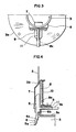
- Figure 1 is a vertical cross-section through part of a suction cleaner;
- Figure 2 is a view from the right in Figure 1;
- Figure 3 is a plan view of a part of the suction cleaner of Figure 1;
- Figure 4 shows in cross-section details of a modification to the cleaner of Figure 1;
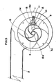
- Figure 5 is a plan view showing a modified cleaner;
- Figure 6 is a front view of the cleaner of Figure 5; and
- Figure 7 is a fragmentary cross-section showing a small object caught between a rotary blade and a stationary blade, in the embodiment of Figures 5 and 6.
- Referring to Figures 1 to 4 the suction cleaner of the invention has a dust chamber 1 and an
outlet duct 2 tangentially connected to the dust chamber 1 (refer to Figure 5). The dust chamber 1 has an open top end which is covered by acylindrical suction chamber 3, wherein a ring-shaped flange 3a thereof is fixed to the periphery of the open top end of the dust chamber 1. Within the dust chamber 1 is an agitator in the form of a rotor having radially extendingvanes 5 and fixed to adriving shaft 4 projecting into the dust chamber 1. Eachvane 5 has an outer side and an inner side, which is formed into ablade 5a as best shown in Figure 1. Hereinafter theseblades 5a will be referred to as rotary blades, as opposed to astationary blade 6a, which will be described below. - The
stationary blade 6a is formed on the lower end portion of ashank 6 adjacent the inner side of therotary vanes 5. Theshank 6 is normally located in an operative position at which, as shown in Figure 1, thestationary blade 6a is presented to therotary blades 5a leaving therebetween a gap (G) sufficient to enable bothblades shank 6 has aprotuberance 6b and a ledge 6c supporting acoil spring 11. Thesuction chamber 3 has awindow 3b is which theshank 6 is movable provided. Thewindow 3b is covered with aninner cover 7 and theshank 6 is covered with an outer cover 7 (as best shown in Figure 4) both being fixed to thedust chamber 3 with theshank 6 located between them. Theouter cover 8 has a vertically extendingslot 8a in which theledge 6c is movable inserted and a horizontally extendingslit 8b slightly below thevertical slot 8a in which theprotuberance 6b is releasably inserted. The ledge 6c passes through aholder 9 for one end of aspring 10 the other end of which is fixed to an upper portion of theouter cover 8. In this way the ledge 6c is upwardly biased by thespring 10. Thespring 11 on the ledge 6c is supported against thespring holder 9. If anything is caught in theblades stationary blade 6a is forced away from therotary blades 5a against thespring 11 to disengage theprotuberance 6b from theslit 8b. As a result, theshank 6 is withdrawn upwardly from the operative position to the position shown by phantom lines in Figure 1. Thus, theblades - Figures 5 to 7 show a modified version of the suction cleaner in which the
dust chamber 3 is connected to the suction chamber 1 at its bottom. Theoutlet duct 2 is likewise tangentially connected to the suction chamber 1. Therotor vanes 5 havingblades 5a are radially fixed to a driving shaft 12a of amotor 12 mounted on top of the suction chamber 1. Thevanes 5 are curved in the direction of rotation. There is provided an L-shaped shank 13 having ashort leg 13c and ablade 13a, a ledge 13d supporting thespring 11, and abent tail portion 13c having around hole 13b. The ledge 13d and theshort leg 13c respectively pass throughapertures dust chamber 3. Theshort leg 13c has around hole 13b through which aflanged pin 15 passes as shown in Figure 5.Flanges 14 serves to retain thepin 15 in thehole 13b. The ledge 13d supports aspring 11 against the wall of thedust chamber 3. Normally theshank 13 is disposed in an operative position as shown in Figure 6 with an adequate gap between the twoblades shank 13 is angularly displaced as shown in Figure 7 so that thestationary blade 13a is forced away from therotary blades 5a. In this way theblades - When the cleaner is switched on, the motor is driven, thereby sucking refuse on a road into the dust chamber through the suction chamber. The refuse is cut to pieces by and between the rotary blades and the stationary blades. Small pieces of refuse are then discharged through the
outlet duct 2, which is normally fitted with a storage bag. The cleaner may include a battery, thereby making it portable for use in the absence of any other source of electricity.
Claims (7)
Priority Applications (1)
| Application Number | Priority Date | Filing Date | Title |
|---|---|---|---|
| DE1989617958 DE68917958T2 (en) | 1989-02-28 | 1989-02-28 | Vacuum cleaner. |
Applications Claiming Priority (1)
| Application Number | Priority Date | Filing Date | Title |
|---|---|---|---|
| JP63050152A JPH01223205A (en) | 1988-03-02 | 1988-03-02 | Suction type cleaner for cleaning fallen leaves |
Publications (3)
| Publication Number | Publication Date |
|---|---|
| EP0331432A2 true EP0331432A2 (en) | 1989-09-06 |
| EP0331432A3 EP0331432A3 (en) | 1991-03-27 |
| EP0331432B1 EP0331432B1 (en) | 1994-09-07 |
Family
ID=12851210
Family Applications (1)
| Application Number | Title | Priority Date | Filing Date |
|---|---|---|---|
| EP89301980A Expired - Lifetime EP0331432B1 (en) | 1988-03-02 | 1989-02-28 | A suction cleaner |
Country Status (3)
| Country | Link |
|---|---|
| US (1) | US4955107A (en) |
| EP (1) | EP0331432B1 (en) |
| JP (1) | JPH01223205A (en) |
Cited By (2)
| Publication number | Priority date | Publication date | Assignee | Title |
|---|---|---|---|---|
| US5452492A (en) * | 1992-09-26 | 1995-09-26 | Hamilton; Robin | Material collection |
| US5611268A (en) * | 1992-09-26 | 1997-03-18 | Hamilton; Robin | Compactor with expanding and contracting nozzle |
Families Citing this family (20)
| Publication number | Priority date | Publication date | Assignee | Title |
|---|---|---|---|---|
| GB2256128A (en) * | 1991-05-29 | 1992-12-02 | Francis John Caves | Vacuum cleaner garden accessory. |
| GB9406532D0 (en) * | 1994-03-31 | 1994-05-25 | Black & Decker Inc | Blower vacuum |
| GB2299749B (en) * | 1995-03-11 | 1998-09-02 | Black & Decker Inc | A blower vacuum device of improved design |
| US5588178A (en) * | 1995-06-07 | 1996-12-31 | Mcculloch Corporation | Impeller for blower/vacuum |
| US6170119B1 (en) * | 1999-06-01 | 2001-01-09 | Fantom Technologies Inc. | Method and apparatus for reducing the size of elongate particulate material in a vacuum cleaner head |
| USD461604S1 (en) | 2001-02-09 | 2002-08-13 | The Toro Company | Housing for a blower/vacuum |
| US6442790B1 (en) | 2001-02-09 | 2002-09-03 | The Toro Company | Portable blower/vacuum having air inlet cover attachable to blower tube |
| EP2258246B1 (en) * | 2006-09-22 | 2013-06-26 | Shop VAC Corporation | Mulcher |
| USD556395S1 (en) | 2006-12-22 | 2007-11-27 | The Toro Company | Housing for a convertible blower/vacuum |
| US7735188B2 (en) * | 2006-12-22 | 2010-06-15 | The Toro Company | Air inlet cover and portable blower/vacuum incorporating same |
| US20080152487A1 (en) * | 2006-12-22 | 2008-06-26 | Shaffer Chadwick A | Portable blower/vacuum and impeller for use with same |
| JP2009085015A (en) * | 2007-09-27 | 2009-04-23 | Kioritz Corp | Powered suction device |
| USD747050S1 (en) * | 2014-05-14 | 2016-01-05 | The Toro Company | Housing of a portable blower/vacuum |
| US11234568B2 (en) | 2016-09-09 | 2022-02-01 | Sharkninja Operating Llc | Agitator with hair removal |
| CN110494062B (en) | 2017-03-10 | 2022-01-25 | 尚科宁家运营有限公司 | Blender with remover and hair removal |
| CN113509076B (en) | 2017-05-26 | 2023-08-01 | 尚科宁家运营有限公司 | Hair cutting brush roller |
| CN111787836B (en) | 2017-12-27 | 2022-10-14 | 尚科宁家运营有限公司 | End cap assembly |
| US11672393B2 (en) | 2017-12-27 | 2023-06-13 | Sharkninja Operating Llc | Cleaning apparatus with selectable combing unit for removing debris from cleaning roller |
| CN110140521B (en) * | 2019-05-05 | 2024-04-05 | 沙雅钵施然智能农机有限公司 | Cotton picker wind power edulcoration system and cotton picker |
| CN115704403A (en) * | 2021-08-16 | 2023-02-17 | 南京泉峰科技有限公司 | Fan blower |
Family Cites Families (7)
| Publication number | Priority date | Publication date | Assignee | Title |
|---|---|---|---|---|
| US2733000A (en) * | 1956-01-31 | sparklin | ||
| US1527818A (en) * | 1924-11-07 | 1925-02-24 | Schutzo Neill Company | Grinding mill |
| US3790094A (en) * | 1972-03-22 | 1974-02-05 | J Spicer | Mobile leaf pulverizer |
| US4076460A (en) * | 1972-11-30 | 1978-02-28 | Roof Earl O | Convertible lawn care apparatus |
| US3968938A (en) * | 1974-09-10 | 1976-07-13 | Lambert Corporation | System for handling debris |
| DE3005701A1 (en) * | 1980-02-15 | 1981-08-20 | Rudolf 2000 Hamburg Schulze | Centrifugal suction blower for picking up leaves - has upstream rotary cutters to chop leaves before replacing on ground or in container |
| US4325163A (en) * | 1980-04-07 | 1982-04-20 | Allegretti & Company | Portable blower-vacuum unit |
-
1988
- 1988-03-02 JP JP63050152A patent/JPH01223205A/en active Granted
- 1988-07-22 US US07/222,748 patent/US4955107A/en not_active Expired - Lifetime
-
1989
- 1989-02-28 EP EP89301980A patent/EP0331432B1/en not_active Expired - Lifetime
Cited By (3)
| Publication number | Priority date | Publication date | Assignee | Title |
|---|---|---|---|---|
| US5452492A (en) * | 1992-09-26 | 1995-09-26 | Hamilton; Robin | Material collection |
| US5611268A (en) * | 1992-09-26 | 1997-03-18 | Hamilton; Robin | Compactor with expanding and contracting nozzle |
| US5768744A (en) * | 1992-09-26 | 1998-06-23 | Hamilton; Robin | Self-propelled waste collection vehicle |
Also Published As
| Publication number | Publication date |
|---|---|
| JPH0358604B2 (en) | 1991-09-06 |
| US4955107A (en) | 1990-09-11 |
| EP0331432B1 (en) | 1994-09-07 |
| EP0331432A3 (en) | 1991-03-27 |
| JPH01223205A (en) | 1989-09-06 |
Similar Documents
| Publication | Publication Date | Title |
|---|---|---|
| EP0331432B1 (en) | A suction cleaner | |
| CA2198524A1 (en) | Blowing and suction device, more specifically a vacuum device for picking up and shredding leaves and similar material | |
| US3968938A (en) | System for handling debris | |
| US5692262A (en) | Mulching impeller for lawn and garden mulching blower-vacuum | |
| US4129977A (en) | Low speed rotary mower | |
| US4083166A (en) | Mulcher attachment for rotary power mower | |
| US5245726A (en) | Apparatus for picking up and shredding natural yard waste | |
| US5669563A (en) | Chipper shredder with use-enhancing features | |
| US3940827A (en) | Leaf vacuuming attachment for rotary lawn mowers | |
| US5794864A (en) | Portable lawn and garden mulching vacuum | |
| USRE29139E (en) | Lawn maintenance equipment | |
| US5142851A (en) | Post-processing apparatus for lawn mowers and the like | |
| US3000165A (en) | Lawn mower | |
| EP1023864A3 (en) | Dust-collecting device for vacuum cleaner and upright type vacuum cleaner | |
| US3014330A (en) | Rotary power lawnmower | |
| US3593505A (en) | Mower motor cooling system | |
| US3797212A (en) | Combination mowing-mulching apparatus | |
| US5156345A (en) | Fan-type yard waste processing apparatus | |
| US5385308A (en) | Chipper-shredder | |
| US3884020A (en) | Leaf shredding means for rotary mowers | |
| US3049857A (en) | Comminutor | |
| US5107662A (en) | Mower | |
| US3974629A (en) | Lawn mower with improved mulching attachment | |
| US5603459A (en) | Chipper-shredder with enhanced user features | |
| US5875620A (en) | Lawnmower blower apparatus |
Legal Events
| Date | Code | Title | Description |
|---|---|---|---|
| PUAI | Public reference made under article 153(3) epc to a published international application that has entered the european phase |
Free format text: ORIGINAL CODE: 0009012 |
|
| AK | Designated contracting states |
Kind code of ref document: A2 Designated state(s): BE CH DE FR GB IT LI NL |
|
| PUAL | Search report despatched |
Free format text: ORIGINAL CODE: 0009013 |
|
| AK | Designated contracting states |
Kind code of ref document: A3 Designated state(s): BE CH DE FR GB IT LI NL |
|
| 17P | Request for examination filed |
Effective date: 19910923 |
|
| 17Q | First examination report despatched |
Effective date: 19930331 |
|
| GRAA | (expected) grant |
Free format text: ORIGINAL CODE: 0009210 |
|
| ITF | It: translation for a ep patent filed | ||
| AK | Designated contracting states |
Kind code of ref document: B1 Designated state(s): BE CH DE FR GB IT LI NL |
|
| REF | Corresponds to: |
Ref document number: 68917958 Country of ref document: DE Date of ref document: 19941013 |
|
| ET | Fr: translation filed | ||
| PLBE | No opposition filed within time limit |
Free format text: ORIGINAL CODE: 0009261 |
|
| STAA | Information on the status of an ep patent application or granted ep patent |
Free format text: STATUS: NO OPPOSITION FILED WITHIN TIME LIMIT |
|
| 26N | No opposition filed | ||
| PGFP | Annual fee paid to national office [announced via postgrant information from national office to epo] |
Ref country code: GB Payment date: 20011231 Year of fee payment: 14 |
|
| REG | Reference to a national code |
Ref country code: GB Ref legal event code: IF02 |
|
| PGFP | Annual fee paid to national office [announced via postgrant information from national office to epo] |
Ref country code: BE Payment date: 20020218 Year of fee payment: 14 |
|
| PGFP | Annual fee paid to national office [announced via postgrant information from national office to epo] |
Ref country code: NL Payment date: 20020228 Year of fee payment: 14 Ref country code: FR Payment date: 20020228 Year of fee payment: 14 Ref country code: DE Payment date: 20020228 Year of fee payment: 14 Ref country code: CH Payment date: 20020228 Year of fee payment: 14 |
|
| PG25 | Lapsed in a contracting state [announced via postgrant information from national office to epo] |
Ref country code: LI Free format text: LAPSE BECAUSE OF NON-PAYMENT OF DUE FEES Effective date: 20030228 Ref country code: GB Free format text: LAPSE BECAUSE OF NON-PAYMENT OF DUE FEES Effective date: 20030228 Ref country code: CH Free format text: LAPSE BECAUSE OF NON-PAYMENT OF DUE FEES Effective date: 20030228 Ref country code: BE Free format text: LAPSE BECAUSE OF NON-PAYMENT OF DUE FEES Effective date: 20030228 |
|
| PG25 | Lapsed in a contracting state [announced via postgrant information from national office to epo] |
Ref country code: NL Free format text: LAPSE BECAUSE OF NON-PAYMENT OF DUE FEES Effective date: 20030901 |
|
| PG25 | Lapsed in a contracting state [announced via postgrant information from national office to epo] |
Ref country code: DE Free format text: LAPSE BECAUSE OF NON-PAYMENT OF DUE FEES Effective date: 20030902 |
|
| GBPC | Gb: european patent ceased through non-payment of renewal fee | ||
| REG | Reference to a national code |
Ref country code: CH Ref legal event code: PL |
|
| PG25 | Lapsed in a contracting state [announced via postgrant information from national office to epo] |
Ref country code: FR Free format text: LAPSE BECAUSE OF NON-PAYMENT OF DUE FEES Effective date: 20031031 |
|
| NLV4 | Nl: lapsed or anulled due to non-payment of the annual fee |
Effective date: 20030901 |
|
| REG | Reference to a national code |
Ref country code: FR Ref legal event code: ST |
|
| PG25 | Lapsed in a contracting state [announced via postgrant information from national office to epo] |
Ref country code: IT Free format text: LAPSE BECAUSE OF NON-PAYMENT OF DUE FEES;WARNING: LAPSES OF ITALIAN PATENTS WITH EFFECTIVE DATE BEFORE 2007 MAY HAVE OCCURRED AT ANY TIME BEFORE 2007. THE CORRECT EFFECTIVE DATE MAY BE DIFFERENT FROM THE ONE RECORDED. Effective date: 20050228 |