EP0332407B1 - Ensemble jouet - Google Patents
Ensemble jouet Download PDFInfo
- Publication number
- EP0332407B1 EP0332407B1 EP89302278A EP89302278A EP0332407B1 EP 0332407 B1 EP0332407 B1 EP 0332407B1 EP 89302278 A EP89302278 A EP 89302278A EP 89302278 A EP89302278 A EP 89302278A EP 0332407 B1 EP0332407 B1 EP 0332407B1
- Authority
- EP
- European Patent Office
- Prior art keywords
- toy
- case
- rack
- bike
- motor
- Prior art date
- Legal status (The legal status is an assumption and is not a legal conclusion. Google has not performed a legal analysis and makes no representation as to the accuracy of the status listed.)
- Expired - Lifetime
Links
Images


Classifications
-
- A—HUMAN NECESSITIES
- A63—SPORTS; GAMES; AMUSEMENTS
- A63H—TOYS, e.g. TOPS, DOLLS, HOOPS OR BUILDING BLOCKS
- A63H17/00—Toy vehicles, e.g. with self-drive; ; Cranes, winches or the like; Accessories therefor
-
- A—HUMAN NECESSITIES
- A63—SPORTS; GAMES; AMUSEMENTS
- A63H—TOYS, e.g. TOPS, DOLLS, HOOPS OR BUILDING BLOCKS
- A63H29/00—Drive mechanisms for toys in general
- A63H29/24—Details or accessories for drive mechanisms, e.g. means for winding-up or starting toy engines
Definitions
- the present invention relates to a toy unit comprising a movable toy such as a vehicle, an air plane, a top or the like driven by a power generating means.
- the example is a motor-bike 01 with a doll 02 riding on it as shown in Fig. 23, and its rear wheel 01b serves also as a fly wheel and has a pinion as an integral portion thereof.
- the rear wheel 1b serving also as the fly wheel, rotates at a high speed.
- the motor-bike 01 is placed on a floor, it is traveled by the rotation of the rear wheel 1b.
- the rack belt 03 is curved to a ring shape after it has been inserted into the side frame 04 to lock the end portion to an extreme end so that the motor-bike 01 can be hangingly held.
- the motor-bike 01 is place on the floor after the rear wheel 01b has been rotated; however, the motor-bike 01 may not travel stably and fall down at once or lose a rotational force of the rear wheel 01 at a time with only a short distance of traveling, when a posture of the motor-bike 01 to be placed on the floor and a timing to release the hand are not good.
- the motor-bike 01 is conveniently carried by that the rack-belt 03 is made to a ring shape after it has been inserted into the side frame 04, there has often been possibility that the motor-bike 01 strikes against an object or is caught by it because it is in an exposed state.
- FR-A-2549382 discloses a toy vehicle having an electric motor for driving the rear wheels of the vehicle.
- the motor is driven by batteries provided in a stand.
- the motor is supported on a pivoting cradle and is moveable into a launch position from which the vehicle is released.
- US-A-4,087,935 discloses a toy vehicle having an inertia motor operably connected to a drive gear, the periphery of which extends partially below the surface of the vehicle.
- a housing is provided with a rack which can be depressed to operate a pinion carrying an enlarged diameter drum having one end of a strap secured thereto for winding around the drum.
- the housing has a support for the vehicle, the support having a rotably mounted hollow shaft having a power gear for engaging the drive gear.
- the power gear has a coil spring wound about a rod and the outer end of the shaft is shaped to provide a small diameter drum having the other end of the strap secured to it.
- the vehicle is restrained so that depression of the rack causes the power gear to engage the drive gear, the motor to be energised and the vehicle to be caused to leave the housing.
- the toy unit comprises: a moveable toy; a generally rectangular case thin relative to its length and breadth and having a cavity shaped to removeably receive and retain the toy substantially within the volume of the case; a power generating means for applying power to the toy; and a support within the case for supporting the toy for propulsion.
- the toy unit according to the present invention is characterised in that the cavity conforms generally to the configuration of the toy; in that the toy is manually propelled by the power generating means which comprises a rack which, in use, cooperates with a pinion on the toy; in that the rack comprises a handle and an elongate rack belt contiguous with the handle, the case having an edge portion shaped to receive, when the rack is not in use, the rack handle and an internal channel to receive the rack belt; and in that the said shaped edge portion of the case is adapted to provide the support.
- the toy case is provided with the support means, and the moveable toy is supported by the support means and powered by the power generating means to start movement, effective power is applied to the moveable toy and then there is no possibility that the moveable toy is damaged by an unnatural force exerted thereon.
- the moveable toy Since the moveable toy starts movement from a state that it is supported by the toy case, it can move stably at all times.
- the movable toy since the movable toy is engaged with the toy case to form a card shape as a whole, it is conveniently carried and since there are no projections thereon, it is solidly protected without being caught by an object.
- the first embodiment provides a toy motor-bike unit comprising a motor-bike as a movable toy.
- Fig. 1 is a perspective view illustrative of the state of the toy motor-bike 2 set into a card case 1 as a card-shaped toy case with a power rack 3 as a power generating device engaged therewith.
- the card case 1 is as large as a name card having a size of 6 cm long, 9 cm wide and 1.2 cm thick, which is of a size and configuration to be fitly housed in a palm.
- the card case 1 is such that the toy motor-bike 2 and the power rack 3 is completely accommodated in it the with no parts projecting therefrom to facilitate carrying.
- the toy motor-bike 2 set into the card case 1 can be easily removed and the power rack 3 can also be removed easily by being pulled out in the direction indicated by an arrow (refer to two-dot-and-dash line in Fig. 1).
- the card case 1 comprises an upper case and a lower case divided into two portions.
- Figs. 2 and 3 show diagrams of the outside surface and the inside surface of the the upper case 10 and
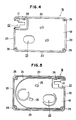
- Figs 4 and 5 show diagrams of the outside surface and the inside surface of the lower case 18.
- the upper case 10 is of a box shape having a tapered side wall 12 along the four sides of an upper wall 11 and a large partition 13 substantially profiling the toy motor-bike and standing in the upper wall 11 at the center thereof.
- the side walls 12 are depressed inwardly to have a shape along a holding portion 3a of the power rack 3 at the upper right corner of the upper case 10, a substantially U-shaped support wall 14 is defined below the depressed portion and one side thereof is opened.
- a cutout 15 is defined at a portion a little inward of the opening of the support wall 14.
- two guide walls 16 are defined around the partition 14 on the inside surface of the upper case 10.
- the guide walls 16 are disposed from the support wall 14 around the partition 13 along three tapered side walls 12 with its corner portion curved to an arc shape.
- Four cylindrical screw holes 17 are defined through three corners and the support wall 14 in the inside wall.
- the lower case 18 has a tapered side wall 20 defined along the four sides of a bottom wall 19 and a U-shaped support wall 21 defined at the corner corresponding to the support wall 14 of the upper case 10 as shown in Fig. 11, the support wall 21 being a little expanded from a surface and confronting with the support wall 14.
- the lower case 18 also has a cutout 22 directed from a location a little nearer to an opening as compared with the location of the support wall 21 to which the cutout 15 defined in the support wall 14 corresponds toward the opening.
- a hole 23 is defined through the bottom wall 19 at a location a little dislocated to a lower left direction from the center of the bottom wall 19.
- a projection 24 is defined on the inside wall of the lower case 18 in correspondence with the two guide walls 16 of the upper case 10 in such a manner that it is interposed therebetween and a pair of holding pieces 25 stand at the center of the inside surface in substantial confrontation.
- Round holes 26 are defined in correspondence with the screw holes 17.
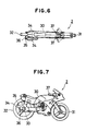
- the toy motor-bike 2 has a front wheel 31 and a rear wheel 32 pivotally supported at the front and the back of a flat body 30, a pinion gear 33 is integrally disposed at the right side surface of the rear wheel 32 and a shaft passing through the rear wheel 32 and the pinion gear 33 is supported by bearing members 34 at opposite sides.
- a vertical width of the bearing members 34 in Fig. 7 is substantially equal to the width between the support walls 14 and 21 in confrontation of the upper case 10 and the lower case 18 when the upper case 10 is placed over the lower case 18, as shown in Fig. 11.
- a support bar 36 projecting inwardly is disposed at the rear end of the inside surface of a side frame 35 for supporting the bearing member 34 on the right side to support the power rack 3 to be meshed with the pinion 33.
- the rack 3 comprises the flat and rectangular holding portion 3a with a round hole defined at the center and a long rack belt 3b extending from the holding portion 3a, the rack belt 3b being flexible and having teeth defined on its one side.
- Fig. 8 is an exploded perspective view of the card case comprising the aforesaid members, wherein when the upper case 10 is placed over the lower case 18 and screws are passed through the round holes 26 and the screw holes 17 from the lower side for threading, the lower projection 24 is engaged a little between the two upper guide walls 16 to form a guide pipe as well as the partition 13 of the upper case 10 and the bottom wall 19 of the lower case 18 form an engaging section into which the toy motor-bike 2 is set.
- the holding pieces 25 stand in the engaging portion in the state that they are set into the cutouts 13a of the partition 13.
- the upper and lower substantially U-shaped support walls 14, 21 confronting each other form a setting portion with one side opened and the upper portion of the upper support wall 14 is cut out to permit the holding portion 3a of the rack 3 to be set thereinto.
- the toy motor-bike 2 is set into the engaging section surrounded by the partition 13 and the body 30 is gripped by a pair of the holding pieces.
- the toy motor-bike 2 can be taken out from the card case 1 by pushing out the toy motor-bike 2 with a finger applied to the hole 23 defined through the bottom wall 19 of the lower case 18, and the power rack 3 can be pulled out as it is by holding the holding portion 3a in the direction shown by the arrow, as shown in Fig. 1.
- the power rack 3 is inserted in the vicinity of the holding portion 3a, the card case 1 is held by one hand and the rear wheel 32 is approached to a floor to complete the preparation for a start.
- the grip portion 3a of the power rack 3 is held by another hand and pulled vigorously obliquely upwardly, the rear wheel 32 serving also as a fly wheel is rotated at a high speed through the rack and the pinion gear 33.
- the toy motor-bike 2 since the toy motor-bike 2 is made to start in the state that it is held by the card case 1, it can start stably at all times and its traveling direction can be set fairly accurately.
- the card case 1 accommodating the toy motor-bike 2 and the power rack 3 makes a card shape, which is convenient for carrying and since there are almost no projected portions on the card case 1, it is not caught by an object and even if the card case 1 dropped, it protects the toy motor-bike 2 from being damaged.
- the toy since power is applied to a movable toy in the state that it is supported in a toy case, the toy can make stable movement at all times and no unnatural force is applied to the movable toy itself so that there is no possibility that the movable toy is damaged.
- the movable toy Since the movable toy starts movement from the state that it is supported by a support means of a toy case, it can move stable at all times, anyone can handle the toy easily and it is not necessary to learn how to operate it for playing a game.
- the movable toy Since the movable toy is engaged with a toy case to be made to a card shape as a whole, it fits to a palm and is very convenient for carrying.
- the movable toy Since the movable toy is engaged with the toy case to be protected securely when it is carried, the movable toy is prevented from being damaged when it strikes against an object or it is dropped. In addition, since there is no projection on the card case, it is not damaged by being caught by an object.
Landscapes
- Toys (AREA)
Claims (4)
- Ensemble formant jouet comportant : un jouet mobile (2), un boîtier généralement rectangulaire (1) relativement mince par rapport à sa longueur et sa largeur et ayant une cavité formée pour recevoir et retenir de manière amovible le jouet à peu près à l'intérieur du volume du boîtier, des moyens formant générateur de puissance (3) pour fournir une puissance au jouet ; un support (14, 21) situé dans le boîtier pour recevoir le jouet en vue de sa propulsion caractérisé en ce que : la cavité épouse sensiblement la forme du jouet ; en ce que le jouet est propulsé de manière manuelle par les moyens formant générateur de puissance qui comportent une crémaillère (3) qui, en utilisation, coopère avec un pignon (33) situé sur le jouet ; en ce que la crémaillère (3) comporte une poignée (3a) et une bande formant crémaillère allongée (3b) contiguë à la poignée, le boîtier ayant une partie formant bord (14) conformée pour recevoir, lorsque la crémaillère n'est pas utilisée, la poignée de crémaillère (3a), et un canal intérieur (16) pour recevoir la bande formant crémaillère ; et en ce que ladite partie formant bord (14) du boîtier (1) est adaptée pour fournir le support (14, 21).
- Ensemble formant jouet selon la revendication 1, dans lequel ladite partie formant bord (14) du boîtier formée pour recevoir la poignée de crémaillère (3a) est située dans un angle du rectangle.
- Ensemble formant jouet selon la revendication 1 ou 2, dans lequel un composant du jouet (2) peut être déplacé entre une position de fonctionnement et une position de rangement, l'épaisseur du jouet dans la position de rangement étant réduite par comparaison avec celle de la position de fonctionnement de telle sorte que le jouet, lorsqu'il est situé dans la cavité située dans le boîtier (1), affleure la surface du boîtier ou est situé en-dessous de la surface du boîtier.
- Ensemble formant jouet selon le revendication 3, dans lequel le jouet est une motocyclette (2) comportant, en tant que dit composant, un jeu de poignées de direction (37) qui sont mobiles entre la position de fonctionnement et la position de rangement.
Applications Claiming Priority (2)
| Application Number | Priority Date | Filing Date | Title |
|---|---|---|---|
| JP31988/88 | 1988-03-10 | ||
| JP3198888 | 1988-03-10 |
Publications (2)
| Publication Number | Publication Date |
|---|---|
| EP0332407A1 EP0332407A1 (fr) | 1989-09-13 |
| EP0332407B1 true EP0332407B1 (fr) | 1993-10-27 |
Family
ID=12346302
Family Applications (1)
| Application Number | Title | Priority Date | Filing Date |
|---|---|---|---|
| EP89302278A Expired - Lifetime EP0332407B1 (fr) | 1988-03-10 | 1989-03-07 | Ensemble jouet |
Country Status (3)
| Country | Link |
|---|---|
| US (1) | US4959035A (fr) |
| EP (1) | EP0332407B1 (fr) |
| DE (1) | DE68910154T2 (fr) |
Families Citing this family (35)
| Publication number | Priority date | Publication date | Assignee | Title |
|---|---|---|---|---|
| USD378769S (en) * | 1993-08-06 | 1997-04-08 | Kabushiki Kaisha Bandai | Top spinner |
| US6676476B1 (en) * | 2003-01-03 | 2004-01-13 | Lund And Company Invention, Llc | Gyroscope figures |
| US7500898B2 (en) * | 2004-08-25 | 2009-03-10 | Jakks Pacific, Incorporation | Toy for rotating and launching an object |
| AU2004322952A1 (en) * | 2004-08-25 | 2006-03-09 | Jakks Pacific, Inc. | Wheel spinning launcher and wheel toy |
| US20060148373A1 (en) * | 2004-08-25 | 2006-07-06 | Jakks Pacific, Inc. | Integrated carrying case and toy object launcher |
| US7594843B2 (en) * | 2004-08-25 | 2009-09-29 | Jakks Pacific, Inc. | Toy having an electronic interactive device that is responsive to a rotated and launched object |
| US20060099879A1 (en) * | 2004-08-25 | 2006-05-11 | Jakks Pacific, Inc. | Toy for rotating and launching an object and spraying water proximate the object |
| US20060099880A1 (en) * | 2004-08-25 | 2006-05-11 | Jakks Pacific, Inc. | Arm attachable toy for rotating and launching an object |
| US7445539B2 (en) * | 2004-08-25 | 2008-11-04 | Jakks Pacific, Incorporated | Toy vehicle with a detachably attachable wheel |
| US7568578B2 (en) * | 2004-11-01 | 2009-08-04 | Stephen Berman | Wheel spinning toy vehicle in blister package with clutch mechanism |
| US20060272627A1 (en) * | 2005-06-06 | 2006-12-07 | Mattel, Inc. | Toy projectile launching devices |
| GB2427429A (en) * | 2005-06-21 | 2006-12-27 | Gregory R Mccormick | Operating device for a window covering |
| US7950976B2 (en) * | 2005-07-14 | 2011-05-31 | Jakks Pacific, Inc. | Toy for rotating and launching an object |
| USD574442S1 (en) * | 2005-10-24 | 2008-08-05 | Jakes Pacific, Inc. | Handheld launcher for launching a toy wheel |
| US7841538B2 (en) * | 2007-10-31 | 2010-11-30 | Target Brands, Inc. | Transaction product with memory |
| US8388405B2 (en) * | 2009-10-30 | 2013-03-05 | Hasbro, Inc. | Toy launcher and dual powered toy |
| CN201747212U (zh) * | 2010-08-04 | 2011-02-16 | 希美克(广州)实业有限公司 | 内置百叶帘的新型中空玻璃装置 |
| JP3164823U (ja) * | 2010-10-06 | 2010-12-16 | 株式会社タカラトミー | コマ玩具発射装置 |
| US9114327B2 (en) | 2010-10-08 | 2015-08-25 | Mattel, Inc. | Toy playset |
| JP5801101B2 (ja) * | 2011-04-18 | 2015-10-28 | 株式会社タカラトミー | バックスピントイ |
| US8920209B2 (en) | 2011-04-24 | 2014-12-30 | Hasbro, Inc. | Spinning toy apparatus |
| CN202315282U (zh) * | 2011-10-31 | 2012-07-11 | 广东奥飞动漫文化股份有限公司 | 一种可分离的组合式玩具陀螺 |
| US9821245B2 (en) * | 2012-04-18 | 2017-11-21 | Lego A/S | Toy building set |
| JP2014076232A (ja) * | 2012-10-12 | 2014-05-01 | Tomy Co Ltd | バックスピントイ |
| US9394095B2 (en) | 2012-12-29 | 2016-07-19 | Target Brands, Inc. | Transaction product assembly with separable parts for reassembly |
| US9707488B2 (en) | 2013-05-03 | 2017-07-18 | Mattel, Inc. | Toy vehicle, launching apparatus therefor and methods of using the same |
| US9427671B2 (en) | 2014-05-30 | 2016-08-30 | Mattel, Inc. | Toy vehicle launcher and toy track for use therewith |
| EP3247478B1 (fr) * | 2015-01-21 | 2019-06-26 | Lego A/S | Jouet comprenant un rotor, un mécanisme d'activation et un dispositif de lancement |
| US10758833B2 (en) | 2017-08-29 | 2020-09-01 | Hasbro, Inc. | Toy car launcher apparatus |
| US10702767B2 (en) | 2017-12-14 | 2020-07-07 | Hasbro, Inc. | Integrated multi environment interactive battle game |
| USD877260S1 (en) * | 2018-10-24 | 2020-03-03 | Tomy Company, Ltd. | Winder for launching apparatus for spinning top toy |
| US11154769B2 (en) | 2018-11-01 | 2021-10-26 | Tomy Company, Ltd. | Interactive tops collision enhancing battling environment |
| US11311796B2 (en) | 2019-08-29 | 2022-04-26 | Tomy Company, Ltd. | Playing surface for spinning top toy apparatus and methods |
| BR112022014110A2 (pt) | 2020-01-17 | 2022-09-27 | Hasbro Inc | Estádio para uma batalha entre piões giratórios, aparelho de partidas de estádio de batalhas e método de jogo |
| CN113713402B (zh) * | 2020-05-25 | 2025-06-27 | 广州灵动创想文化科技有限公司 | 一种弹射结构及弹射玩具 |
Family Cites Families (7)
| Publication number | Priority date | Publication date | Assignee | Title |
|---|---|---|---|---|
| US3026642A (en) * | 1959-05-14 | 1962-03-27 | John W Ryan | Firearm actuating buckle |
| US3701216A (en) * | 1971-12-22 | 1972-10-31 | California R & D Center | Wheel apparatus and rack and pinion launcher enabling repeated strokes and having automatic ejector |
| US4087935A (en) * | 1976-11-26 | 1978-05-09 | Mattel, Inc. | Toy vehicle with housing |
| US4473969A (en) * | 1980-04-21 | 1984-10-02 | Wilson Paul A | Housing for spring wound toy |
| JPS5886192A (ja) * | 1981-11-17 | 1983-05-23 | 益田 靖嗣 | 電気洗濯機及び之による洗濯法 |
| FR2549382B1 (fr) * | 1983-07-21 | 1986-02-21 | Joustra Sa | Jouet comportant un vehicule miniature |
| US4690654A (en) * | 1985-11-18 | 1987-09-01 | Craft House Corporation | Toy vehicle carrying case and launcher |
-
1988
- 1988-11-04 US US07/267,036 patent/US4959035A/en not_active Expired - Fee Related
-
1989
- 1989-03-07 EP EP89302278A patent/EP0332407B1/fr not_active Expired - Lifetime
- 1989-03-07 DE DE89302278T patent/DE68910154T2/de not_active Expired - Fee Related
Also Published As
| Publication number | Publication date |
|---|---|
| EP0332407A1 (fr) | 1989-09-13 |
| DE68910154D1 (de) | 1993-12-02 |
| DE68910154T2 (de) | 1994-04-28 |
| US4959035A (en) | 1990-09-25 |
Similar Documents
| Publication | Publication Date | Title |
|---|---|---|
| EP0332407B1 (fr) | Ensemble jouet | |
| US4087935A (en) | Toy vehicle with housing | |
| US4183173A (en) | Toy assembly with interchangeable parts and detachable appendages | |
| US4526554A (en) | Toy motorcycle and launcher apparatus | |
| CA1184766A (fr) | Accelerateur de vehicule-jouet | |
| US4188748A (en) | Toy vehicle and housing set | |
| JPH0111277Y2 (fr) | ||
| JPS6133597B2 (fr) | ||
| IT8268065A1 (it) | Motoveicolo ad uso giocattolo particolarmente motocicletta | |
| US3382609A (en) | Electrically powered tethered toy | |
| US6517408B1 (en) | Flywheel powered bicycle with an articulated rider | |
| CN201807190U (zh) | 用于发射玩具车的发射器及其配合使用的玩具车 | |
| US5310375A (en) | Small decoration equipped with spring-operated movable decorative element | |
| US3477172A (en) | Mechanical toy | |
| US4016675A (en) | Push toy | |
| GB2130903A (en) | Launcher for toy vehicle | |
| EP0356089A3 (fr) | Véhicule jouet | |
| CN216536905U (zh) | 一种可弹射陀螺的玩具机甲 | |
| JPH0354792Y2 (fr) | ||
| US6116984A (en) | Pop-out toy | |
| CN221637320U (zh) | 钳形陀螺玩具 | |
| CN223586565U (zh) | 一种泡泡玩具 | |
| JP2538401Y2 (ja) | 走行玩具起動装置 | |
| JPH0429669Y2 (fr) | ||
| JPH0751119Y2 (ja) | 遊泳動物玩具 |
Legal Events
| Date | Code | Title | Description |
|---|---|---|---|
| PUAI | Public reference made under article 153(3) epc to a published international application that has entered the european phase |
Free format text: ORIGINAL CODE: 0009012 |
|
| AK | Designated contracting states |
Kind code of ref document: A1 Designated state(s): DE FR GB |
|
| 17P | Request for examination filed |
Effective date: 19891102 |
|
| 17Q | First examination report despatched |
Effective date: 19900704 |
|
| GRAA | (expected) grant |
Free format text: ORIGINAL CODE: 0009210 |
|
| AK | Designated contracting states |
Kind code of ref document: B1 Designated state(s): DE FR GB |
|
| REF | Corresponds to: |
Ref document number: 68910154 Country of ref document: DE Date of ref document: 19931202 |
|
| ET | Fr: translation filed | ||
| PLBE | No opposition filed within time limit |
Free format text: ORIGINAL CODE: 0009261 |
|
| STAA | Information on the status of an ep patent application or granted ep patent |
Free format text: STATUS: NO OPPOSITION FILED WITHIN TIME LIMIT |
|
| 26N | No opposition filed | ||
| PGFP | Annual fee paid to national office [announced via postgrant information from national office to epo] |
Ref country code: GB Payment date: 19950302 Year of fee payment: 7 |
|
| PGFP | Annual fee paid to national office [announced via postgrant information from national office to epo] |
Ref country code: FR Payment date: 19950320 Year of fee payment: 7 |
|
| PGFP | Annual fee paid to national office [announced via postgrant information from national office to epo] |
Ref country code: DE Payment date: 19950328 Year of fee payment: 7 |
|
| PG25 | Lapsed in a contracting state [announced via postgrant information from national office to epo] |
Ref country code: GB Effective date: 19960307 |
|
| GBPC | Gb: european patent ceased through non-payment of renewal fee |
Effective date: 19960307 |
|
| PG25 | Lapsed in a contracting state [announced via postgrant information from national office to epo] |
Ref country code: FR Effective date: 19961129 |
|
| PG25 | Lapsed in a contracting state [announced via postgrant information from national office to epo] |
Ref country code: DE Effective date: 19961203 |
|
| REG | Reference to a national code |
Ref country code: FR Ref legal event code: ST |