EP0341377A2 - Dispositif pour relever et empiler des disques avec un trou central découpé d'un feuillard de matériaux - Google Patents
Dispositif pour relever et empiler des disques avec un trou central découpé d'un feuillard de matériaux Download PDFInfo
- Publication number
- EP0341377A2 EP0341377A2 EP89102206A EP89102206A EP0341377A2 EP 0341377 A2 EP0341377 A2 EP 0341377A2 EP 89102206 A EP89102206 A EP 89102206A EP 89102206 A EP89102206 A EP 89102206A EP 0341377 A2 EP0341377 A2 EP 0341377A2
- Authority
- EP
- European Patent Office
- Prior art keywords
- finger
- sleeve
- cart
- material web
- conveyor belt
- Prior art date
- Legal status (The legal status is an assumption and is not a legal conclusion. Google has not performed a legal analysis and makes no representation as to the accuracy of the status listed.)
- Withdrawn
Links
- 239000000463 material Substances 0.000 title claims abstract description 37
- 238000004080 punching Methods 0.000 claims description 21
- 239000012858 resilient material Substances 0.000 claims description 4
- 239000013013 elastic material Substances 0.000 claims description 3
- 239000006260 foam Substances 0.000 claims description 3
- 230000002040 relaxant effect Effects 0.000 claims 1
- 230000001360 synchronised effect Effects 0.000 claims 1
- 238000013461 design Methods 0.000 description 2
- 238000000034 method Methods 0.000 description 2
- 238000010276 construction Methods 0.000 description 1
- 238000011161 development Methods 0.000 description 1
- 238000006073 displacement reaction Methods 0.000 description 1
- 230000000694 effects Effects 0.000 description 1
- 238000003780 insertion Methods 0.000 description 1
- 230000037431 insertion Effects 0.000 description 1
- 238000011089 mechanical engineering Methods 0.000 description 1
- 238000012545 processing Methods 0.000 description 1
- 230000002441 reversible effect Effects 0.000 description 1
- 238000007789 sealing Methods 0.000 description 1
- 239000002699 waste material Substances 0.000 description 1
Images


Classifications
-
- B—PERFORMING OPERATIONS; TRANSPORTING
- B21—MECHANICAL METAL-WORKING WITHOUT ESSENTIALLY REMOVING MATERIAL; PUNCHING METAL
- B21D—WORKING OR PROCESSING OF SHEET METAL OR METAL TUBES, RODS OR PROFILES WITHOUT ESSENTIALLY REMOVING MATERIAL; PUNCHING METAL
- B21D43/00—Feeding, positioning or storing devices combined with, or arranged in, or specially adapted for use in connection with, apparatus for working or processing sheet metal, metal tubes or metal profiles; Associations therewith of cutting devices
- B21D43/20—Storage arrangements; Piling or unpiling
- B21D43/22—Devices for piling sheets
-
- B—PERFORMING OPERATIONS; TRANSPORTING
- B21—MECHANICAL METAL-WORKING WITHOUT ESSENTIALLY REMOVING MATERIAL; PUNCHING METAL
- B21D—WORKING OR PROCESSING OF SHEET METAL OR METAL TUBES, RODS OR PROFILES WITHOUT ESSENTIALLY REMOVING MATERIAL; PUNCHING METAL
- B21D43/00—Feeding, positioning or storing devices combined with, or arranged in, or specially adapted for use in connection with, apparatus for working or processing sheet metal, metal tubes or metal profiles; Associations therewith of cutting devices
- B21D43/02—Advancing work in relation to the stroke of the die or tool
- B21D43/18—Advancing work in relation to the stroke of the die or tool by means in pneumatic or magnetic engagement with the work
-
- B—PERFORMING OPERATIONS; TRANSPORTING
- B65—CONVEYING; PACKING; STORING; HANDLING THIN OR FILAMENTARY MATERIAL
- B65G—TRANSPORT OR STORAGE DEVICES, e.g. CONVEYORS FOR LOADING OR TIPPING, SHOP CONVEYOR SYSTEMS OR PNEUMATIC TUBE CONVEYORS
- B65G61/00—Use of pick-up or transfer devices or of manipulators for stacking or de-stacking articles not otherwise provided for
-
- B—PERFORMING OPERATIONS; TRANSPORTING
- B65—CONVEYING; PACKING; STORING; HANDLING THIN OR FILAMENTARY MATERIAL
- B65H—HANDLING THIN OR FILAMENTARY MATERIAL, e.g. SHEETS, WEBS, CABLES
- B65H29/00—Delivering or advancing articles from machines; Advancing articles to or into piles
-
- B—PERFORMING OPERATIONS; TRANSPORTING
- B65—CONVEYING; PACKING; STORING; HANDLING THIN OR FILAMENTARY MATERIAL
- B65H—HANDLING THIN OR FILAMENTARY MATERIAL, e.g. SHEETS, WEBS, CABLES
- B65H2301/00—Handling processes for sheets or webs
- B65H2301/40—Type of handling process
- B65H2301/42—Piling, depiling, handling piles
- B65H2301/422—Handling piles, sets or stacks of articles
Definitions
- the invention relates to a receiving and stacking device for e.g. in the case of a cart punching disks punched out of a material web with a central hole.
- Such disks are usually taken out of the material web by hand after punching or, in the case of a so-called break-out device, are pushed through a plunger downwards over a perforated table top.
- the stripping device with the perforated table top does not always work to satisfaction, since the panes may tip over and not fall cleanly on a stack.
- the perforated table top must match the punch pattern exactly, so it must always be adapted to the punch pattern.
- a finger which can be lowered at least so far into the central hole of the disc with its lower end that a radially expandable sleeve lies in the region of the central hole and the disc can be clamped onto it by expanding it and with the Fingers can be raised and released again after the cuff is relaxed.
- the finger can also be inserted through the center hole until the disc sits above the expandable cuff and is prevented from sliding downward after the cuff has expanded.
- the finger according to the invention can therefore first be inserted through the center hole of the disk when the cuff is not expanded.
- the cuff is then expanded to clamp the disc on the cuff or, when the cuff is below the disc, the largest diameter of the cuff is larger than the inside diameter of the center hole of the disc.
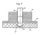
- the disc In this expanded state of the cuff, the disc can be lifted up with the finger and placed on a stack.
- the finger can also be placed one after the other on several discs with a center hole in order to lift them up, whereby the cuff is briefly transferred to its unexpanded (relaxed) position shortly before the cuff is inserted through the respective (next) disc in order to pass through the To be able to be pushed through the center hole in order to then be expanded again, so that the pane in question can no longer slide downward.
- the reversible expansion of the cuff can be accomplished by means of a further advantageous feature of the invention in that the finger is connected to a pressure medium supply via which pressure medium e.g. Compressed air, can be fed.
- pressure medium e.g. Compressed air
- the cuff which is made of resilient material, bulges out, so that the disks located above the cuff can be lifted with a finger.
- the discs picked up on the finger can be put down or stripped off. In this way, disks with different center hole size and shape can be excavated with one and the same finger.
- the cuff can, in a further embodiment of the invention, on a radial one that is preferably distributed over the circumference Bores provided sleeve of the finger sit, the interior of which the pressure medium can be fed.
- the radial bores connect the interior of the sleeve which can be pressurized with the inner surface of the sleeve, which can be substantially uniformly bulged all around when the radial bores are distributed over the circumference of the sleeve.
- the radial bores can also open into groove grooves running around the outside of the sleeve.
- the finger can have a rounded cap at its lower end.
- the sleeve is inserted tightly and firmly in the finger, for example between an upper section connected to the pressure medium supply and the lower cap, so that the pressure medium is available for the expansion of the cuff with as little loss as possible.
- a simple assembly of the cuff in the finger is possible in that the sleeve has a thread at its lower end, onto which the cap is screwed. The cuff can then be clamped between said upper portion of the finger and the cap.
- the cuff is preferably supported downwards by the cap in order to maintain a secure position in the finger.
- the finger including the cap is essentially hollow-cylindrical in the area of the cuff and the cuff with an upper and / or lower, preferably tapered edge is received in an inner edge recess of the upper section of the finger or the lower cap and is supported radially outwards.
- the material web that has already been punched and still contains the disks to be picked up is advantageously transferred to a base made of resilient material, such as a soft foam.
- the thickness of the pad is such that the finger, with the cuff relaxed, can be inserted so far through the central hole of the disc to be picked up from the pad by elastic dodging of the underlay material that the cuff is in the area or under that on the top and disc to be picked up comes to rest.
- the finger is height-adjustable and preferably interchangeably attached to the holder of a trolley which can be moved transversely and / or longitudinally to the material web.
- a construction similar to that used for a cart punch can be used, but of a simpler design, since the forces that occur with a punch do not occur.
- the support for the stamped material web can be designed as a conveyor belt running under the movement area of the carriage, which can be moved transversely to the stamped material web.
- the cart can preferably be moved on the upper cross part of a substantially U-shaped machine stand, as is known per se for the cart in a cart punch.
- a further conveyor belt is provided on the side of the base of the stamped material web, which is preferably designed as a conveyor belt, also below the transverse part of the machine stand, for the storage of the disks, which may be combined into a stack.
- this conveyor belt By means of this conveyor belt, the picked up disks can be fed individually or in a stack for further processing or determination.
- a fork-shaped scraper can be arranged above the further conveyor belt, into which the finger can be inserted laterally with a section above the disks held by the expanded sleeve. If the finger is inserted into the scraper after the section has been retracted laterally above the picked-up disks and then pulled up, when the cuff relaxes, the picked-up disks reliably fall down in a stack onto the further conveyor belt.
- the support which is designed as a conveyor belt, for the punched material web is arranged in a continuation of the punching table of an associated punching machine, preferably a cart punching machine.
- the material transport from the punch to the receiving and stacking device according to the invention is short and fast.
- the punched-out perforated disks are fed to the receiving and stacking device in the same sequence or the same pattern as they have been punched out of the material web.
- Material drive an assigned punching machine, preferably cart punching machine, to run, so that all perforated disks punched out of the material web can be immediately lifted and stacked without backing up or unwanted waiting times in the picking and stacking device according to the invention.
- an assigned punching machine preferably cart punching machine
- the movement of the carriage for the finger can be programmable according to any given punching pattern, so that the structure of the pick-up and stacking device according to the invention can be used unchanged for the most varied punching patterns.
- the movement of the cart for the finger can be programmed in the same way as the movement of the cart of an assigned cart punch, so that the fingers for receiving the sheet of material punched out of the material web and transferred onto the base of the receiving and stacking device each takes the right position.
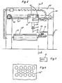
- the receiving and stacking device 61 shown in FIG. 1 can correspond in principle to a cart punch 60 as shown there in addition to the device 61.
- the cart punch 60 has a machine stand 1, on the upper cross part 1 'a guide 1' is provided, along which a cart 2 can run on rollers 3.
- the carriage 2 is driven by a chain and a geared brake motor 5.
- the drive can also be carried out by other elements that are common in mechanical engineering.
- the medium required for the punching stroke is supplied via a flexible feed 7.
- a piston 8 is guided in the cart 2 so that it can move up and down.
- the piston 8 carries a pressure foot 9, on which a knife receiving plate 11 is held with a punch knife 13 via a guide bracket 10.
- the knife receiving plate 11 is secured against displacement by an adjusting screw 12.
- the material web 48 to be punched is guided by transport rollers 36 over a punching table 6 formed by the machine frame 1.
- a piston-cylinder arrangement 35 is formed on the transversely movable carriage 34, to which the required medium is supplied via feeds 47.
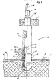
- the piston rod 54 of the piston-cylinder arrangement 35 carries a holder 21 with a vertically downward pointing finger 20, the structure of which is illustrated in detail in FIG. 5
- the finger 20 is interchangeably clamped in the holder 21 at its upper end 20.
- a pressure medium connection 25 connects to a pressure medium supply line 26.
- a pressure medium is guided into the interior 55 of the finger 20 via this.
- a sleeve 22 is tightly and permanently fastened in the finger 20 adjacent to the interior 55.
- the sleeve 22 has radial bores 24 distributed over the circumference, which open into puncture grooves 23 provided in the outer circumference of the sleeve 22.
- the sleeve 22 has at its lower end 22 'a thread for screwing on a cap 64.
- a sleeve 27 made of elastically resilient material, e.g.
- the cuff 27 has an upper and a lower tapered edge 50, 51, which are each received in inner edge recesses 52, 53 of the upper section of the finger 20 or the cap 64 and are supported there in a sealing manner to the outside.
- the middle section of the sleeve 27 between the upper section of the finger 20 and the lower cap 64 forms the outer jacket of the finger 20 in this area.
- the interior 55 of the upper section of the finger 20 is in flow connection with the interior 56 of the rigid sleeve 22, so that at Pressurization via the pressure medium connection 25 Pressure via the radial bores 24 and the puncture grooves 23 is present on the inner surface of the sleeve 27. Under the effect of the pressure, the cuff 27 can expand radially, as indicated on the bulge 28, since its two edges 50 and 51 are clamped airtight between the sleeve 22 and the upper section of the finger 20 or the cap 64.
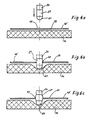
- the punched material web 48 ' is at this time on the top 46 of the elastic material, for example soft foam, existing pad 30 of such a thickness that the finger 20 by compressing the elastic material so far through the center hole 49th can be passed until the sleeve 27 reaches or lies below the area of the disk 29 to be accommodated.
- the pressure medium supply to the finger 20 is controlled in such a way that the pressure medium escapes from the cuff 27 immediately when the latter is immersed in the center hole 49 of the disk 29 and the pressure medium is supplied again at the lowest point after the finger 20 is immersed, the cuff 27 bulges in order to clamp the disc 29 or to hold it above itself.
- the support 30 designed as a conveyor belt, onto which the punched material web 48 'is transferred runs approximately synchronously with the transport rollers 26 of the cart punch 1. After the disks 29 have been taken out of the material web 48', the remaining material web remainder 48 'is carried away as waste.
- the pick-up and stacking device 61 and the cart punch 60 can be programmed for the most varied but identical punching patterns.
- the number of perforated disk 29 to be accommodated can also be set as desired up to a maximum number.
- the holder 21 is attached with the finger 20 directly to the cart 2 of the cart punch so that it stands above the base 30 and with the drive means provided for the cart 2 is movable.
- the finger 20 can be spatially adjustable relative to the punched image, for example using clamping screws 62. In this way, the punching process starts in the same cycle.
- the trolley 2 can make a separate transverse movement at intervals in order to deposit the respective partial stack arising on the finger 20 until the finger 20 is above the conveyor belt 31.
Landscapes
- Engineering & Computer Science (AREA)
- Mechanical Engineering (AREA)
- Automatic Disk Changers (AREA)
- Perforating, Stamping-Out Or Severing By Means Other Than Cutting (AREA)
- Delivering By Means Of Belts And Rollers (AREA)
Applications Claiming Priority (2)
| Application Number | Priority Date | Filing Date | Title |
|---|---|---|---|
| DE3816266 | 1988-05-12 | ||
| DE19883816266 DE3816266A1 (de) | 1988-05-12 | 1988-05-12 | Aufnahme- und stapelvorrichtung fuer aus einer materialbahn aus gestanzten scheiben mit mittelloch |
Publications (2)
| Publication Number | Publication Date |
|---|---|
| EP0341377A2 true EP0341377A2 (fr) | 1989-11-15 |
| EP0341377A3 EP0341377A3 (fr) | 1990-06-06 |
Family
ID=6354255
Family Applications (1)
| Application Number | Title | Priority Date | Filing Date |
|---|---|---|---|
| EP89102206A Withdrawn EP0341377A3 (fr) | 1988-05-12 | 1989-02-09 | Dispositif pour relever et empiler des disques avec un trou central découpé d'un feuillard de matériaux |
Country Status (2)
| Country | Link |
|---|---|
| EP (1) | EP0341377A3 (fr) |
| DE (1) | DE3816266A1 (fr) |
Cited By (14)
| Publication number | Priority date | Publication date | Assignee | Title |
|---|---|---|---|---|
| DE10332018B3 (de) * | 2003-07-15 | 2005-01-13 | Heinrich Georg Gmbh Maschinenfabrik | Vorrichtung zum Halten von abgestapelten Blechen, insbesondere Transformatorblechen |
| DE202011105725U1 (de) * | 2011-09-16 | 2011-12-19 | Schunk Gmbh & Co. Kg Spann- Und Greiftechnik | Lochgreifer |
| EP2570243A1 (fr) | 2011-09-16 | 2013-03-20 | Schunk GmbH & Co. KG Spann- und Greiftechnik | Grappin pour trous |
| CN104056989A (zh) * | 2014-06-05 | 2014-09-24 | 昆山宝锦激光拼焊有限公司 | 一种履带式镭焊料出料装置 |
| CN104139982A (zh) * | 2014-07-18 | 2014-11-12 | 歌尔声学股份有限公司 | 冲压收料摆盘机 |
| CN104308027A (zh) * | 2014-10-08 | 2015-01-28 | 天津英浩电子有限公司 | 一种冲压模具用废料自动收集装置 |
| CN104369121A (zh) * | 2014-11-24 | 2015-02-25 | 盐城市华森机械有限公司 | 砂盘冲压机 |
| CN105665503A (zh) * | 2016-02-24 | 2016-06-15 | 东莞市银通机械科技有限公司 | 一种自动上下料的全自动油压机生产线 |
| CN106078917A (zh) * | 2016-07-06 | 2016-11-09 | 东莞市开方实业有限公司 | 一种柔性电路板的全自动冲切机 |
| CN106270258A (zh) * | 2016-08-30 | 2017-01-04 | 天津恒兴机械设备有限公司 | 一种自动化的冲压模具用废料收集装置 |
| CN108466859A (zh) * | 2018-03-30 | 2018-08-31 | 重庆华康印务有限公司 | 一种发票收集装置 |
| CN109175077A (zh) * | 2018-10-18 | 2019-01-11 | 佛山市南海鑫隆机工机械有限公司 | 一种打孔取料同步工作的加工设备 |
| EP3614406A1 (fr) * | 2018-08-23 | 2020-02-26 | Heinrich Georg GmbH Maschinenfabrik | Boulon d'enfilage ainsi que table d'empilage du noyau, plateforme de construction, dispositif d'empilage ou analogue doté d'au moins un boulon d'enfilage |
| CN121651122A (zh) * | 2026-02-05 | 2026-03-13 | 宁波市创捷自动化有限公司 | 一种车用电池包钢边条的自动码垛装置 |
Families Citing this family (4)
| Publication number | Priority date | Publication date | Assignee | Title |
|---|---|---|---|---|
| CN110774344B (zh) * | 2019-11-06 | 2021-06-08 | 长兴小浦凯荣机械加工厂 | 一种方便收集废屑的汽车装饰条生产装置 |
| CN111267173B (zh) * | 2020-02-27 | 2021-09-21 | 丁程 | 一种教育用订书钉去除装置 |
| CN113523139A (zh) * | 2021-08-29 | 2021-10-22 | 东莞威仕达汽车零部件有限公司 | 一种自动冲压码跺机 |
| CN115945581A (zh) * | 2022-12-05 | 2023-04-11 | 江西犀瑞刀片制造有限公司 | 一种刀片冲切机 |
Family Cites Families (7)
| Publication number | Priority date | Publication date | Assignee | Title |
|---|---|---|---|---|
| FR2126917B1 (fr) * | 1971-01-15 | 1974-08-19 | Saint Gobain Pont A Mousson | |
| DE2225201C2 (de) * | 1972-05-24 | 1981-12-17 | Benz & Hilgers GmbH, 4000 Düsseldorf | Vorrichtung zum Vereinzeln von ineinander gestapelten, konischen Bechern |
| CH602211A5 (fr) * | 1976-02-14 | 1978-07-31 | Schuler Gmbh L | |
| DE3127209A1 (de) * | 1981-07-10 | 1983-01-27 | Fried. Krupp Gmbh, 4300 Essen | "greifvorrichtung" |
| DE3501692A1 (de) * | 1985-01-19 | 1986-07-24 | Maschinenfabrik Fr. Niepmann GmbH u. Co, 5820 Gevelsberg | Vorrichtung zum entladen einzelner bobinen von einer unterlage |
| DE3504100C2 (de) * | 1985-02-07 | 1996-05-09 | Friedhelm Sommer | Druckmittelbetätigter Lochgreifer |
| DE3639271A1 (de) * | 1986-11-17 | 1988-05-26 | Krauss Maffei Ag | Werkzeug zur erfassung eines in einer blasformmaschine geblasenen flaschenartigen hohlkoerpers |
-
1988
- 1988-05-12 DE DE19883816266 patent/DE3816266A1/de not_active Withdrawn
-
1989
- 1989-02-09 EP EP89102206A patent/EP0341377A3/fr not_active Withdrawn
Cited By (19)
| Publication number | Priority date | Publication date | Assignee | Title |
|---|---|---|---|---|
| DE10332018B3 (de) * | 2003-07-15 | 2005-01-13 | Heinrich Georg Gmbh Maschinenfabrik | Vorrichtung zum Halten von abgestapelten Blechen, insbesondere Transformatorblechen |
| DE102012208185B4 (de) * | 2011-09-16 | 2015-05-13 | Schunk Gmbh & Co. Kg Spann- Und Greiftechnik | Lochgreifer |
| DE202011105725U1 (de) * | 2011-09-16 | 2011-12-19 | Schunk Gmbh & Co. Kg Spann- Und Greiftechnik | Lochgreifer |
| EP2570243A1 (fr) | 2011-09-16 | 2013-03-20 | Schunk GmbH & Co. KG Spann- und Greiftechnik | Grappin pour trous |
| DE102012208185A1 (de) | 2011-09-16 | 2013-03-21 | Schunk Gmbh & Co. Kg Spann- Und Greiftechnik | Lochgreifer |
| CN104056989A (zh) * | 2014-06-05 | 2014-09-24 | 昆山宝锦激光拼焊有限公司 | 一种履带式镭焊料出料装置 |
| CN104056989B (zh) * | 2014-06-05 | 2016-01-20 | 昆山宝锦激光拼焊有限公司 | 一种履带式镭焊料出料装置 |
| CN104139982A (zh) * | 2014-07-18 | 2014-11-12 | 歌尔声学股份有限公司 | 冲压收料摆盘机 |
| CN104308027A (zh) * | 2014-10-08 | 2015-01-28 | 天津英浩电子有限公司 | 一种冲压模具用废料自动收集装置 |
| CN104369121A (zh) * | 2014-11-24 | 2015-02-25 | 盐城市华森机械有限公司 | 砂盘冲压机 |
| CN105665503B (zh) * | 2016-02-24 | 2017-10-10 | 东莞市银通机械科技有限公司 | 一种自动上下料的全自动油压机生产线 |
| CN105665503A (zh) * | 2016-02-24 | 2016-06-15 | 东莞市银通机械科技有限公司 | 一种自动上下料的全自动油压机生产线 |
| CN106078917A (zh) * | 2016-07-06 | 2016-11-09 | 东莞市开方实业有限公司 | 一种柔性电路板的全自动冲切机 |
| CN106270258A (zh) * | 2016-08-30 | 2017-01-04 | 天津恒兴机械设备有限公司 | 一种自动化的冲压模具用废料收集装置 |
| CN108466859A (zh) * | 2018-03-30 | 2018-08-31 | 重庆华康印务有限公司 | 一种发票收集装置 |
| EP3614406A1 (fr) * | 2018-08-23 | 2020-02-26 | Heinrich Georg GmbH Maschinenfabrik | Boulon d'enfilage ainsi que table d'empilage du noyau, plateforme de construction, dispositif d'empilage ou analogue doté d'au moins un boulon d'enfilage |
| CN109175077A (zh) * | 2018-10-18 | 2019-01-11 | 佛山市南海鑫隆机工机械有限公司 | 一种打孔取料同步工作的加工设备 |
| CN109175077B (zh) * | 2018-10-18 | 2023-09-08 | 佛山市南海鑫隆机工机械有限公司 | 一种打孔取料同步工作的加工设备 |
| CN121651122A (zh) * | 2026-02-05 | 2026-03-13 | 宁波市创捷自动化有限公司 | 一种车用电池包钢边条的自动码垛装置 |
Also Published As
| Publication number | Publication date |
|---|---|
| DE3816266A1 (de) | 1989-11-23 |
| EP0341377A3 (fr) | 1990-06-06 |
Similar Documents
| Publication | Publication Date | Title |
|---|---|---|
| EP0341377A2 (fr) | Dispositif pour relever et empiler des disques avec un trou central découpé d'un feuillard de matériaux | |
| DE3700601A1 (de) | Schaelmaschine | |
| EP0093318A2 (fr) | Machine à découenner | |
| DE2824488A1 (de) | Vorrichtung zum durchtrennen von werkstoffen | |
| EP0252418A1 (fr) | Guillotine | |
| EP4292785A1 (fr) | Machine de découpe et procédé de découpe d'une pièce de produit en tranches | |
| EP0699395B1 (fr) | Dispositif pour la coupe en tranches de ballots | |
| DE2850985C2 (de) | Vorrichtung zum Zertrennen von Reifenaufbaumaterial in Stücke | |
| EP0074041B1 (fr) | Dispositif de découpe pour des pièces plates | |
| DE10230365A1 (de) | Verfahren zum Heraustrennen von Kunstoffkarten | |
| EP0193750A2 (fr) | Dispositif pour effiler des fils d'un tissu | |
| DE3441198C2 (fr) | ||
| EP0811438B1 (fr) | Dispositif de coupe et d'encochage pour des tôles perforées | |
| EP1704973B2 (fr) | Méthode et appareil pour couper des produits alimentaires allongés | |
| DE2322976A1 (de) | Vorrichtung zum portionieren empfindlicher weicher, scheibenfoermiger gueter | |
| DE3109862A1 (de) | Schnittwerkzeug mit mehreren lochstempeln zum gleichzeitigen lochen von plattenfoermigen werkstuecken | |
| DE19740008C1 (de) | Messersatzwechselvorrichtung für eine Kreismesserschere zum Längsspalten von Metallband | |
| DE10051098B4 (de) | Vorrichtung zum Niederhalten von Stanzgut | |
| DE3936083C2 (fr) | ||
| DE29913221U1 (de) | Schneidevorrichtung | |
| DE2631818B2 (de) | Zigarrenperforiereinrichtung | |
| DE102010026409A1 (de) | Verfahren und Vorrichtung zum Durchtrennen einer laufenden Materialbahn | |
| DE2804858C2 (de) | Vorrichtung zum Entfernen der an den Anodennippeln von Anodenstangen angeordneten Gußhülsen | |
| DE19936854C1 (de) | Vorrichtung zum Einschneiden von Löchern in eine laufende Bahn und zum Entfernen der Ausschnitte | |
| WO2018157988A1 (fr) | Dispositif destiné à la séparation des couches externes de parties de produits alimentaires |
Legal Events
| Date | Code | Title | Description |
|---|---|---|---|
| PUAI | Public reference made under article 153(3) epc to a published international application that has entered the european phase |
Free format text: ORIGINAL CODE: 0009012 |
|
| AK | Designated contracting states |
Kind code of ref document: A2 Designated state(s): CH FR IT LI |
|
| PUAL | Search report despatched |
Free format text: ORIGINAL CODE: 0009013 |
|
| AK | Designated contracting states |
Kind code of ref document: A3 Designated state(s): CH FR IT LI |
|
| 17P | Request for examination filed |
Effective date: 19901206 |
|
| 17Q | First examination report despatched |
Effective date: 19910920 |
|
| RAP1 | Party data changed (applicant data changed or rights of an application transferred) |
Owner name: SCHOEN & CIE. AG |
|
| STAA | Information on the status of an ep patent application or granted ep patent |
Free format text: STATUS: THE APPLICATION HAS BEEN WITHDRAWN |
|
| 18W | Application withdrawn |
Withdrawal date: 19921224 |