EP0350074B1 - Méthode et dispositif de mesure du contenu d'un récipient de stockage - Google Patents
Méthode et dispositif de mesure du contenu d'un récipient de stockage Download PDFInfo
- Publication number
- EP0350074B1 EP0350074B1 EP19890112499 EP89112499A EP0350074B1 EP 0350074 B1 EP0350074 B1 EP 0350074B1 EP 19890112499 EP19890112499 EP 19890112499 EP 89112499 A EP89112499 A EP 89112499A EP 0350074 B1 EP0350074 B1 EP 0350074B1
- Authority
- EP
- European Patent Office
- Prior art keywords
- chamber
- pressure
- sub
- vessel
- diaphragm
- Prior art date
- Legal status (The legal status is an assumption and is not a legal conclusion. Google has not performed a legal analysis and makes no representation as to the accuracy of the status listed.)
- Expired - Lifetime
Links
- 238000000034 method Methods 0.000 title claims description 9
- 238000006073 displacement reaction Methods 0.000 claims description 17
- 238000001914 filtration Methods 0.000 claims description 11
- 238000000638 solvent extraction Methods 0.000 claims description 6
- 239000007788 liquid Substances 0.000 claims description 5
- 230000002093 peripheral effect Effects 0.000 claims 1
- 239000000446 fuel Substances 0.000 description 9
- 239000002828 fuel tank Substances 0.000 description 8
- 238000001514 detection method Methods 0.000 description 6
- 238000004891 communication Methods 0.000 description 3
- 238000009499 grossing Methods 0.000 description 2
- 238000001228 spectrum Methods 0.000 description 2
- 230000003068 static effect Effects 0.000 description 2
- 230000003321 amplification Effects 0.000 description 1
- 238000010276 construction Methods 0.000 description 1
- 238000010586 diagram Methods 0.000 description 1
- 230000000694 effects Effects 0.000 description 1
- 239000012530 fluid Substances 0.000 description 1
- 238000002347 injection Methods 0.000 description 1
- 239000007924 injection Substances 0.000 description 1
- 238000003199 nucleic acid amplification method Methods 0.000 description 1
- 230000000737 periodic effect Effects 0.000 description 1
- 239000000843 powder Substances 0.000 description 1
- 238000005070 sampling Methods 0.000 description 1
Images


Classifications
-
- G—PHYSICS
- G01—MEASURING; TESTING
- G01F—MEASURING VOLUME, VOLUME FLOW, MASS FLOW OR LIQUID LEVEL; METERING BY VOLUME
- G01F23/00—Indicating or measuring liquid level or level of fluent solid material, e.g. indicating in terms of volume or indicating by means of an alarm
- G01F23/14—Indicating or measuring liquid level or level of fluent solid material, e.g. indicating in terms of volume or indicating by means of an alarm by measurement of pressure
- G01F23/18—Indicating, recording or alarm devices actuated electrically
Definitions
- the present invention relates to a device for and a method of measuring the contents of a vessel according to the preamble of claims 1 and 9, respectively.
- Such a prior art measuring device is known from US-A-4,599,892 and comprises means defining a chamber; a displacement device disposed in said chamber for varying the pressure in said chamber, said displacement device comprising a diaphragm, said diaphragm partitioning said chamber into first and second sub-chambers; passage means fluidly communicating said chamber with the interior of said vessel; a first pressure sensor producing a first output signal indicative of the pressure in said first sub-chamber; a second pressure sensor producing a second output signal indicative of the pressure in said second sub-chamber; and circuit means for receiving and processing the output signals of said first and second pressure sensors and for producing and outputting a signal indicative of the contents of said vessel, said circuit means including filtering means for filtering said first and second output signals.
- this prior art measuring device comprises a further pressure sensor disposed in the interior of said vessel.
- the displacement means in the chamber is driven at various frequencies, thus producing low and high frequency pressure variations inside the chamber and inside the vessel, respectively.
- These static and dynamic pressure variations detected by the respective sensor inside the chamber and the vessel serve as a basis for calculating a free space inside the interior of said vessel. This free space is subtracted from a known vessel capacity, which leads to the remaining contents (for example, the remaining fuel inside a fuel tank) in the vessel.
- GB-A-21 44 550 discloses a volume measuring system which comprises a chamber; a diaphragm partitioning said chamber into two sub-chambers; one pressure sensor provided in each sub-chamber; and a circuit for driving the diaphragm and for processing the sensor signals in order to obtain an output signal indicative of a volume which is connected to one of the sub-chambers by a passage.
- the diaphragm is driven by a periodic square wave signal.
- both sensor signals are sampled over a plurality of periods at certain sampling timings and the sampled signals are integrated in order to generate a time averaged output signal, thus eliminating errors included in the output signal which are due to noise.
- the inventive measuring device and method according to claims 1 and 9 is characterized in that the displacement device disposed in the chamber is driven at a single predetermined frequency, and said filtering means comprises two channels for respectively filtering said first and second output signals, both channels passing only said single predetermined frequency.
- Figure 1 shows (schematically) a first embodiment of the present invention which is applicable to storage vessels which exhibit a rigid construction and which do not readily undergo a change in volume, e.g. vehicular fuel tanks.
- a vessel 100 in which a volume VL of grain, powder, liquid or the like is stored, defines what shall be referred to as a main tank.
- This tank 100 is connected with a small compensation tank or chamber 106.
- the main tank 100 is further formed with an air bleed orifice 105 through which the interior of the main tank 100 is fluidly communicated with the ambient atmosphere.
- a displacement means 200 such as a diaphragm or the like, is arranged in the chamber 106 and arranged to be vibrated at a single predetermined frequency ⁇ o which induces a change of pressure in said chamber 106.
- this means takes the form of a diaphragm partitioning the chamber into first and second sub-chambers 201 and 202.
- the chamber 106 is fluidly communicated with the main tank 100 via an orifice r.
- First and second pressure sensors 110a and 110b are disposed so as to be exposed to the pressure changes in the first and second sub-chambers, 201 and 202, respectively.
- the outputs A and B of the sensors 110a, 110b are fed respectively to first and second band pass filters 112 and 113 and the outputs of these two filters are fed to a first and second amplitude detection circuit 114 and 115, respectively.
- the signals output by circuits 114 and 115 are fed to a divider 116, which issues an output signal to a subtractor 118.
- the operation of this embodiment is such that when the displacement means is operated in a manner wherein the diaphragm is induced to vibrate at Vo sin ⁇ o t, the changes in pressure as detected by the pressure sensors 110a and 110b are converted into electrical signals A and B. These signals are supplied to the first and second band pass filters 112 and 113 respectively.
- the latter element is set to that its center frequency corresponds to the angular frequency ⁇ o and to have an amplification ratio of 1.
- the first filter 112 also having a center frequency corresponding to the angular frequency ⁇ o is connected to, the first amplitude detection circuit 114 which outputs a signal indicative of ⁇ vo Po while the band pass filter 113 is connected to the second amplitude detection circuit 115 which outputs a signal indicative of ⁇ vo/V2 Po, where ⁇ denotes the specific heat ratio inside the chamber and the tank, vo is the maximum volume change which can occur in the chamber, V2 is the vessel volume not occupied by the liquid, and Po is the pressure within the vessel.
- the divider 116 converts the signals output from both amplitude detection circuits into a signal indicative of V2 (the unfilled volume of the main tank).
- the subtractor 118 is arranged to receive a data input indicative of the total volume VT of the main tank. Via subtraction the amount of fuel (i.e. the contents of the main tank) is derived and outputted in the form of a signal indicative of VL.
- the amplitude detecting circuits are provided with smoothing circuits for suppressing the effect of noise in the pressure signals produced by the pressure sensors.
- this provision can be omitted if preferred.
- a correction stage between the divider and the subtractor may be provided, and a factor ⁇ V with the total volume value VT may be included.
- VL VT + ⁇ V ⁇ C ⁇
- ⁇ V the pressure induced deflection correction amount
- a correction amount for the change in driving frequency
- the outputs of the amplitude detection circuits 114, 115 become ⁇ Po vo
- Division in the divider gives which is then corrected in the correction stage 117 using developed via a calibration technique to give V2 + ⁇ V. Subtraction of VT + ⁇ V then gives VL.
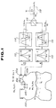
- Figure 2 shows an actual example of a circuit of the nature illustrated in block diagram form in Fig. 1. That is to say a circuit which is arranged for use with rigid vessels.
- first and second buffer circuits 121, 122 are connected to the inputs of first and second band pass filters 112, 113.
- band pass filters of the nature which enable the Q value of the same to be selectively adjusted.
- First and second amplitude detecting circuits 114, 115 are provided with smoothing circuits 114a, 115a which remove the noise peaks while the second amplitude detection circuit has an amplifier 123 connected to its output.
- a standard value generating circuit 124 includes a shunt regulator which permits the output to be adjusted to a value indicative of the value VT + V1.
- Fig. 3 shows graphically the noise spectrum which tends to occur in the fuel tank of an automotive vehicle during operation of the same. As will be appreciated, low noise levels occur in the 1 - 15 Hz and >20Hz ranges.
- the noise (I) which is caused by the heat contained in the fuel which comes back from the engine, the vibration which is applied externally to the fuel tank walls and the sloshing of the fuel within the tank (III) are such that if the magnitude of the volume change (II) induced at a given frequency by the displacement means, is A.
- This data is such as to indicate that it is possible to select frequencies in 1 - 25Hz and > 30Hz ranges.
- Figs. 5 to 8 show second to fifth embodiments of the invention, wherein speakers and microphones are utilized as a displacement device and as pressure sensors, respectively.
- the second embodiment shown in Fig 5 is such that a speaker 200 is disposed in a chamber defining structure in a manner to divide the same into first and second sub-chamber sections 201, 202.
- the upper sub-chamber 201 as seen in the drawings is fluidly communicated with the interior of the main tank by way of a conduit 204.
- An orifice 206 is disposed in the conduit 204 in order to limit the communication with the main tank 100 to the degree that changes in ambient pressure and temperature alone can be transmitted to the upper sub-chamber.
- a dynamic microphone 208 is arranged to be exposed to the interior of the upper sub-chamber 201 while a condensor type microphone 210 is arranged to be exposed to the lower sub-chamber 202.
- the lower sub-chamber 202 is open directly to the interior of the main tank 100. Accordingly, the condensor microphone 210 is thus located in a position to detect the pressure changes in the main tank.
- a dynamic microphone 208 is employed in the upper chamber 201 is that condensor type microphones tend to be sensitive to the point of becoming inoperative if exposed to the pressure changes of the nature which occur in the upper sub-chamber 201 for prolonged periods.
- the outputs of the microphones 208, 210 are fed to circuit arrangement of the nature illustrated in Fig. 1.
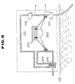
- the third embodiment shown in Fig. 6 is such as to include a perforated splash guard 212 which is arranged to enclose the open end of the lower sub-chamber.
- a perforated splash guard 212 which is arranged to enclose the open end of the lower sub-chamber.
- small diameter bores 214 are formed through the walls of the structure in a manner which permits a very limited amount of fluid communication between the interior of the upper sub-chamber and the interior of the main tank 100.
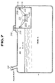
- the fourth embodiment shown in Fig. 7 is such that the speaker 200 is arranged to face vertically upward and the sub-chamber 201 which is defined thereabove is arranged to communicate with the interior of the main tank by way of a U-shaped passage 216 and a mesh screen 218.
- the provision of the mesh screen and the U-shaped passage 216 is deemed to reduce the chances of fuel splashing up into the sub-chamber 201 in which the speakers and microphones are disposed.
- the first and second sub-chambers 201 and 202 are communicated by means of an orifice passage r1 for static pressure equalization.
- a float 220 is arranged so as to block the U-shaped passage 216 in the case of large waves. Under normal circumstances this float 220 rests on top of the mesh grid 218. Moreover, in this embodiment the speaker 200 is arranged to face sideways, that is, the diaphragm is arranged vertically.
- Fig 9. is a graph which shows in terms of actual liquid content and the measured volume the remarkable linearity which is possible with the present invention.
- Figs. 10 and 11 show a technique whereby the present invention can be readily applied to very large storage vessels. As shown by partitioning off a section 300 of the tank and permitting only limited communication between the section of the tank 300 which is baffled off and the remainder of the tank 301, as long as the capacity of the section 300 is accurately known, the need to provide a large displacement means is obviated.
Landscapes
- Physics & Mathematics (AREA)
- Fluid Mechanics (AREA)
- General Physics & Mathematics (AREA)
- Measuring Fluid Pressure (AREA)
- Measurement Of Levels Of Liquids Or Fluent Solid Materials (AREA)
Claims (10)
- Dispositif de mesure du contenu (VL) d'un récipient (100), comprenant :
un moyen définissant une chambre (106) ;
un dispositif de déplacement (200) disposé dans ladite chambre pour faire varier une pression dans ladite chambre, ledit dispositif de déplacement (200) comprenant un diaphragme, ledit diaphragme divisant ladite chambre en des première (201) et deuxième (202) sous-chambres ;
des moyens formant passage (204 ; 214 ; 216) établissant une communication de fluide entre ladite chambre et l'intérieur (VT) dudit récipient (100) ;
un premier capteur de pression (110a ; 208) agencé pour produire un premier signal de sortie (A) indiquant les variations de pression dans ladite première sous-chambre (201) ;
un deuxième capteur de pression (110b ; 210) agencé pour produire un deuxième signal de sortie (B) indiquant les variations de pression dans ladite deuxième sous-chambre (202) ;
des moyens formant circuit (112, 113, 114, 115, 116, 118) pour recevoir et traîter les signaux de sortie (A ; B) desdits premier et deuxième capteurs de pression (110a, 208 ; 110b, 210) et pour produire et émettre un signal indiquant le contenu (VL) dudit récipient (100), lesdits moyens formant circuit incluant des moyens filtrants (112, 113) pour filtrer lesdits premier et deuxième signaux de sortie (A ; B),
caractérisé en ce que
ledit dispositif de déplacement (200) fait varier ladite pression à l'intérieur de ladite chambre à une seule fréquence prédéterminée ; et
lesdits moyens filtrants (112, 113) comprennent deux canaux pour filtrer respectivement lesdits premier et deuxième signaux de sortie (A, B), les deux canaux faisant passer seulement ladite fréquence unique prédéterminée. - Dispositif selon la revendication 1, caractérisé en ce que la première sous-chambre (201) est en communication de fluide avec l'intérieur (VT) dudit récipient (100) par l'intermédiaire desdits moyens de passage (204 ; 214; 216), et
ladite deuxième sous-chambre (202) est située à l'intérieur (VT) dudit récipient (100). - Dispositif selon la revendication 1 ou 2, caractérisé en ce que ledit diaphragme est amené à vibrer à ladite fréquence unique prédéterminée.
- Dispositif selon l'une des revendications 1 à 3, caractérisé en ce que lesdites première et deuxième sous-chambres (201, 202) sont en communication de fluide par l'intermédiaire d'un passage à orifice (r1).
- Dispositif selon l'une des revendications 1 à 4, caractérisé en ce que ledit moyen formant passage (216) comprend un moyen (218, 220) pour empêcher une fuite du liquide dans ladite chambre (106).
- Dispositif selon l'une des revendications 1 à 5, caractérisé en ce que le plan dudit diaphragme est agencé verticalement.
- Dispositif selon l'une des revendications 1 à 6,
caractérisé en ce que lesdits premier et deuxième capteurs de pression (110a, 208 ; 110b, 210) sont disposés prés d'un bord périphérique dudit dispositif de déplacement (200). - Dispositif selon l'une des revendications 1 à 7,
caractérisé en ce que ladite deuxième sous-chambre (202) a une extrémité ouverte qui communique d'une manière non restreinte avec l'intérieur (VT) dudit récipient (100). - Procédé de mesure du contenu (VL) d'un récipient (100) comprenant les étapes consistant à :
disposer un dispositif de déplacement (200) dans une chambre (106) qui est en communication de fluide avec l'intérieur (VT) dudit récipient (100) par un moyen formant passage (204 ; 214, 216),
diviser ladite chambre en une première (201) et une deuxième (202) sous-chambre par un diaphragme faisant partie dudit dispositif de déplacement (200) ;
exciter ledit dispositif de déplacement (200) pour faire varier la pression dans ladite chambre ;
capter la pression dans ladite première sous-chambre (201) en utilisant un premier capteur de pression (110a ; 208) et à produire un premier signal de sortie (A) indiquant la pression dans la première sous-chambre (201) ;
capter la pression dans ladite deuxième sous-chambre (202) en utilisant un deuxième capteur de pression (110b ; 210) et à produire un deuxième signal de sortie (B) indiquant la pression dans la deuxième sous-chambre (202) ; et
filtrer et traîter les premier et deuxième signaux de sortie (A ; B) et produire un signal indiquant le contenu (VL) dudit récipient (100),
caractérisé en ce que
on fait varier ladite pression dans ladite chambre à une fréquence unique prédéterminée ; et
ladite étape de filtration est excécutée par deux canaux pour filtrer respectivement lesdits premier et deuxième signaux de sortie (A, B), les deux canaux faisant passer seulement ladite fréquence unique prédéterminée. - Procédé selon la revendication 9, caractérisé en ce que la variation de la pression dans ladite chambre (106) est exécutée en faisant vibrer le diaphragme du dispositif de déplacement (200) à ladite fréquence unique prédéterminée.
Applications Claiming Priority (12)
| Application Number | Priority Date | Filing Date | Title |
|---|---|---|---|
| JP169634/88 | 1988-07-07 | ||
| JP63169633A JP2785938B2 (ja) | 1988-07-07 | 1988-07-07 | 体積測定装置 |
| JP169635/88 | 1988-07-07 | ||
| JP169633/88 | 1988-07-07 | ||
| JP16963488A JPH0219718A (ja) | 1988-07-07 | 1988-07-07 | 体積測定方法及びその装置 |
| JP16963588A JPH0219719A (ja) | 1988-07-07 | 1988-07-07 | 体積測定方法及びその装置 |
| JP2780889A JP2778971B2 (ja) | 1989-02-07 | 1989-02-07 | 体積測定方法及びその装置 |
| JP27808/89 | 1989-02-07 | ||
| JP27809/89 | 1989-02-07 | ||
| JP2780989A JPH02206724A (ja) | 1989-02-07 | 1989-02-07 | 体積測定方法及びその装置 |
| JP1989028948U JP2507655Y2 (ja) | 1989-03-14 | 1989-03-14 | 体積測定装置 |
| JP28948/89 | 1989-03-14 |
Publications (3)
| Publication Number | Publication Date |
|---|---|
| EP0350074A2 EP0350074A2 (fr) | 1990-01-10 |
| EP0350074A3 EP0350074A3 (fr) | 1992-03-25 |
| EP0350074B1 true EP0350074B1 (fr) | 1995-10-04 |
Family
ID=27549369
Family Applications (1)
| Application Number | Title | Priority Date | Filing Date |
|---|---|---|---|
| EP19890112499 Expired - Lifetime EP0350074B1 (fr) | 1988-07-07 | 1989-07-07 | Méthode et dispositif de mesure du contenu d'un récipient de stockage |
Country Status (3)
| Country | Link |
|---|---|
| EP (1) | EP0350074B1 (fr) |
| CA (1) | CA1335000C (fr) |
| DE (1) | DE68924449T2 (fr) |
Cited By (1)
| Publication number | Priority date | Publication date | Assignee | Title |
|---|---|---|---|---|
| US7946170B2 (en) | 2004-11-01 | 2011-05-24 | Yasuaki Nakamura | Residual liquid quantity detecting method |
Families Citing this family (2)
| Publication number | Priority date | Publication date | Assignee | Title |
|---|---|---|---|---|
| RU2181191C1 (ru) * | 2000-08-01 | 2002-04-10 | Открытое акционерное общество "Ракетно-космическая корпорация "Энергия" имени С.П. Королева" | Измеритель уровня жидкости |
| RU2301971C2 (ru) * | 2005-08-22 | 2007-06-27 | Михаил Сергеевич Зайков | Способ измерения уровня жидкости в баке и устройство для его осуществления |
Family Cites Families (2)
| Publication number | Priority date | Publication date | Assignee | Title |
|---|---|---|---|---|
| GB2144550B (en) * | 1983-07-01 | 1986-11-05 | John Brown Pond | Improved volume measuring system |
| US4599892A (en) * | 1984-12-04 | 1986-07-15 | Doshi Navin H | Volume measuring apparatus |
-
1989
- 1989-07-07 DE DE1989624449 patent/DE68924449T2/de not_active Expired - Fee Related
- 1989-07-07 EP EP19890112499 patent/EP0350074B1/fr not_active Expired - Lifetime
- 1989-07-07 CA CA 605094 patent/CA1335000C/fr not_active Expired - Fee Related
Cited By (1)
| Publication number | Priority date | Publication date | Assignee | Title |
|---|---|---|---|---|
| US7946170B2 (en) | 2004-11-01 | 2011-05-24 | Yasuaki Nakamura | Residual liquid quantity detecting method |
Also Published As
| Publication number | Publication date |
|---|---|
| DE68924449T2 (de) | 1996-03-07 |
| EP0350074A3 (fr) | 1992-03-25 |
| CA1335000C (fr) | 1995-03-28 |
| DE68924449D1 (de) | 1995-11-09 |
| EP0350074A2 (fr) | 1990-01-10 |
Similar Documents
| Publication | Publication Date | Title |
|---|---|---|
| US4474061A (en) | Sonic pressure volume measuring device | |
| US3237451A (en) | Volumetric measurement system | |
| US4599892A (en) | Volume measuring apparatus | |
| US4297872A (en) | Vibration type transducer | |
| US5058437A (en) | Determining the quantity yield of a compressible fluid flowing through a pressure reducing valve | |
| EP0572492B1 (fr) | Procede et appareil servant a affaiblir les vibrations acoustiques dans un milieu | |
| US5048323A (en) | Fluid metering | |
| US5531111A (en) | Structure of a volumetric measuring apparatus | |
| EP0350074B1 (fr) | Méthode et dispositif de mesure du contenu d'un récipient de stockage | |
| US4531405A (en) | Method and device for measuring the level of a fluid inside of a container | |
| US5309760A (en) | Method and apparatus for measuring the content of a storage vessel | |
| US11503412B2 (en) | Acoustic sensor and electrical circuits therefor | |
| GB2227317A (en) | Infrasonic hydrophone signal correction arrangement | |
| US3675485A (en) | Method and apparatus for measuring variations in a quantity with respect to a known reference value | |
| JP2533306B2 (ja) | 体積計 | |
| JPH06201434A (ja) | 体積検出装置 | |
| JPH06201433A (ja) | 体積検出装置 | |
| SU822389A1 (ru) | Устройство дл градуировки гидрофонов | |
| GB1366346A (en) | Fluid density gauge | |
| SU1434304A1 (ru) | Способ определени коэффициента демпфировани и устройство дл его осуществлени | |
| SU1744475A1 (ru) | Устройство дл измерени скорости газовоздушных потоков | |
| SU371435A1 (ru) | Всесоюзная ' | |
| SU849025A1 (ru) | Устройство дл испытани изделийНА ВОздЕйСТВиЕ СлучАйНыХ ВибРАций | |
| SU1619080A1 (ru) | Устройство дл измерени давлени | |
| KR840001177B1 (ko) | 압력계 |
Legal Events
| Date | Code | Title | Description |
|---|---|---|---|
| PUAI | Public reference made under article 153(3) epc to a published international application that has entered the european phase |
Free format text: ORIGINAL CODE: 0009012 |
|
| 17P | Request for examination filed |
Effective date: 19890707 |
|
| AK | Designated contracting states |
Kind code of ref document: A2 Designated state(s): DE FR GB SE |
|
| PUAL | Search report despatched |
Free format text: ORIGINAL CODE: 0009013 |
|
| AK | Designated contracting states |
Kind code of ref document: A3 Designated state(s): DE FR GB SE |
|
| 17Q | First examination report despatched |
Effective date: 19931217 |
|
| RAP1 | Party data changed (applicant data changed or rights of an application transferred) |
Owner name: KANSEI CORPORATION |
|
| GRAA | (expected) grant |
Free format text: ORIGINAL CODE: 0009210 |
|
| AK | Designated contracting states |
Kind code of ref document: B1 Designated state(s): DE GB SE |
|
| REF | Corresponds to: |
Ref document number: 68924449 Country of ref document: DE Date of ref document: 19951109 |
|
| EN | Fr: translation not filed | ||
| PLBE | No opposition filed within time limit |
Free format text: ORIGINAL CODE: 0009261 |
|
| STAA | Information on the status of an ep patent application or granted ep patent |
Free format text: STATUS: NO OPPOSITION FILED WITHIN TIME LIMIT |
|
| 26N | No opposition filed | ||
| PGFP | Annual fee paid to national office [announced via postgrant information from national office to epo] |
Ref country code: GB Payment date: 19990628 Year of fee payment: 11 |
|
| PGFP | Annual fee paid to national office [announced via postgrant information from national office to epo] |
Ref country code: SE Payment date: 19990726 Year of fee payment: 11 |
|
| PGFP | Annual fee paid to national office [announced via postgrant information from national office to epo] |
Ref country code: DE Payment date: 19990830 Year of fee payment: 11 |
|
| PG25 | Lapsed in a contracting state [announced via postgrant information from national office to epo] |
Ref country code: GB Free format text: LAPSE BECAUSE OF NON-PAYMENT OF DUE FEES Effective date: 20000707 |
|
| PG25 | Lapsed in a contracting state [announced via postgrant information from national office to epo] |
Ref country code: SE Free format text: LAPSE BECAUSE OF NON-PAYMENT OF DUE FEES Effective date: 20000708 |
|
| GBPC | Gb: european patent ceased through non-payment of renewal fee |
Effective date: 20000707 |
|
| EUG | Se: european patent has lapsed |
Ref document number: 89112499.2 |
|
| PG25 | Lapsed in a contracting state [announced via postgrant information from national office to epo] |
Ref country code: DE Free format text: LAPSE BECAUSE OF NON-PAYMENT OF DUE FEES Effective date: 20010501 |