EP0352487A1 - An automatic, self-propelled cleaner for swimming pools - Google Patents
An automatic, self-propelled cleaner for swimming pools Download PDFInfo
- Publication number
- EP0352487A1 EP0352487A1 EP89111594A EP89111594A EP0352487A1 EP 0352487 A1 EP0352487 A1 EP 0352487A1 EP 89111594 A EP89111594 A EP 89111594A EP 89111594 A EP89111594 A EP 89111594A EP 0352487 A1 EP0352487 A1 EP 0352487A1
- Authority
- EP
- European Patent Office
- Prior art keywords
- cleaner
- cam
- wheel
- driven
- lobes
- Prior art date
- Legal status (The legal status is an assumption and is not a legal conclusion. Google has not performed a legal analysis and makes no representation as to the accuracy of the status listed.)
- Withdrawn
Links
- 230000009182 swimming Effects 0.000 title claims description 11
- 230000033001 locomotion Effects 0.000 claims abstract description 20
- 230000008901 benefit Effects 0.000 description 4
- XLYOFNOQVPJJNP-UHFFFAOYSA-N water Substances O XLYOFNOQVPJJNP-UHFFFAOYSA-N 0.000 description 4
- 238000004140 cleaning Methods 0.000 description 2
- 238000010276 construction Methods 0.000 description 2
- 230000009194 climbing Effects 0.000 description 1
- 230000001419 dependent effect Effects 0.000 description 1
- 238000001914 filtration Methods 0.000 description 1
- 230000001788 irregular Effects 0.000 description 1
- 230000013011 mating Effects 0.000 description 1
Images

Classifications
-
- E—FIXED CONSTRUCTIONS
- E04—BUILDING
- E04H—BUILDINGS OR LIKE STRUCTURES FOR PARTICULAR PURPOSES; SWIMMING OR SPLASH BATHS OR POOLS; MASTS; FENCING; TENTS OR CANOPIES, IN GENERAL
- E04H4/00—Swimming or splash baths or pools
- E04H4/14—Parts, details or accessories not otherwise provided for
- E04H4/16—Parts, details or accessories not otherwise provided for specially adapted for cleaning
- E04H4/1654—Self-propelled cleaners
Definitions
- This invention relates to an automatic, self-propelled swimming pool cleaner.
- Cleaners of this kind fall basically into two major classes: electrically operated cleaners and hydraulically operated ones.
- cleaners classes A common requirement to both cleaners classes is that they should allow of changes in their travel paths across the pool bottom and side walls such that the whole pool surface can be cleaned.
- the cleaner is to readily go over such obstacles as edges, corners, fittings, and any other surface discontinuities met on the pool surfaces being cleaned.
- Electric cleaners benefit, in comparison with hydraulic cleaners, from more convenient handling of their directional control because changes in direction and deviations from a set travel path can be programmed through electric signals sent to the cleaner drive motors.
- their construction is more complex than that of hydraulic cleaners, and watertight compartments must be arranged for their electric components.
- the problem that underlies this invention is to provide an automatic cleaner for swimming pools which is so designed and constructed as to combine all the advantages of hydraulically operated cleaners, while affording a thorough cleaning action all over the submerged surfaces of a swimming pool, and to be drivable over edges and corners and along irregular paths.
- the invention is also directed to provide a cleaner having a directional control system which can be tailored to suit specific demands, by the user himself.
- an automatic, self-propelled cleaner for swimming pools being characterized in that it comprises a hydraulic turbine motor for one way driving two oppositely located wheel locomotion members and at least one cam driven by the motor and associated with one of said locomotion members to temporarily raise it while the other locomotion member is held in engagement, thereby the travel direction of the cleaner can be changed.
- the cam would be keyed releasably to a shaft driven by said motor externally of the body of said cleaner.
- An automatic, self-propelled swimming pool cleaner is generally indicated at 1 throughout the drawing views.
- the cleaner 1 comprises a body 2 which is closed at the top by a detachable cover 3 and accommodates a hydraulic turbine motor 4 on its interior.
- the bottom wall 2a of the body 2 is provided with a suction fitting 5 for the motor 4.
- a manifold 6 extends across the cover 3 to direct the discharge flow passed through the motor 4.
- Fitted releasably to the manifold 6 is a flexible pipe, not shown , through which the cleaner 1 is connected to the strainer system of a swimming pool at the so-called skimmer fitting.
- the motor 4 drives, via a worm reduction gear 7 and a gear train 8, first and second shafts, respectively indicated at 9 and 10.
- first shaft 9 Keyed to the opposed ends of the first shaft 9 are two drive wheels 11a,b and two corresponding wheels 12a,b are keyed to the ends of an idler shaft 13 borne frontally on the body 2. All the wheels have a raised circumferential rib 50 formed at a substantially central location thereon.
- an elastic track 14 e.g. made of rubber, which is formed with a plurality of flexible outwardly projecting lugs 15 and through-going slots 16.
- the slots 16 are aligned along the central portion of the track 14 to the ribs 50, thereby the track is weakened locally and held centered on the wheels 11-12,a,b.
- a cam Keyed to at least one axial end, preferably both ends, of the shaft 10 is a cam having multiple cam lobes 18a,b, c which may have different camming profiles from one another.
- the cam 18 is held releasably on the shaft 10 by a thumbscrew 19, is made rotatively rigid with the shaft 10, and is accessible from the body 2 outside for quick replacement with no further disassembling of the cleaner 1.
- a brush 20 is mounted in a tiltable manner on the front portion of the body 2.
- the brush 20 is provided with an axial shaft 21 having its ends connected to the idler shaft 13 by connecting rods 22.
- Said brush 20 is driven rotatively via a gear train 23 which connects the shaft 21 to the shaft 13 and, through the latter, to one of the wheels 12a,b.
- This cleaner 1 operates as follows.
- the reduction gear 7 rotatively drives the shaft 9 directly, and consequently, the wheels 11a,b; through the gear train 8, the hsaft 10 and the cams 18 keyed thereto are also rotated at a reduced speed relatively to the shaft 9.
- the cam lobes 18a,b,c will sequentially contact the pool surface being cleaned and raise the wheel locomotion member located on the cam 18 side off said surface for a time duration which is dependent on the radial dimension of the lobe 18a,b,c, and its shape, as well as on the rotational speed of the cam 18.
- the cleaner 1 becomes restrained at the side where a cam lobe bears on the surface being cleaned, whereas the opposite locomotion member, being held in contact with said surface, is still driving forward, thereby the cleaner will be forced into a pivotal movement about the lobe of the cam 18.
- This pivotal movement is further enhanced by the opposite rotation of the cam 18 relatively to the direction of rotation of the wheels 11-12,a,b and by the flexibility of the lugs 15, which will deform elastically during the cleaner 1 pivoting to counteract possible sideward forces tending to disentangle the tracks 14.
- the suction applied through the fitting 5 is assisted by the mechanical action of the brush 20 which effectively removes foul matter clinging to the pool surfaces.
- the shaft 10 would have, at least in the cam 30 keying region, a polygonal cross-section shape, e.g. a hexagonal shape, wherewith the three lobes are engaged by means of mating holes 31 having an identical cross-sectional shape.
- a polygonal cross-section shape e.g. a hexagonal shape
- the vacuum generated beneath the body 2 by the suction flow through the fitting 5 is adequate to ensure adhesion of the cleaner 1 not only to the pool bottom but also to the upright (or in all cases, steep) side walls of the same.
- this modified embodiment of the cam is generally indicated at 40 and has a single cam lobe 40a, it being understood that the cam 40 may include multiple angularly spaced lobes similarly to the cam 30.
- the free end of the lobe 40a carries a small wheel 41 which has a pinion gear 42 formed integrally therewith.
- the pinion gear 42 is in mesh-engagement with a gear 43 made rigid with the body 2 such that, as the lobe 40a is rotated, the wheel 41 will be rotated about its own axis in the same direction as the cam 40.
- a cam not shown, which has, on the free end of its lobes, a small wheel allowed to turn freely in the opposite direction of rotation from the forward travel direction of the cleaner 1 but restrained from rotation in the other direction, such as by providing it with a conventional freewheel mechanism.
- one side of the cleaner 1 will be pulled downwards (arrow F5) by the tractive action of the wheel 41, or by its own weight with the wheel freely rotating if equipped with a freewheel mechanism, thereby raising its corresponding locomotion member off the wall surface.
- the other locomotion member will remain submerged and will be able to drag the cleaner 1 in the direction of the arrow F6.
- the wheels 11a,b On the cleaner 1 arriving at the bottom of an upright wall to start climbing it, the wheels 11a,b will have a different instantaneous rotational speed from the rotational speed of the wheels 12a,b.
- This rotational speed differential is accommodated by the elasticity of the tracks 14, also by virtue of the slots 16 provided and of the resiliency of the lugs 15.
- the cleaner of this invention affords a number of advantages over prior cleaners.
- track locomotion members enable it to get over bumps and surface irregularities of the swimming pool, while making it easier for the cleaner 1 to negotiate blind spots at corners or along twisting travel paths.
- the program that controls the cleaner changes of direction can be varied at will by the operator using very simple means (it is sufficient that the cam be replaced or that its lobes be given different angular settings) and without involving any disassembling of cleaner parts.
- a range of directional control programs can be manufactured at very low costs on account of the inherently simple construction of the cams.
Landscapes
- Engineering & Computer Science (AREA)
- Architecture (AREA)
- Civil Engineering (AREA)
- Structural Engineering (AREA)
- Electric Suction Cleaners (AREA)
- Cleaning In General (AREA)
- Brushes (AREA)
Abstract
An automatic, self-propelled cleaner (1) comprises a hydraulic turbine motor (4) for one-way driving two oppositely located wheel locomotion members and at least one cam (18) driven by the motor (4) and associated with one (11a,12a) of the wheel locomotion members to temporarily raise it while the other (11b,12b) of the wheel locomotion members is held engaged, thereby the travel direction of the cleaner can be changed.
Description
- This invention relates to an automatic, self-propelled swimming pool cleaner.
- Cleaners of this kind fall basically into two major classes: electrically operated cleaners and hydraulically operated ones.
- A common requirement to both cleaners classes is that they should allow of changes in their travel paths across the pool bottom and side walls such that the whole pool surface can be cleaned.
- In addition, the cleaner is to readily go over such obstacles as edges, corners, fittings, and any other surface discontinuities met on the pool surfaces being cleaned.
- Examples of hydraulically operated cleaners are described in US Patent No. 4,560,418 and German Patent No. 2612043. Examples of electrically operated cleaners are described in European Patent No. 257006 and French Patant Applicaation No. 2584442.
- Electric cleaners benefit, in comparison with hydraulic cleaners, from more convenient handling of their directional control because changes in direction and deviations from a set travel path can be programmed through electric signals sent to the cleaner drive motors. On the other hand, their construction is more complex than that of hydraulic cleaners, and watertight compartments must be arranged for their electric components.
- Irrespective of how easily the directional control of electric cleaners can be provided, if the program that handles such control cannot be altered by the user, it may occur that a present control routine fails to fit different pool designs.
- For these and other reasons, fully hydraulically operated cleaners have met widespread commercial acceptance despite their lower flexibility.
- Among the reasons for such acceptance is that the foul matter removed by the cleaner is at once taken away from the pool and collected in the main filtering system, which affords increased range for the cleaner and fully safe operation thereof, as well as described cost.
- The problem that underlies this invention is to provide an automatic cleaner for swimming pools which is so designed and constructed as to combine all the advantages of hydraulically operated cleaners, while affording a thorough cleaning action all over the submerged surfaces of a swimming pool, and to be drivable over edges and corners and along irregular paths.
- The invention is also directed to provide a cleaner having a directional control system which can be tailored to suit specific demands, by the user himself.
- The above problem is solved, according to the invention, by an automatic, self-propelled cleaner for swimming pools being characterized in that it comprises a hydraulic turbine motor for one way driving two oppositely located wheel locomotion members and at least one cam driven by the motor and associated with one of said locomotion members to temporarily raise it while the other locomotion member is held in engagement, thereby the travel direction of the cleaner can be changed.
- Advantageously, the cam would be keyed releasably to a shaft driven by said motor externally of the body of said cleaner.
- The features and advantages of this invention will become more clearly apparent from the following detailed description of a preferred, but not exclusive, embodiment thereof, to be raken by way of illustration and not of limitation in conjunction with the accompanying drawing, where:
- Figure 1 is a perspective view from above of a cleaner embodying this invention;
- Figure 2 is a side elevation view of the cleaner shown in Figure 1;
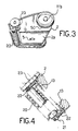
- Figures 3 and 4 are a perspective bottom view and longitudinal section view, respectively, of a detail of the cleaner shown in the preceding Figures;
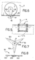
- Figure 5 illustrates in schematic form a particular condition of operation of this cleaner;
- Figure 6 shows a first embodiment of a detail of the cleaner according to the preceding Figures; and
- Figures 7 and 8 are side elevation and top plan views, respectively, of a second embodiment of the detail shown in Figure 6.
- An automatic, self-propelled swimming pool cleaner is generally indicated at 1 throughout the drawing views.
- The
cleaner 1 comprises abody 2 which is closed at the top by a detachable cover 3 and accommodates a hydraulic turbine motor 4 on its interior. - The
bottom wall 2a of thebody 2 is provided with a suction fitting 5 for the motor 4. Amanifold 6 extends across the cover 3 to direct the discharge flow passed through the motor 4. - Fitted releasably to the
manifold 6 is a flexible pipe, not shown , through which thecleaner 1 is connected to the strainer system of a swimming pool at the so-called skimmer fitting. - The motor 4 drives, via a
worm reduction gear 7 and a gear train 8, first and second shafts, respectively indicated at 9 and 10. - Keyed to the opposed ends of the
first shaft 9 are twodrive wheels 11a,b and twocorresponding wheels 12a,b are keyed to the ends of anidler shaft 13 borne frontally on thebody 2. All the wheels have a raisedcircumferential rib 50 formed at a substantially central location thereon. - Stretched between each
wheel pair elastic track 14, e.g. made of rubber, which is formed with a plurality of flexible outwardly projectinglugs 15 and through-going slots 16. Theslots 16 are aligned along the central portion of thetrack 14 to theribs 50, thereby the track is weakened locally and held centered on the wheels 11-12,a,b. - Reference will be made herein below to the combination of each
wheel pair respective track 14 as the "wheel locomotion member". - Keyed to at least one axial end, preferably both ends, of the
shaft 10 is a cam havingmultiple cam lobes 18a,b, c which may have different camming profiles from one another. - The provision of two cams prevents kinking of the flexible pipe connected to the
manifold 6. However, a single cam would still ensure operability of thecleaner 1, as explained herein below. - The
cam 18 is held releasably on theshaft 10 by athumbscrew 19, is made rotatively rigid with theshaft 10, and is accessible from thebody 2 outside for quick replacement with no further disassembling of thecleaner 1. - A
brush 20 is mounted in a tiltable manner on the front portion of thebody 2. For this purpose, thebrush 20 is provided with anaxial shaft 21 having its ends connected to theidler shaft 13 by connectingrods 22. - Said
brush 20 is driven rotatively via agear train 23 which connects theshaft 21 to theshaft 13 and, through the latter, to one of thewheels 12a,b. - This
cleaner 1 operates as follows. - By connecting the
manifold 6 through the aforesaid flexible pipe to the skimmer fitting of the swimming pool, a flow of water is caused to be drawn through the fitting 5 and the hydraulic turbine motor 4. - The flow of water thus drawn in rotates the turbine of the motor 4, and hence the
worm reduction gear 7 and gear train 8. - The
reduction gear 7 rotatively drives theshaft 9 directly, and consequently, thewheels 11a,b; through the gear train 8, thehsaft 10 and thecams 18 keyed thereto are also rotated at a reduced speed relatively to theshaft 9. - The direction of rotation of the
cam 18, as indicated by an arrow F1 in Figure 2, is opposite from the direction of rotation of thewheels 11a,b, as indicated by an arrow F2 in the same Figure. - During the rotation of the
cam 18, thecam lobes 18a,b,c will sequentially contact the pool surface being cleaned and raise the wheel locomotion member located on thecam 18 side off said surface for a time duration which is dependent on the radial dimension of thelobe 18a,b,c, and its shape, as well as on the rotational speed of thecam 18. - Thus, the
cleaner 1 becomes restrained at the side where a cam lobe bears on the surface being cleaned, whereas the opposite locomotion member, being held in contact with said surface, is still driving forward, thereby the cleaner will be forced into a pivotal movement about the lobe of thecam 18. This pivotal movement is further enhanced by the opposite rotation of thecam 18 relatively to the direction of rotation of the wheels 11-12,a,b and by the flexibility of thelugs 15, which will deform elastically during thecleaner 1 pivoting to counteract possible sideward forces tending to disentangle thetracks 14. - The suction applied through the fitting 5 is assisted by the mechanical action of the
brush 20 which effectively removes foul matter clinging to the pool surfaces. - The frequency of the changes in direction of the
cleaner 1 and the extent of the angular travel path deviations can be readily varied by suitably altering the profile of thecam 18. For this purpose, shown in Figures 7 and 8 is an assembly cam, generally indicated at 30, which includes three stackedlobes 30a,b,c into a pack-like configuration which can be locked on theshaft 10 by means of thethumbscrew 19. - Preferably, the
shaft 10 would have, at least in thecam 30 keying region, a polygonal cross-section shape, e.g. a hexagonal shape, wherewith the three lobes are engaged by means ofmating holes 31 having an identical cross-sectional shape. - The vacuum generated beneath the
body 2 by the suction flow through the fitting 5 is adequate to ensure adhesion of thecleaner 1 not only to the pool bottom but also to the upright (or in all cases, steep) side walls of the same. - In cleaning such upright side walls, it may occur that the machine reaches, while in a vertical trim condition, the water free surface and cones out of the water by a few centimeters, until the buoyancy and drive forces equal the weight of the
cleaner 1. Under that condition, the adhesion of the locomotion members to the wall surface of the swimming pool would be insufficient to permit of the normal pivoting of the machine (Figure 5), and to obviate this brawback, a different cam design has been provided, as shown in Figure 6. - In Figure 6, this modified embodiment of the cam is generally indicated at 40 and has a
single cam lobe 40a, it being understood that thecam 40 may include multiple angularly spaced lobes similarly to thecam 30. - The free end of the
lobe 40a carries asmall wheel 41 which has apinion gear 42 formed integrally therewith. Thepinion gear 42 is in mesh-engagement with agear 43 made rigid with thebody 2 such that, as thelobe 40a is rotated, thewheel 41 will be rotated about its own axis in the same direction as thecam 40. - Alternatively, a cam, not shown, may be provided which has, on the free end of its lobes, a small wheel allowed to turn freely in the opposite direction of rotation from the forward travel direction of the
cleaner 1 but restrained from rotation in the other direction, such as by providing it with a conventional freewheel mechanism. - Thus, with the
cleaner 1 in the stalled condition shown in Figure 5, and thecam 40 engaging a side wall of the pool, one side of thecleaner 1 will be pulled downwards (arrow F5) by the tractive action of thewheel 41, or by its own weight with the wheel freely rotating if equipped with a freewheel mechanism, thereby raising its corresponding locomotion member off the wall surface. The other locomotion member will remain submerged and will be able to drag thecleaner 1 in the direction of the arrow F6. - On the
cleaner 1 arriving at the bottom of an upright wall to start climbing it, thewheels 11a,b will have a different instantaneous rotational speed from the rotational speed of thewheels 12a,b. This rotational speed differential is accommodated by the elasticity of thetracks 14, also by virtue of theslots 16 provided and of the resiliency of thelugs 15. - The cleaner of this invention affords a number of advantages over prior cleaners.
- First of all, being powered throughout by a hydraulic turbine, it requires no electrical hook-ups and watertight compartments, so that it will be free of any relevant constructional complications.
- Further, the track locomotion members enable it to get over bumps and surface irregularities of the swimming pool, while making it easier for the cleaner 1 to negotiate blind spots at corners or along twisting travel paths.
- In addition, the program that controls the cleaner changes of direction can be varied at will by the operator using very simple means (it is sufficient that the cam be replaced or that its lobes be given different angular settings) and without involving any disassembling of cleaner parts.
- A range of directional control programs can be manufactured at very low costs on account of the inherently simple construction of the cams.
Claims (14)
1. An automatic, self-propelled swimming pool cleaner (1), characterized in that it comprises a hydraulic turbine motor (4) for one-way driving two oppositely located wheel locomotion members (11a,12a; 11b,12b) and at least one cam (18) driven by the motor (4) and associated with one (11a,12a) of said locomotion members to temporarily raise it while the other locomotion member (11b,12b) is held in engagement.
2. A cleaner (1) according to Claim 1, characterized in that said cam (18) is keyed releasably to a shaft (10) driven by said motor (4).
3. A cleaner (1) according to either Claim 1 or 2, characterized in that said cam (18) is rotated contrariwise with respect to the driving direction of the wheels (11a,12a; 11b,12b) of said locomotion members.
4. A cleaner (1) according to one or more of the preceding claims, characterized in that said cam (18) comprises a plurality of lobes (18a,18b,18c).
5. A cleaner (1) according to Claim 4, characterized in that the lobes (18,18b,18c) of said cam (18) are structurally independent of and angularly shiftable relatively to one another in their keyed engagement with said driven shaft (10).
6. A cleaner (1) according to either Claim 4 or 5, characterized in that said lobes (18a,18b,18c) have different shapes from one another.
7. A cleaner (1) according to one or more of the preceding claims, characterized in that the free end of said lobes (18a,18b,18c) carries a small wheel (41) arranged to turn concurrently with said cam.
8. A cleaner (1) according to Claim 7, characterized in that said small wheel (41) is power driven.
9. A cleaner (1) according to Claim 8, characterized in that said small wheel (41) is integral with a pinion gear (42) in mesh-engagement with a gear (43) affixed to a body (2) of said cleaner (1).
10. A cleaner (1) according to one or more of the preceding claims, characterized in that each of said wheel locomotion members comprises at least one drive wheel (11a,11b) and driven wheel (12a,12b) and a track (14) trained around said drive and driven wheels.
11. A cleaner (1) according to Claim 10, characterized in that said track (14) is deformable elastically.
12. A cleaner (1) according to Claim 11, characterized in that said track (14) is provided with a plurality of elastically deformable outward lugs (15).
13. A cleaner (1) according to Claims 10 to 12, characterized in that said track (14) is formed with a plurality of through-going slots (16).
14. A cleaner (1) according to one or more of the preceding claims, characterized in that it comprises a power driven brush (20) mounted in a tiltable manner on a body (2) of said cleaner (1).
Applications Claiming Priority (2)
| Application Number | Priority Date | Filing Date | Title |
|---|---|---|---|
| IT2113088 | 1988-06-28 | ||
| IT21130/88A IT1217945B (en) | 1988-06-28 | 1988-06-28 | AUTOMATIC SELF-PROPELLED CLEANER FOR SWIMMING POOLS |
Publications (1)
| Publication Number | Publication Date |
|---|---|
| EP0352487A1 true EP0352487A1 (en) | 1990-01-31 |
Family
ID=11177190
Family Applications (1)
| Application Number | Title | Priority Date | Filing Date |
|---|---|---|---|
| EP89111594A Withdrawn EP0352487A1 (en) | 1988-06-28 | 1989-06-26 | An automatic, self-propelled cleaner for swimming pools |
Country Status (5)
| Country | Link |
|---|---|
| US (1) | US5001800A (en) |
| EP (1) | EP0352487A1 (en) |
| AU (1) | AU609622B2 (en) |
| IT (1) | IT1217945B (en) |
| ZA (1) | ZA894904B (en) |
Cited By (17)
| Publication number | Priority date | Publication date | Assignee | Title |
|---|---|---|---|---|
| EP0468876A1 (en) * | 1990-07-25 | 1992-01-29 | Michael John Chandler | Hydraulic sweeper for swimming pool and similar |
| EP0622506A1 (en) * | 1993-04-01 | 1994-11-02 | Dennis Andrew Raubenheimer | Suction cleaner for submerged surfaces |
| WO1995002103A1 (en) * | 1993-07-09 | 1995-01-19 | Arneson Products, Inc. | Automatic pool cleaning apparatus |
| EP1947265A3 (en) * | 2005-08-04 | 2008-07-30 | Maytronics Ltd. | Pool cleaning robot |
| EP1925593A3 (en) * | 2006-11-21 | 2010-04-14 | Crystal Lagoons Corporation LLC | Process to obtain (implement and maintain) water bodies larger than 15,000 m3 for recreational use with color, transparency and cleanness characteristics similar to swimming pools or tropical seas at low cost |
| WO2010055259A1 (en) * | 2008-11-14 | 2010-05-20 | P.M.P.S. Technologies | Motorised robot for cleaning swimming pools or the like, which operates when submerged in a fluid |
| US8454838B2 (en) | 2011-03-30 | 2013-06-04 | Crystal Lagoons (Curacao) B.V. | Method and system for the sustainable cooling of industrial processes |
| US8465651B2 (en) | 2011-03-30 | 2013-06-18 | Crystal Lagoons (Curacao) B.V. | Sustainable method and system for treating water bodies affected by bacteria and microalgae at low cost |
| US8518269B2 (en) | 2011-03-30 | 2013-08-27 | Crystal Lagoons (Curacao) B.V. | Method and system for treating water used for industrial purposes |
| US8753520B1 (en) | 2012-12-19 | 2014-06-17 | Crystal Lagoons (Curacao), B.V. | Localized disinfection system for large water bodies |
| EP2584118A3 (en) * | 2011-10-18 | 2015-05-27 | Aquatron Robotic Technology Ltd. | Robot for cleaning swimming pools |
| US9080342B2 (en) | 2008-12-24 | 2015-07-14 | Crystal Lagoons (Curacao) B.V. | Suctioning device for travelling a tank bottom |
| WO2016020862A1 (en) * | 2014-08-05 | 2016-02-11 | Herman Stoltz | Automatic pool cleaner gear mechanism |
| US9470008B2 (en) | 2013-12-12 | 2016-10-18 | Crystal Lagoons (Curacao) B.V. | System and method for maintaining water quality in large water bodies |
| US9920498B2 (en) | 2013-11-05 | 2018-03-20 | Crystal Lagoons (Curacao) B.V. | Floating lake system and methods of treating water within a floating lake |
| US9957693B2 (en) | 2014-11-12 | 2018-05-01 | Crystal Lagoons (Curacao) B.V. | Suctioning device for large artificial water bodies |
| US11453603B2 (en) | 2019-06-28 | 2022-09-27 | Crystal Lagoons Technologies, Inc. | Low cost and sanitary efficient method that creates two different treatment zones in large water bodies to facilitate direct contact recreational activities |
Families Citing this family (67)
| Publication number | Priority date | Publication date | Assignee | Title |
|---|---|---|---|---|
| USD336695S (en) | 1990-01-06 | 1993-06-22 | Seikosha Co., Ltd. | Desk top cleaner |
| US5138741A (en) * | 1990-06-13 | 1992-08-18 | Allen Henry W | Remote controlled sludge removal system |
| US5269041A (en) * | 1990-06-13 | 1993-12-14 | Allen Henry W | Remote controlled sludge removal apparatus |
| US5335395A (en) * | 1990-06-13 | 1994-08-09 | Allen Henry W | Remote controlled sludge removal apparatus |
| US5799351A (en) * | 1990-09-21 | 1998-09-01 | Rief; Dieter J. | Swimming pool cleaner with vibratory power |
| US5379473A (en) * | 1990-09-21 | 1995-01-10 | Sta-Rite Industries, Inc. | Automatic swimming pool cleaner |
| US5197158A (en) * | 1992-04-07 | 1993-03-30 | Philip L. Leslie | Swimming pool cleaner |
| US5337434A (en) * | 1993-04-12 | 1994-08-16 | Aqua Products, Inc. | Directional control means for robotic swimming pool cleaners |
| US5469596A (en) * | 1993-11-03 | 1995-11-28 | Sta-Rite Industries, Inc. | Dual-use and manual pool cleaning apparatus |
| US5893188A (en) * | 1996-10-31 | 1999-04-13 | Letro Products, Inc. | Automatic swimming pool cleaner |
| US5933899A (en) * | 1996-10-31 | 1999-08-10 | Letro Products, Inc. | Low pressure automatic swimming pool cleaner |
| USD421512S (en) * | 1996-11-21 | 2000-03-07 | Letro Products, Inc. | Automatic swimming pool cleaner |
| US6119293A (en) * | 1997-07-11 | 2000-09-19 | Moyra A. Phillipson Family Trust | Submerged surface pool cleaning device |
| US6751822B2 (en) | 1997-07-11 | 2004-06-22 | Pavelssebor Family Trust | Submerged surface pool cleaning device |
| US6099091A (en) * | 1998-01-20 | 2000-08-08 | Letro Products, Inc. | Traction enhanced wheel apparatus |
| US6094764A (en) * | 1998-06-04 | 2000-08-01 | Polaris Pool Systems, Inc. | Suction powered pool cleaner |
| US6099658A (en) * | 1998-09-29 | 2000-08-08 | Aqua Products Inc. | Apparatus and method of operation for high-speed swimming pool cleaner |
| ES2250146T3 (en) * | 2000-05-26 | 2006-04-16 | Poolvergnuegen | AUTOMATIC SWIMMING POOL CLEANER WITH FOUR WHEEL TRACTION. |
| US6854148B1 (en) | 2000-05-26 | 2005-02-15 | Poolvernguegen | Four-wheel-drive automatic swimming pool cleaner |
| USD443737S1 (en) | 2000-07-24 | 2001-06-12 | Dieter J. Rief | Four wheel pool cleaner |
| ATE452260T1 (en) * | 2001-07-03 | 2010-01-15 | Pentair Pool Products Inc | BASE FOR AN AUTOMATIC SWIMMING POOL CLEANING DEVICE |
| USD471330S1 (en) | 2002-06-25 | 2003-03-04 | Letro Products, Inc. | Automatic swimming pool cleaner |
| IL158112A0 (en) * | 2003-09-25 | 2004-03-28 | Aquaproducts Inc | Apparatus for improved subaqueous stability |
| ITPD20050028A1 (en) | 2005-02-08 | 2006-08-09 | Vittorio Pareti | POOL CLEANING MACHINE |
| US20090300862A1 (en) * | 2005-11-01 | 2009-12-10 | Integrated Pool Products (Pty) Ltd. | A swimming pool cleaner |
| US8117704B2 (en) * | 2005-11-01 | 2012-02-21 | Integrated Pool Products (Pty) Ltd | Swimming pool cleaner |
| US20080099409A1 (en) * | 2006-10-26 | 2008-05-01 | Aquatron Robotic Systems Ltd. | Swimming pool robot |
| US8505143B2 (en) | 2006-11-28 | 2013-08-13 | Gedaliahu Finezilber | Programmable steerable robot particularly useful for cleaning swimming pools |
| USD575915S1 (en) * | 2006-11-28 | 2008-08-26 | Integrated Pool Products (Pty) | Swimming pool cleaner |
| US20080125943A1 (en) * | 2006-11-28 | 2008-05-29 | Gedaliahu Finezilber | Programmable steerable robot particularly useful for cleaning swimming pools |
| CN101280634B (en) * | 2007-04-03 | 2012-01-25 | 卓景顾问有限公司 | Drum of a pool cleaning machine |
| IL199274A (en) * | 2008-06-12 | 2015-09-24 | Maytronics Ltd | Pool cleaning robot |
| CA127298S (en) * | 2008-06-23 | 2009-03-30 | Zodiac Pool Care Europe | Swimming pool cleaner robot |
| US8424142B2 (en) * | 2009-06-04 | 2013-04-23 | Maytronics Ltd. | Pool cleaning robot |
| US9593502B2 (en) | 2009-10-19 | 2017-03-14 | Hayward Industries, Inc. | Swimming pool cleaner |
| FR2961838B1 (en) * | 2010-06-25 | 2012-07-27 | Zodiac Pool Care Europe | AUTOMOTIVE APPARATUS IMMERED SURFACE CLEANER |
| WO2012001471A2 (en) * | 2010-06-28 | 2012-01-05 | Zodiac Pool Care Europe | Automatic pool cleaners and components thereof |
| US8990990B2 (en) | 2011-10-03 | 2015-03-31 | Pentair Water Pool And Spa, Inc. | Pool cleaner with hydraulic timer assembly |
| USD684738S1 (en) * | 2011-10-03 | 2013-06-18 | Pentair Water Pool And Spa, Inc. | Pool cleaner |
| US8956533B2 (en) | 2011-10-03 | 2015-02-17 | Pentair Water Pool And Spa, Inc. | Pool cleaner with multi-stage venturi vacuum assembly |
| US9119463B2 (en) | 2011-10-03 | 2015-09-01 | Pentair Water Pool & Spa, Inc. | Pool cleaner with detachable scrubber assembly |
| US10036175B2 (en) | 2012-10-30 | 2018-07-31 | Pavel Sebor | Turbine-driven swimming pool cleaning apparatus and method |
| US20140137343A1 (en) * | 2012-11-20 | 2014-05-22 | Aqua Products, Inc. | Pool or tank cleaning vehicle with a powered brush |
| CA2905794C (en) | 2013-03-11 | 2018-02-27 | Pentair Water Pool And Spa, Inc. | Two-wheel actuator steering system and method for pool cleaner |
| EP2971410A4 (en) | 2013-03-13 | 2017-03-22 | Pentair Water Pool and Spa, Inc. | Alternating paddle mechanism for pool cleaner |
| EP2971411A4 (en) | 2013-03-13 | 2017-04-19 | Pentair Water Pool and Spa, Inc. | Double paddle mechanism for pool cleaner |
| EP2967268A1 (en) | 2013-03-14 | 2016-01-20 | Hayward Industries, Inc. | Pool cleaner with articulated cleaning members |
| US9677294B2 (en) | 2013-03-15 | 2017-06-13 | Hayward Industries, Inc. | Pool cleaning device with wheel drive assemblies |
| USD808095S1 (en) * | 2013-09-04 | 2018-01-16 | Pavel Sebor | Swimming pool cleaner |
| USD787761S1 (en) | 2014-11-07 | 2017-05-23 | Hayward Industries, Inc. | Pool cleaner |
| USD787760S1 (en) | 2014-11-07 | 2017-05-23 | Hayward Industries, Inc. | Pool cleaner |
| USD789003S1 (en) | 2014-11-07 | 2017-06-06 | Hayward Industries, Inc. | Pool cleaner |
| USD789624S1 (en) | 2014-11-07 | 2017-06-13 | Hayward Industries, Inc. | Pool cleaner |
| EP3250327B1 (en) | 2015-01-26 | 2022-09-28 | Hayward Industries, Inc. | Swimming pool cleaner with hydrocyclonic particle separator and/or six-roller drive system |
| US9885196B2 (en) | 2015-01-26 | 2018-02-06 | Hayward Industries, Inc. | Pool cleaner power coupling |
| US9976271B2 (en) | 2015-08-18 | 2018-05-22 | Skimking, Inc. | Floating debris skimming device |
| US9878739B1 (en) | 2017-05-11 | 2018-01-30 | Hayward Industries, Inc. | Pool cleaner modular drivetrain |
| US9885195B1 (en) | 2017-05-11 | 2018-02-06 | Hayward Industries, Inc. | Pool cleaner roller assembly |
| US10676950B2 (en) | 2017-05-11 | 2020-06-09 | Hayward Industries, Inc. | Pool cleaner roller latch |
| CN210239261U (en) | 2019-05-21 | 2020-04-03 | 明达实业(厦门)有限公司 | Wheel brush fixing structure of pool cleaner |
| USD939795S1 (en) | 2019-10-31 | 2021-12-28 | Intex Marketing Ltd. | Pool cleaning device |
| EP4107346B1 (en) | 2020-02-19 | 2025-05-14 | Pavel Sebor | Automatic pool cleaner |
| DE102020108607B4 (en) * | 2020-03-27 | 2022-11-03 | Carl Freudenberg Kg | Cleaning device for damp cleaning |
| USD1089909S1 (en) | 2021-04-02 | 2025-08-19 | Intex Industries Xiamen Co. Ltd. | Pool cleaning device |
| CN117266638A (en) * | 2023-10-17 | 2023-12-22 | 深圳市普森斯科技有限公司 | Flow channel, driving mechanism and swimming pool cleaning robot |
| USD1113017S1 (en) * | 2023-11-21 | 2026-02-10 | Hangzhou Maichi Chushi Purifying Equipment Co., Ltd. | Automatic cleaning robot for swimming pool |
| US20250325157A1 (en) * | 2024-04-17 | 2025-10-23 | Dimension Product Solutions LP | Automated cleaning unit for bulk storage and transport containers |
Citations (6)
| Publication number | Priority date | Publication date | Assignee | Title |
|---|---|---|---|---|
| DE1238649B (en) * | 1964-02-08 | 1967-04-13 | Walter Haack | Floor cleaning and treatment device for swimming pools |
| DE2612043A1 (en) * | 1976-03-22 | 1977-09-29 | Berg Ferdi A | Non electric mobile suction cleaner for swimming pool - has obstacle sensor which reverses drive wheels and fluid motor drive |
| DE8107667U1 (en) * | 1981-03-17 | 1982-02-25 | Corvinus, Rolf, 6450 Hanau | DEVICE FOR CLEANING A SWIMMING POOL |
| DE3333633A1 (en) * | 1982-09-20 | 1984-03-22 | Peacock Investments (Proprietary) Ltd., Johannesburg, Transvaal | METHOD FOR APPLYING TAX FORCES TO A SUCTION HEAD AND SUCTION HEAD FOR CARRYING OUT THE METHOD |
| FR2584442A1 (en) * | 1985-07-02 | 1987-01-09 | Puech Frederic | Apparatus for automatically cleaning a submerged surface |
| EP0257006A2 (en) * | 1986-08-20 | 1988-02-24 | Mikael Nyström | A method of cleaning the bottom of a pool |
Family Cites Families (2)
| Publication number | Priority date | Publication date | Assignee | Title |
|---|---|---|---|---|
| US3790979A (en) * | 1972-11-06 | 1974-02-12 | Wm Didier Mfg Co | Submarine type, self-propelled suction sweeper |
| IT1102936B (en) * | 1978-02-06 | 1985-10-14 | Kerschbaumer Hermann | AUTOMATIC SELF PROPELLED VACUUM CLEANER FOR SWIMMING POOLS |
-
1988
- 1988-06-28 IT IT21130/88A patent/IT1217945B/en active
-
1989
- 1989-06-26 US US07/371,428 patent/US5001800A/en not_active Expired - Fee Related
- 1989-06-26 EP EP89111594A patent/EP0352487A1/en not_active Withdrawn
- 1989-06-28 AU AU37120/89A patent/AU609622B2/en not_active Ceased
- 1989-06-28 ZA ZA894904A patent/ZA894904B/en unknown
Patent Citations (6)
| Publication number | Priority date | Publication date | Assignee | Title |
|---|---|---|---|---|
| DE1238649B (en) * | 1964-02-08 | 1967-04-13 | Walter Haack | Floor cleaning and treatment device for swimming pools |
| DE2612043A1 (en) * | 1976-03-22 | 1977-09-29 | Berg Ferdi A | Non electric mobile suction cleaner for swimming pool - has obstacle sensor which reverses drive wheels and fluid motor drive |
| DE8107667U1 (en) * | 1981-03-17 | 1982-02-25 | Corvinus, Rolf, 6450 Hanau | DEVICE FOR CLEANING A SWIMMING POOL |
| DE3333633A1 (en) * | 1982-09-20 | 1984-03-22 | Peacock Investments (Proprietary) Ltd., Johannesburg, Transvaal | METHOD FOR APPLYING TAX FORCES TO A SUCTION HEAD AND SUCTION HEAD FOR CARRYING OUT THE METHOD |
| FR2584442A1 (en) * | 1985-07-02 | 1987-01-09 | Puech Frederic | Apparatus for automatically cleaning a submerged surface |
| EP0257006A2 (en) * | 1986-08-20 | 1988-02-24 | Mikael Nyström | A method of cleaning the bottom of a pool |
Cited By (37)
| Publication number | Priority date | Publication date | Assignee | Title |
|---|---|---|---|---|
| EP0468876A1 (en) * | 1990-07-25 | 1992-01-29 | Michael John Chandler | Hydraulic sweeper for swimming pool and similar |
| FR2665209A1 (en) * | 1990-07-25 | 1992-01-31 | Chandler Michael | HYDRAULIC BROOM DEVICE FOR POOL POOL AND THE LIKE. |
| EP0622506A1 (en) * | 1993-04-01 | 1994-11-02 | Dennis Andrew Raubenheimer | Suction cleaner for submerged surfaces |
| WO1995002103A1 (en) * | 1993-07-09 | 1995-01-19 | Arneson Products, Inc. | Automatic pool cleaning apparatus |
| US5435031A (en) * | 1993-07-09 | 1995-07-25 | H-Tech, Inc. | Automatic pool cleaning apparatus |
| EP1947265A3 (en) * | 2005-08-04 | 2008-07-30 | Maytronics Ltd. | Pool cleaning robot |
| US8790518B2 (en) | 2006-11-21 | 2014-07-29 | Crystal Lagoons (Curacao) B.V. | Process to maintain large clean recreational water bodies |
| US7820055B2 (en) | 2006-11-21 | 2010-10-26 | Crystal Lagoons Corporation Llc | Process to maintain large clean recreational water bodies |
| US8062514B2 (en) | 2006-11-21 | 2011-11-22 | Crystal Lagoons Corporation, LLC | Structure to contain a large water body of at least 15,000 m3 |
| US8070942B2 (en) | 2006-11-21 | 2011-12-06 | Crystal Lagoons Corporation Llc | Suction device for cleaning a bottom surface of a structure of at least 15,000 m3 |
| EP3266750A1 (en) * | 2006-11-21 | 2018-01-10 | Crystal Lagoons (Curaçao) B.V. | Suction device for cleaning the bottom of a structure containing a water body larger than 15,000 m³ for recreational use |
| CN101186403B (en) * | 2006-11-21 | 2013-08-07 | 水晶池有限公司 | Ways to obtain 15,000 m3 of recreational water bodies at low cost |
| US9708822B2 (en) | 2006-11-21 | 2017-07-18 | Crystal Lagoons (Curacao) B.V. | Process to maintain large clean recreational bodies of water |
| EP1925593A3 (en) * | 2006-11-21 | 2010-04-14 | Crystal Lagoons Corporation LLC | Process to obtain (implement and maintain) water bodies larger than 15,000 m3 for recreational use with color, transparency and cleanness characteristics similar to swimming pools or tropical seas at low cost |
| FR2938578A1 (en) * | 2008-11-14 | 2010-05-21 | Pmps Technologies | MOTORIZED ROBOT SWIMMING POOL CLEANER OR SIMILAR IN IMMERSION OPERATION IN A FLUID |
| US8402586B2 (en) | 2008-11-14 | 2013-03-26 | P.M.P.S. Technologies | Motorised robot for cleaning swimming pools or the like, which operates when submerged in a fluid |
| WO2010055259A1 (en) * | 2008-11-14 | 2010-05-20 | P.M.P.S. Technologies | Motorised robot for cleaning swimming pools or the like, which operates when submerged in a fluid |
| US9080342B2 (en) | 2008-12-24 | 2015-07-14 | Crystal Lagoons (Curacao) B.V. | Suctioning device for travelling a tank bottom |
| US9470007B2 (en) | 2008-12-24 | 2016-10-18 | Crystal Lagoons (Curacao) B.V. | Efficient filtration process of water in a tank for recreational and ornamental uses, where the filtration is performed over a small volume of water and not over the totality of the water from the tank |
| US8465651B2 (en) | 2011-03-30 | 2013-06-18 | Crystal Lagoons (Curacao) B.V. | Sustainable method and system for treating water bodies affected by bacteria and microalgae at low cost |
| US9062471B2 (en) | 2011-03-30 | 2015-06-23 | Crystal Lagoons (Curacao) B.V. | Sustainable system for treating water bodies affected by bacteria and microalgae at low cost |
| US9120689B2 (en) | 2011-03-30 | 2015-09-01 | Crystal Lagoons (Curacao) B.V. | System for providing high microbiological quality cooling water to an industrial processes |
| US9051193B2 (en) | 2011-03-30 | 2015-06-09 | Crystal Lagoons (Curacao) B.V. | System for treating water used for industrial process |
| US8518269B2 (en) | 2011-03-30 | 2013-08-27 | Crystal Lagoons (Curacao) B.V. | Method and system for treating water used for industrial purposes |
| US8454838B2 (en) | 2011-03-30 | 2013-06-04 | Crystal Lagoons (Curacao) B.V. | Method and system for the sustainable cooling of industrial processes |
| EP2584118A3 (en) * | 2011-10-18 | 2015-05-27 | Aquatron Robotic Technology Ltd. | Robot for cleaning swimming pools |
| US8753520B1 (en) | 2012-12-19 | 2014-06-17 | Crystal Lagoons (Curacao), B.V. | Localized disinfection system for large water bodies |
| US10017908B2 (en) | 2013-11-05 | 2018-07-10 | Crystal Lagoons (Curacao) B.V. | Floating lake system and methods of treating water within a floating lake |
| US9920498B2 (en) | 2013-11-05 | 2018-03-20 | Crystal Lagoons (Curacao) B.V. | Floating lake system and methods of treating water within a floating lake |
| US9470008B2 (en) | 2013-12-12 | 2016-10-18 | Crystal Lagoons (Curacao) B.V. | System and method for maintaining water quality in large water bodies |
| US10364585B2 (en) | 2013-12-12 | 2019-07-30 | Crystal Lagoons (Curacao) B.V. | System and method for maintaining water quality in large water bodies |
| WO2016020862A1 (en) * | 2014-08-05 | 2016-02-11 | Herman Stoltz | Automatic pool cleaner gear mechanism |
| EP3177787A4 (en) * | 2014-08-05 | 2018-07-18 | Stoltz, H | Automatic pool cleaner gear mechanism |
| US9957693B2 (en) | 2014-11-12 | 2018-05-01 | Crystal Lagoons (Curacao) B.V. | Suctioning device for large artificial water bodies |
| US11453603B2 (en) | 2019-06-28 | 2022-09-27 | Crystal Lagoons Technologies, Inc. | Low cost and sanitary efficient method that creates two different treatment zones in large water bodies to facilitate direct contact recreational activities |
| US11649180B2 (en) | 2019-06-28 | 2023-05-16 | Crystal Lagoons Technologies, Inc. | Low cost and sanitary efficient system that creates two different treatment zones in large water bodies to facilitate direct contact recreational activities |
| US12371352B2 (en) | 2019-06-28 | 2025-07-29 | Crystal Lagoons Technologies, Inc. | Low cost and sanitary efficient method that creates two different treatment zones in large water bodies to facilitate direct contact recreational activities |
Also Published As
| Publication number | Publication date |
|---|---|
| AU3712089A (en) | 1990-01-04 |
| IT1217945B (en) | 1990-03-30 |
| AU609622B2 (en) | 1991-05-02 |
| US5001800A (en) | 1991-03-26 |
| IT8821130A0 (en) | 1988-06-28 |
| ZA894904B (en) | 1990-03-28 |
Similar Documents
| Publication | Publication Date | Title |
|---|---|---|
| US5001800A (en) | Automatic, self-propelled cleaner for swimming pools | |
| US7908697B2 (en) | Motorised pool-cleaning device comprising cantilevered motor movement transmission means | |
| AU2022268309B2 (en) | Automatic pool cleaner | |
| CN110670918B (en) | A swimming pool cleaning device | |
| US3822754A (en) | Automatic swimming pool cleaner | |
| US8393029B2 (en) | Apparatus for cleaning a submerged surface including a brushing device driven by members for driving the apparatus on the submerged surface | |
| US6942790B1 (en) | Open-air filtration cleaning device for pools and hot tubs | |
| EP2769033B1 (en) | Pool cleaner with hydraulic timer assembly | |
| EP2769034B1 (en) | Pool cleaner with multi-stage venturi vacuum assembly | |
| EP2275626A2 (en) | Suction powered pool cleaner | |
| EP1688562A2 (en) | Swimming pool cleaning device | |
| EP2764182A1 (en) | Pool cleaner with detachable scrubber assembly | |
| WO2014070301A1 (en) | Turbine-driven swimming pool cleaning apparatus and method | |
| EP1957728B1 (en) | A swimming pool cleaner | |
| US20080244842A1 (en) | Motorised Pool-Cleaning Device Comprising Freewheel Rotary Movement Means | |
| WO2016209973A1 (en) | Robotic pool cleaner with extended brush assembly | |
| WO2001092663A1 (en) | Swimming pool pressure cleaner with internal steering mechanism | |
| EP4045739B1 (en) | Suction pool cleaner |
Legal Events
| Date | Code | Title | Description |
|---|---|---|---|
| PUAI | Public reference made under article 153(3) epc to a published international application that has entered the european phase |
Free format text: ORIGINAL CODE: 0009012 |
|
| AK | Designated contracting states |
Kind code of ref document: A1 Designated state(s): AT BE CH DE ES FR GB GR LI LU NL SE |
|
| 17P | Request for examination filed |
Effective date: 19900907 |
|
| 17Q | First examination report despatched |
Effective date: 19910821 |
|
| STAA | Information on the status of an ep patent application or granted ep patent |
Free format text: STATUS: THE APPLICATION IS DEEMED TO BE WITHDRAWN |
|
| 18D | Application deemed to be withdrawn |
Effective date: 19920103 |